
Subscribe to Our Youtube Channel
Related Manuals for Perkins 2800 series


Summary of Contents for Perkins 2800 series
- Page 1 TPD1516E, Issue 1 May 2004 User’s Handbook Perkins 2800 Series 2806A-E18 2806C-E18...
-
Page 2: Engine Data
2800 Series Engine data Number of cylinders ......................6 Cylinder arrangement ... -
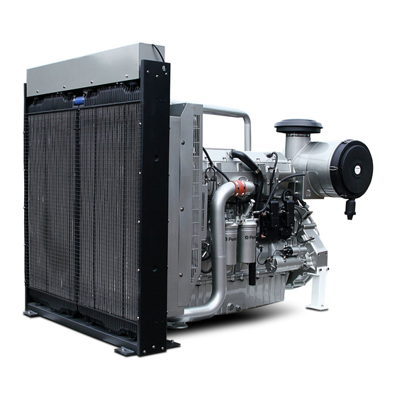
Page 3: Engine Views
2800 Series Engine views Introduction Perkins engines are built for specific applications and the views which follow do not necessarily match your engine specification. Location of engine parts Front and left side view of engine (A) 1 Radiator 6 Earth stud... - Page 4 2800 Series Rear and right side view of engine (B) 1 Radiator 7 Thermostat housing 2 Restriction indicator 8 Dipstick 3 Air cleaner 9 Sump drain plug 4 Turbochargers 10 Lubricating oil filter 5 Exhaust manifold 11 Flywheel housing 6 Filler cap for lubricating oil...
-
Page 5: How To Start The Engine
Note: A system fault may be indicated after the engine is started. If this occurs the ECM has detected a problem with the system. Investigate the cause, if necessary use the Perkins service tool EST. Caution: Oil pressure should rise within 15 seconds after the engine starts. The electronic engine controls monitor the oil pressure and will stop the engine if the oil pressure is below normal. -
Page 6: After The Engine Has Started
4 A system fault may be indicated after the engine is started. If this occurs the ECM has detected a problem with the system. Investigate the cause, if necessary use the Perkins service tool EST. Refer to the Diagnostic Manual for more information on engine diagnostics. -
Page 7: Engine Emergency Stop
2800 Series Engine emergency stop Caution: Emergency shut-off controls are for emergency use only. Do not use emergency shut-off devices or controls for the normal stop procedure. Ensure that any components for the external system that support the engine operation are secured after the engine is stopped. -
Page 8: Engine Diagnostics
ECM can be retrieved with Perkins electronic service tools. The codes that have been logged can be cleared with Perkins electronic service tools. The codes that have been logged in the memory of the ECM will be automatically cleared from the memory after 100 hours. If the engine is operated in protection override mode, then low engine oil pressure and high engine coolant temperature events cannot be cleared without a factory password. - Page 9 Electronic Control Module (ECM). Some parameters may affect engine operation. This may lead to complaints from the operator about power or performance. The engine related parameters which follow may be programmed by the customer, by use of the Perkins electronic service tool, to influence the operation of the engine:...
-
Page 10: Preventive Maintenance Periods
2800 Series Preventive maintenance Preventive maintenance periods These preventive maintenance periods apply to average conditions of operation. Check the periods given by the manufacturer of the equipment in which the engine is installed. Use the periods which are shortest. When the operation of the engine must conform to the local regulations these periods and procedures may need to be adapted to ensure correct operation of the engine. - Page 11 (2) If fuel with a high sulphur content is used, the lubricating oil may have to be replaced at more frequent intervals. Contact the Applications Department (Stafford) at Perkins Engines Company Limited. (3) This procedure must be done by a person who has had the correct training.
-
Page 12: How To Check The Coolant Level
2800 Series How to check the coolant level Check the coolant level when the engine is stopped and cool. Warning! On a hot engine release the filler cap carefully as the system will be under pressure. 1 Remove the filler cap from the expansion tank slowly to relieve the pressure. -
Page 13: How To Check The Lubricating Oil Level
2800 Series How to check the lubricating oil level Warning! Hot oil and hot components can cause personal injury. Do not allow hot oil or hot components to contact the skin. At the periods given in the service schedule use the dipstick to check the amount of lubricating oil in the sump. -
Page 14: Visual Inspection
2800 Series Visual inspection A visual inspection should take only a few minutes and can prevent costly repairs and accidents. For maximum engine life, inspect the engine compartment before the engine is started. Look for items such as oil or coolant leaks, loose fastenings, worn belts or loose connections. Repair as necessary. -
Page 15: Diagnostics Check
2800 Series Diagnostics check At the periods specified in the service schedule, use the Perkins Electronic Service Tool to retrieve the diagnostic codes. A key to the codes is given below. Refer to the relevant Diagnostic Manual for further details. - Page 16 2800 Series CID-FMI Diagnostic code description 324-03 Engine warning lamp open/short to B+ 324-04 Engine warning lamp short to ground 324-05 Engine warning lamp open circuit 342-02 Engine speed sensor No. 2 data intermittent 342-11, 12 Engine speed sensor No. 2 mechanical fault...
- Page 17 2800 Series How to renew the element of the primary fuel filter Cautions: Do not allow dirt to enter the fuel system. Clean thoroughly the area around a fuel system component that will be disconnected. Fit a suitable cover to any disconnected component of the fuel system.
- Page 18 Fit a new ‘O’ ring seal to the top of the housing. Cautions: It is important that only genuine Perkins parts are used. The use of non Perkins parts could damage the fuel injection equipment. Do not fill the primary fuel filter with fuel before installation. The fuel would not be filtered and could be contaminated.
- Page 19 2800 Series How to renew the element of the secondary fuel filter Cautions: Do not allow dirt to enter the fuel system. Clean thoroughly the area around a fuel system component that will be disconnected. Fit a suitable cover to any disconnected component of the fuel system.
- Page 20 Fit a new ‘O’ ring seal to the top of the housing. Cautions: It is important that only genuine parts are used. The use of non Perkins parts could damage the fuel injection equipment. Do not fill the secondary fuel filter with fuel before installation. The fuel would not be filtered and could be contaminated.
- Page 21 An oil sample kit (part number KRP1572), which includes the relevant sample bottles, is available from Perkins dealers. Certain engines are fitted with an oil sample valve (A1), use the relevant procedure given below.
- Page 22 2800 Series Engines without an oil sample valve 1 Run the engine until the normal temperature of operation is achieved, stop the engine and proceed with the operation immediately. 2 Use a vacuum pump and a long flexible tube: remove the engine oil dipstick, insert the flexible tube into the dipstick tube and withdraw the oil sample.
-
Page 23: How To Renew The Engine Lubricating Oil
2800 Series How to renew the engine lubricating oil Warnings! Hot oil and hot components can cause personal injury. Do not allow hot oil or hot components to contact the skin. Discard the used filter element and used engine oil in a safe place and in accordance with local regulations. - Page 24 2800 Series 4 Clean the area around the oil filler cap (B1) and remove the cap. Fill the sump to the “H” mark on the dipstick (B2) with clean new lubricating oil of the correct grade as given in "Lubricating oil specification" on page 52.
- Page 25 Caution: It is important that only genuine Perkins parts are used. The use of non Perkins parts could damage the engine. The correct filter element will be marked with the symbol shown (B).
- Page 26 2800 Series How to renew the air cleaner element The air filter contains a paper element. This must not be washed. Renew the paper element as follows: 1 Loosen the clamp and remove the end cover (A1). Withdraw and discard the filter element (A2).
- Page 27 2800 Series How to check the fan drive belts Check all drive belts and renew a belt if it is worn or damaged. Where more than one belt is used between two pulleys, all of the belts must be renewed together. Maximum belt life will be obtained only if the belts are kept at the correct tensions.
- Page 28 2800 Series How to adjust the tension of the alternator belt Remove the access panel in the fan guard and proceed as follows. Use a Borroughs belt tension gauge to check the tension at (A5). It should be 625 N (461 lbf ft) 63,73 kgf. To...
- Page 29 2800 Series How to renew the fan drive belts 1 Remove the fan guards. 2 Remove the six setscrews which secure the fan and hub assembly to the pulley and remove the assembly. Caution: Take care during the removal of the fan; ensure that the radiator does not become damaged.
-
Page 30: Earth Stud
2800 Series Earth stud Inspect the wiring harness for good connections and inspect the condition of the harness. Check the tightness of the earth stud (A1) at the periods specified in the service schedule. The earth stud is fitted below the ECM at the left side of the crankcase. - Page 31 2800 Series Hoses and hose clips Inspect all hoses for leaks which may be caused by: Cracks Softness Loose clips Renew hoses that are cracked or soft. Tighten any loose clips. Check for these conditions: End fittings that are damaged or leaking...
- Page 32 2800 Series How to clean the radiator Inspect the radiator for damaged fins, corrosion, dirt, grease, insects, leaves, oil, and other debris. Clean the exterior of the radiator, if necessary. Warnings! During the use of high pressure air, wear a protective face shield and protective clothing.
- Page 33 To avoid air locks, the coolant system must be filled at a rate not faster than 19 L (4.2 UK gal) per minute. If the recommended coolant and procedures are not used, Perkins Engines Company Limited cannot be held responsible for damage caused by frost or corrosion or for loss of cooling efficiency.
- Page 34 2800 Series How to check the tappet clearances Special tools Description Part number Engine turning tool CH11148 Tappet clearances Inlet 0,38 +/- 0,08 mm (0.015 +/- 0.003 in) Exhaust 0,76 +/- 0,08 mm (0.030 +/- 0.003 in) The tappet clearance is measured between the rocker levers and the top of the valve bridge pieces. The operation must be done with the engine cold and stopped.
- Page 35 2800 Series 5 Check the inlet and exhaust valves of the number 1 cylinder. If they are fully closed the piston is on its compression stroke and the rocker levers can be moved by hand. If the rocker levers can not be moved because the valves are slightly open, the piston is on its exhaust stroke.
- Page 36 2800 Series 10 Check the tappet clearances for the inlet valves (C1) on cylinders 3, 5 and 6. Adjust the clearances if necessary. Check the tappet clearances for the exhaust valves (C2) on cylinders 2, 4 and 6, and adjust the clearances if necessary.
- Page 37 2800 Series How to check/adjust the electronic unit injectors Special tools Description Part number Fuel injector setting gauge CH11149 This operation should be performed at the same time as the operation to check the valve tappet clearances. Warning! The electrical circuit for the fuel injector units operates on 110 volts. Do NOT work on the fuel injector units unless the power supply to the ECM has been disconnected.
-
Page 38: Engine Protection Devices
If any of the sensors fail, the diagnostics indicator will be activated and your Perkins dealer should be contacted so that the fault can be identified by use of the Perkins Electronic Service Tool (EST). - Page 39 2800 Series How to renew the thermostats of the coolant system Renew the coolant thermostats at the periods given in the service schedule. This is recommended preventive maintenance practice. Warnings! Do not remove the coolant filler cap while the engine is still hot and the system is under pressure because dangerous hot coolant can be discharged.
- Page 40 2800 Series 6 Remove the two short setscrews which remain, separate the two halves of the assembly and remove the thermostats. 7 Clean thoroughly both parts of the assembly and check the condition of the lip-type seals. Renew the seals if they are worn or damaged.
- Page 41 2800 Series How to clean and to calibrate the engine speed/timing sensors 1 Disconnect the wiring harness from the sensor and remove the two speed-timing sensors from the left side of the engine at the back of the gear case.
- Page 42 At the periods given in the service schedule, with the engine switched off and cool, disconnect and remove the pipes from between the air filter and the turbochargers. Turn, rapidly, the rotor assembly of each turbocharger, check for freedom of movement and for sounds of interference. If necessary, contact your Perkins dealer/distributor.
- Page 43 Inspect the coolant pump for leaks. If leakage is observed, renew the coolant pump seal or the coolant pump assembly. Refer to the Workshop Manual for the dismantle and assembly procedures. Refer to the Workshop Manual or consult your Perkins dealer/distributor if any repair or replacement is needed. Notes: A small amount of leakage of coolant across the surface of the face seal in the water pump is normal.
-
Page 44: How To Eliminate Air From The Fuel System
2800 Series How to eliminate air from the fuel system This procedure is used normally when the engine runs out of fuel. 1 Loosen the union of the fuel return pipe (A1). Unlock and operate the hand priming pump (A2) until fuel, free from air, flows from the union;... -
Page 45: Engine Fluids
General fuel requirements are: Maximum sulphur content 0.2%; minimum Cetane number 45. Fuel cleanliness The modern, high pressure fuel injection system used on the 2800 Series engine requires a high level of fuel cleanliness to ensure correct operation and reliability. -
Page 46: Lubricating Oil Specification
2800 Series Water quality Soft water means de-ionised water, distilled water, rain water or water from a mains supply which has the following requirements: Chlorides - 40 mg/l max, sulphates - 100 mg/l max, total hardness 170 mg/l max, total solids 340 mg/l max and pH of 5.5 to 9.0. -
Page 47: Fault Diagnosis
2800 Series Fault diagnosis Problems and possible causes Possible causes Problem Checks by the workshop Checks by the user personnel The starter motor turns the engine too slowly 1, 2, 3, 4 5, 6, 7, 8, 9, 10, 12, 13,... -
Page 48: List Of Possible Causes
30 Restriction in air or water passages of radiator. 31 Restriction in breather pipe. 32 Insufficient coolant in system. 33 Vacuum pipe leak or fault in exhauster (not applicable to 2800 series engines). 34 Fault in fuel injection pump. 35 Broken drive on fuel injection pump. - Page 49 2800 Series 44 Piston rings are not free or they are worn or broken. 45 Valve stems and/or guides are worn. 46 Crankshaft bearings are worn or damaged. 47 Lubricating oil pump is worn. 48 Relief valve does not close.
Need help?
Do you have a question about the 2800 series and is the answer not in the manual?
Questions and answers