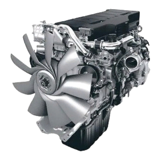
Summary of Contents for Perkins 2206-E13
-
Page 1: Troubleshooting
KENR6908-00 May 2008 Troubleshooting 2206-E13 Industrial Engine TGB (Engine) TGD (Engine) TGF (Engine) This document has been printed from SPI². Not for Resale... -
Page 2: Important Safety Information
These changes can affect the service that is given to the product. Obtain the complete and most current information before you start any job. Perkins dealers or Perkins distributors have the most current information available. When replacement parts are required for this product Perkins recommends using Perkins replacement parts. -
Page 3: Table Of Contents
KENR6908 Table of Contents Table of Contents CID 0005 FMI 11 ........... 55 CID 0006 FMI 11 ........... 56 CID 0041 FMI 03 ..........56 CID 0041 FMI 04 ..........56 Troubleshooting Section CID 0091 FMI 08 ..........57 CID 0100 FMI 03 ..........57 Electronic Troubleshooting CID 0100 FMI 04 .......... - Page 4 KENR6908 Table of Contents Calibration Procedures Engine Speed/Timing Sensor - Calibrate .... 138 Index Section Index ..............140 This document has been printed from SPI². Not for Resale...
-
Page 5: System Overview
KENR6908 Troubleshooting Section Troubleshooting Section Electronic Troubleshooting i02547521 System Overview System Operation g01277565 Illustration 1 Block diagram for the 2506-15 engine (1) 12 Pin Connector (7) 36 + 1 Tooth Gear (13) Inlet Manifold Pressure Sensor (2) Electronic Control Module (ECM) (8) Camshaft Position Sensor (14) Coolant Temperature Sensor (3) Electronic Unit Injectors... -
Page 6: Electronic Service Tools
Certain parameters that affect the engine operation voltage signal, the ECM can control injection timing may be changed with the Perkins Electronic and the ECM can control the amount of fuel that is Service Tool (EST). The parameters are stored injected. - Page 7 Code – Refer to “Diagnostic Code” or “Event Code”. DT, DT Connector, or Deutsch DT – This is a type Communication Adapter – The communication of connector that is used on Perkins engines. The adapter provides a communication link between the connectors are manufactured by Deutsch.
- Page 8 KENR6908 Troubleshooting Section Electronic Control Module (ECM) – The ECM 7 – The mechanical system is not responding is the control computer of the engine. The ECM properly. provides power to the electronics. The ECM monitors data that is input from the sensors of the engine. The 8 –...
-
Page 9: Factory Passwords
KENR6908 Troubleshooting Section Power Cycling – Power cycling happens when Hertz (Hz) – Hertz is the measure of electrical power to the ECM is cycled: ON, OFF, and ON. frequency in cycles per second. Power cycling refers to the action of cycling the Injector Codes –... -
Page 10: System Configuration Parameters
Perkins Electronic Service Tools are designed to help the service technician: • Diagnostic codes • Obtain data. • Engine configuration • Diagnose faults. The Perkins EST can be used by the technician to perform the following functions: This document has been printed from SPI². Not for Resale... - Page 11 • Set parameters Table 2 lists the service tools that are required in order to use Perkins EST. Table 2 Service Tools for the Use of Perkins EST Part Description Number Personal Computer (PC) Single user license for Perkins EST...
-
Page 12: Battery
KENR6908 Troubleshooting Section b. Print the parameters from the “Configuration” i02822887 screen on the electronic service tool. If a printer Replacing the ECM is unavailable, record all of the parameters. Make a note of any logged diagnostic codes and logged event codes for your records. NOTICE c. - Page 13 KENR6908 Troubleshooting Section d. If the “Copy Configuration” process from Step Logged codes may not indicate that a repair is 1.c was unsuccessful, manually program the needed. The fault may have been temporary. The ECM parameters. The parameters must match fault may have been resolved since the logging of the parameters from Step 1.b.
- Page 14 Thank you very much for your reading. Please Click Here. Then Get COMPLETE MANUAL. NO WAITING NOTE: If there is no response to click on the link above, please download the PDF document first and then click on it.
- Page 15 KENR6908 Troubleshooting Section i03034640 Sensors and Electrical Connectors Table 3 Connector Function J1/P1 ECM Connector (70-Pin Machine Harness) J2/P2 ECM Connector (120-Pin Engine Harness) Optional Customer Connector J61/P61 (40-Pin Connector) J63/P63 Diagnostic Connector (9-Pin Connector) J100/P100 Coolant Temperature Sensor (2-Pin Connector) J103/P103 Inlet Manifold Temperature Sensor...
- Page 16 KENR6908 Troubleshooting Section g01407090 Illustration 4 Block diagram for the 2206-13 engine components (1) 12-Pin Connector (7) 36 + 1 Tooth gear (13) Inlet manifold pressure sensor (2) Electronic Control Module (ECM) (8) Camshaft position sensor (14) Coolant temperature sensor (3) Electronic unit Injectors (9) Timing calibration probe (15) Engine oil pressure sensor...
- Page 17 KENR6908 Troubleshooting Section g01433340 Illustration 5 Locations of the sensors on the 2206-13 engine (17) Coolant temperature sensor (20) Fuel temperature sensor (23) Inlet manifold temperature sensor (18) Camshaft position sensor (21) Engine oil pressure sensor (24) Crankshaft position sensor (19) Atmospheric pressure sensor (22) Inlet manifold pressure sensor This document has been printed from SPI².
- Page 18 KENR6908 Troubleshooting Section g01278305 Illustration 6 Block diagram for the machine components This document has been printed from SPI². Not for Resale...
-
Page 19: Engine Wiring Information
Use the schematic with the latest revision number. Harness Wire Identification Perkins identifies all wires with eleven solid colors. The circuit number is stamped on the wire at a 25 mm (1 inch) spacing. Table 4 lists the wire colors and the color codes.


Need help?
Do you have a question about the 2206-E13 and is the answer not in the manual?
Questions and answers