Table of Contents
Advertisement
Quick Links
TPS23881EVM: PoE, PSE, TPS23881 Evaluation Module
This user's guide describes the evaluation modules (EVM) for the TPS23881 (TPS23881EVM-008 and
BOOST-PSEMTHR-007). The EVM contains evaluation and reference circuitry for the TPS23881. The
TPS23881 is a Power-over-Ethernet (PoE) device for power sourcing equipment (PSE).
....................................................................................................................
1
....................................................................................................................
2
3
4
5
6
7
1
2
3
4
5
6
7
8
9
10
11
12
13
14
15
16
17
18
19
20
21
22
23
1
2
....................................................................................................................
3
4
.......................................................................................................
......................................................................................
.................................................................................................
.............................................................................................................
.............................................................................................
....................................................................................
...................................................................................
..................................................................................
..................................................................................
...............................................................................................................
............................................................................................................
..................................................................................
.............................................................................................
.............................................................................................................
Copyright © 2019, Texas Instruments Incorporated
SLVUBP0A - May 2019 - Revised August 2019
Contents
..............................................
List of Figures
.......................................................................
.............................................................................
...........................................................................
.........................................................
...................................................
......................................................................
.........................................................
...........................................................
.............................................................
.............................................................
.......................................................
...........................................................
.............................................................
.........................................................
.......................................................
List of Tables
...................................................................
TPS23881EVM: PoE, PSE, TPS23881 Evaluation Module
User's Guide
2
2
6
8
8
17
28
4
5
9
10
10
11
12
13
14
16
17
18
19
20
21
22
23
24
25
26
26
26
27
3
6
6
7
1
Advertisement
Table of Contents

Subscribe to Our Youtube Channel
Related Manuals for Texas Instruments TPS23881EVM


Summary of Contents for Texas Instruments TPS23881EVM
-
Page 1: Table Of Contents
SLVUBP0A – May 2019 – Revised August 2019 TPS23881EVM: PoE, PSE, TPS23881 Evaluation Module This user’s guide describes the evaluation modules (EVM) for the TPS23881 (TPS23881EVM-008 and BOOST-PSEMTHR-007). The EVM contains evaluation and reference circuitry for the TPS23881. The TPS23881 is a Power-over-Ethernet (PoE) device for power sourcing equipment (PSE). -
Page 2: Description
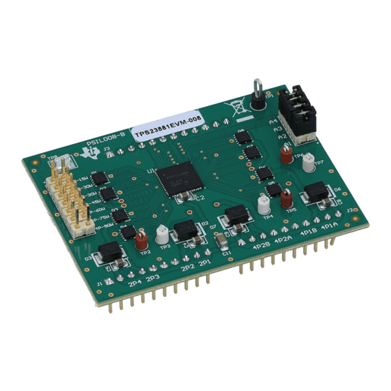
All other trademarks are the property of their respective owners. Description The TPS23881EVM features the 8-channel, TPS23881 and IEEE 802.3bt (draft) PoE PSE controller. The EVM consists of a motherboard (BOOST-PSEMTHR-007) and a daughterboard (TPS23881EVM-008) containing one TPS23881 device. The TPS23881EVM provides a multi-port base platform interface for... -
Page 3: Tps23881Evm Voltage Rail Current Requirements
LM5019 provides a basic power-on sequence and provides a well-controlled and consistent start-up. In addition to 54 V, the TPS23881 requires 3.3 V for the digital circuitry and this is routed up to TPS23881EVM-008 over the connector interface. The current consumption is 6-mA typical and 12-mA maximum. -
Page 4: Basic Setup Using Usb2Any
Operation with I C Monitoring) An I C interface is provided through J2 to the TPS23881 devices on the TPS23881EVM-008. The USB2ANY adapter (not included) can be used with any TI GUI which uses USB2ANY to read and write over an I C bus. -
Page 5: Advanced Setup Using Launchpad
If a jumper is installed on J5, DC power supply needs to be on before connecting MSP430 LaunchPad to PC and starting I2C communication. SLVUBP0A – May 2019 – Revised August 2019 TPS23881EVM: PoE, PSE, TPS23881 Evaluation Module Submit Documentation Feedback Copyright © 2019, Texas Instruments Incorporated... -
Page 6: General Use Features
C (mates with LaunchPad J2) LaunchPad power (onboard, mates with LaunchPad J6) TPS23881EVM-008 control (mates with TPS23881EVM-008 J3) TPS23881EVM-008 Channel 5–8 (mates with TPS23881EVM-008 J2) TPS23881EVM-008 Channel 1–4 (mates with TPS23881EVM-008 J1) Two-pair port 1 data only 2 Pair Port 1... -
Page 7: Evm Test Points
Open AUTO pin selection(autonomous mode is enabled if connecting auto pin to ground with selected resistance ) SLVUBP0A – May 2019 – Revised August 2019 TPS23881EVM: PoE, PSE, TPS23881 Evaluation Module Submit Documentation Feedback Copyright © 2019, Texas Instruments Incorporated... -
Page 8: Tps23881 Autonomous Operations
0xFFh TPS23881EVM GUI Setup TPS23881EVM GUI Installation TI's TPS23881EVM GUI is used with the TPS23881EVM to control the port and provide real-time feedback on port telemetry. Download the TPS23881EVM GUI from the TPS23881 product folder page the Tools and software section. -
Page 9: Tps23881Evm Gui Start-Up Window
TPS23881EVM GUI Setup www.ti.com Figure 3. TPS23881EVM GUI Start-up Window The default device address in the GUI is set to 0x20 which matches the default configuration of the EVM (J4 on the daughter card is installed with jumpers). The GUI sets the TPS23881 in configuration B mode (see the GENERAL MASK Register section of the data sheet for details). -
Page 10: Tps23881Evm Gui Load Firmware 1
TPS23881EVM GUI Setup www.ti.com Figure 4. TPS23881EVM GUI Load Firmware 1 Figure 5. TPS23881EVM GUI Load Firmware 2 TPS23881EVM: PoE, PSE, TPS23881 Evaluation Module SLVUBP0A – May 2019 – Revised August 2019 Submit Documentation Feedback Copyright © 2019, Texas Instruments Incorporated... -
Page 11: Device Configuration And Port Telemetry Page
Figure 6. Device Configuration and Port Telemetry Page The GUI also provides access to every register of the device in the register map. SLVUBP0A – May 2019 – Revised August 2019 TPS23881EVM: PoE, PSE, TPS23881 Evaluation Module Submit Documentation Feedback Copyright © 2019, Texas Instruments Incorporated... -
Page 12: Register Map
TPS23881EVM GUI Setup www.ti.com Figure 7. Register Map TPS23881EVM: PoE, PSE, TPS23881 Evaluation Module SLVUBP0A – May 2019 – Revised August 2019 Submit Documentation Feedback Copyright © 2019, Texas Instruments Incorporated... -
Page 13: Program Started
Basic CCS and Terminal Setup Use the following steps for basic CCS and terminal setup: 1. Launch the CCS program on the PC: Start → Texas Instruments → Code Composer Studio 7.2.0 → Code Composer Studio 7.2.0. 2. OK the workspace location and CCS starts. -
Page 14: Terminal Response With Connected Ports
TPS23881EVM GUI Setup www.ti.com 10. The TPS23881EVM is now waiting for a PD load to be installed. As ports are installed, the system automatically detects, classifies, and powers up the port as shown in Figure 9. Port status is updated on the screen approximately every 10 seconds. - Page 15 Multi-port power management The MSP430 communicates with the PC through UART, reporting the parameter and status of the port. SLVUBP0A – May 2019 – Revised August 2019 TPS23881EVM: PoE, PSE, TPS23881 Evaluation Module Submit Documentation Feedback Copyright © 2019, Texas Instruments Incorporated...
-
Page 16: Auto Mode System Software Structure
RJ45 port Power off all ports (QDEOH DOO SRUWV¶ GHWHFWLRQ& classification Figure 10. Auto Mode System Software Structure TPS23881EVM: PoE, PSE, TPS23881 Evaluation Module SLVUBP0A – May 2019 – Revised August 2019 Submit Documentation Feedback Copyright © 2019, Texas Instruments Incorporated... -
Page 17: Evm Schematic, Layout Guidelines, Pcb Assembly And Layer Plots
Power On Port/ classification Figure 11. Semi Auto Mode System Software Structure EVM Schematic, Layout Guidelines, PCB Assembly and Layer Plots This section contains the TPS23881EVM schematic, layout guidelines, printed-circuit board (PCB) assembly and layer plots. Schematic Figure 12 through Figure 14 illustrate the TPS23881EVM (daughter card+motherboard) schematics. -
Page 18: Boost-Psemthr-007 (Motherboard) Schematic: Control
EVM Schematic, Layout Guidelines, PCB Assembly and Layer Plots www.ti.com Figure 12. BOOST-PSEMTHR-007 (Motherboard) Schematic: Control TPS23881EVM: PoE, PSE, TPS23881 Evaluation Module SLVUBP0A – May 2019 – Revised August 2019 Submit Documentation Feedback Copyright © 2019, Texas Instruments Incorporated... -
Page 19: Boost-Psemthr-007 (Motherboard) Schematic: Power Ports
2 Pair Port 1 2 Pair Port 2 2200pF 2000V EARTH 7693 Figure 13. BOOST-PSEMTHR-007 (Motherboard) Schematic: Power Ports SLVUBP0A – May 2019 – Revised August 2019 TPS23881EVM: PoE, PSE, TPS23881 Evaluation Module Submit Documentation Feedback Copyright © 2019, Texas Instruments Incorporated... -
Page 20: Tps23881Evm-008 (Daughterboard) Schematic
2 Pair Ports 1-4 VPWR PSE_N5 PSE_N6 PSE_N1 PSE_N2 PSE_N7 PSE_N8 PSE_N3 PSE_N4 5011 Figure 14. TPS23881EVM-008 (Daughterboard) Schematic TPS23881EVM: PoE, PSE, TPS23881 Evaluation Module SLVUBP0A – May 2019 – Revised August 2019 Submit Documentation Feedback Copyright © 2019, Texas Instruments Incorporated... -
Page 21: Boost-Psemthr-007 (Motherboard) Top Side Assembly
Figure 23 show the PCB layouts and assemblies for this EVM. Figure 15. BOOST-PSEMTHR-007 (Motherboard) Top Side Assembly SLVUBP0A – May 2019 – Revised August 2019 TPS23881EVM: PoE, PSE, TPS23881 Evaluation Module Submit Documentation Feedback Copyright © 2019, Texas Instruments Incorporated... -
Page 22: Boost-Psemthr-007 (Motherboard) Top Side Routing
EVM Schematic, Layout Guidelines, PCB Assembly and Layer Plots www.ti.com Figure 16. BOOST-PSEMTHR-007 (Motherboard) Top Side Routing TPS23881EVM: PoE, PSE, TPS23881 Evaluation Module SLVUBP0A – May 2019 – Revised August 2019 Submit Documentation Feedback Copyright © 2019, Texas Instruments Incorporated... -
Page 23: Boost-Psemthr-007 (Motherboard) Layer 2 Routing
EVM Schematic, Layout Guidelines, PCB Assembly and Layer Plots www.ti.com Figure 17. BOOST-PSEMTHR-007 (Motherboard) Layer 2 Routing SLVUBP0A – May 2019 – Revised August 2019 TPS23881EVM: PoE, PSE, TPS23881 Evaluation Module Submit Documentation Feedback Copyright © 2019, Texas Instruments Incorporated... -
Page 24: Boost-Psemthr-007 (Motherboard) Layer 3 Routing
EVM Schematic, Layout Guidelines, PCB Assembly and Layer Plots www.ti.com Figure 18. BOOST-PSEMTHR-007 (Motherboard) Layer 3 Routing TPS23881EVM: PoE, PSE, TPS23881 Evaluation Module SLVUBP0A – May 2019 – Revised August 2019 Submit Documentation Feedback Copyright © 2019, Texas Instruments Incorporated... -
Page 25: Boost-Psemthr-007 (Motherboard) Bottom Side Routing
EVM Schematic, Layout Guidelines, PCB Assembly and Layer Plots www.ti.com Figure 19. BOOST-PSEMTHR-007 (Motherboard) Bottom Side Routing SLVUBP0A – May 2019 – Revised August 2019 TPS23881EVM: PoE, PSE, TPS23881 Evaluation Module Submit Documentation Feedback Copyright © 2019, Texas Instruments Incorporated... -
Page 26: Tps23881Evm-008 (Daughterboard) Top Side Assembly
EVM Schematic, Layout Guidelines, PCB Assembly and Layer Plots www.ti.com Figure 20. TPS23881EVM-008 (Daughterboard) Top Side Assembly Figure 21. TPS23881EVM-008 (Daughterboard) Top Side Routing Figure 22. TPS23881EVM-008 (Daughterboard) Bottom Side Routing TPS23881EVM: PoE, PSE, TPS23881 Evaluation Module SLVUBP0A – May 2019 – Revised August 2019 Submit Documentation Feedback Copyright ©... -
Page 27: Tps23881Evm-008 (Daughterboard) Bottom Side Assembly
EVM Schematic, Layout Guidelines, PCB Assembly and Layer Plots www.ti.com Figure 23. TPS23881EVM-008 (Daughterboard) Bottom Side Assembly NOTE: TPS23881EVM-008 Rev B does not have a 10 nF capacitor on AUTO. It will be added to Rev C. SLVUBP0A – May 2019 – Revised August 2019... -
Page 28: Bill Of Materials
Bill of Materials www.ti.com Bill of Materials The BOMs for the BOOST-PSEMTHR-007 and TPS23881EVM-008 are listed in Table 7 Table 8, respectively. Table 7. BOOST-PSEMTHR-007 Bill of Materials ALTERNATE DESIGNATOR VALUE DESCRIPTION PACKAGE REFERENCE PART NUMBER MANFACTURER ALTERNATE PART NUMBER... - Page 29 CAP, CERM, 1 µF, 10 V, ±10%, X7R, 0805 0805 0805ZC105KAT2A 0.1 µF CAP, CERM, 0.1 µF, 50 V, ±10%, X7R, 0603 0603 06035C104KAT2A SLVUBP0A – May 2019 – Revised August 2019 TPS23881EVM: PoE, PSE, TPS23881 Evaluation Module Submit Documentation Feedback Copyright © 2019, Texas Instruments Incorporated...
- Page 30 Bill of Materials www.ti.com Table 8. TPS23881EVM-008 Bill of Material ALTERNATE PART ALTERNATE DESIGNATOR VALUE DESCRIPTION PACKAGE REFERENCE PART NUMBER MANUFACTURER NUMBER MANUFACTURER !PCB Printed Circuit Board PSIL008 CAP, CERM, 0.1 µF, 0.1 µF 50 V, +/- 10%, X7R, 0603...
- Page 31 Bill of Materials www.ti.com Table 8. TPS23881EVM-008 Bill of Material (continued) ALTERNATE PART ALTERNATE DESIGNATOR VALUE DESCRIPTION PACKAGE REFERENCE PART NUMBER MANUFACTURER NUMBER MANUFACTURER RES, 15.8 k, 1%, 15.8 k 0.125 W, AEC-Q200 0805 ERJ-6ENF1582V Panasonic Grade 0, 0805 RES, 11.0 k, 1%, 11.0 k...
-
Page 32: Slvubp0A - May 2019 - Revised August 2019
........................ • Made edits in Section 5.2 .......... • Deleted the TPS23881EVM GUI Quick Start Window image. Changed this image 5 Revision History SLVUBP0A – May 2019 – Revised August 2019 Submit Documentation Feedback Copyright © 2019, Texas Instruments Incorporated... - Page 33 STANDARD TERMS FOR EVALUATION MODULES Delivery: TI delivers TI evaluation boards, kits, or modules, including any accompanying demonstration software, components, and/or documentation which may be provided together or separately (collectively, an “EVM” or “EVMs”) to the User (“User”) in accordance with the terms set forth herein.
- Page 34 www.ti.com Regulatory Notices: 3.1 United States 3.1.1 Notice applicable to EVMs not FCC-Approved: FCC NOTICE: This kit is designed to allow product developers to evaluate electronic components, circuitry, or software associated with the kit to determine whether to incorporate such items in a finished product and software developers to write software applications for use with the end product.
- Page 35 www.ti.com Concernant les EVMs avec antennes détachables Conformément à la réglementation d'Industrie Canada, le présent émetteur radio peut fonctionner avec une antenne d'un type et d'un gain maximal (ou inférieur) approuvé pour l'émetteur par Industrie Canada. Dans le but de réduire les risques de brouillage radioélectrique à...
- Page 36 www.ti.com EVM Use Restrictions and Warnings: 4.1 EVMS ARE NOT FOR USE IN FUNCTIONAL SAFETY AND/OR SAFETY CRITICAL EVALUATIONS, INCLUDING BUT NOT LIMITED TO EVALUATIONS OF LIFE SUPPORT APPLICATIONS. 4.2 User must read and apply the user guide and other available documentation provided by TI regarding the EVM prior to handling or using the EVM, including without limitation any warning or restriction notices.
- Page 37 Notwithstanding the foregoing, any judgment may be enforced in any United States or foreign court, and TI may seek injunctive relief in any United States or foreign court. Mailing Address: Texas Instruments, Post Office Box 655303, Dallas, Texas 75265 Copyright © 2019, Texas Instruments Incorporated...
- Page 38 TI products. TI’s provision of these resources does not expand or otherwise alter TI’s applicable warranties or warranty disclaimers for TI products. Mailing Address: Texas Instruments, Post Office Box 655303, Dallas, Texas 75265 Copyright © 2019, Texas Instruments Incorporated...
Need help?
Do you have a question about the TPS23881EVM and is the answer not in the manual?
Questions and answers