Advertisement
Quick Links
www.ti.com
EVM User's Guide: TPS25730EVM
TPS25730 Evaluation Module
Description
The TPS25730D is a stand-alone USB Type-C
and Power Delivery (PD) controller providing cable
plug and orientation detection at the USB Type-C
connector. Upon cable plug and orientation detection,
the TPS25730D device communicates on the CC line
using the USB-PD protocol. Upon connection, the
TPS25730D enables the power path. When cable
detection and USB-PD negotiation are complete, the
negotiated voltage is passed through the power path.
Additionally, the EVM has the I2C interface accessible
by a header for debugging, as well as various test
points for signal probing.
SLVUCP4 – NOVEMBER 2023
Submit Document Feedback
Get Started
®
1. Order the EVM on
2. Download the data sheet (SLVSGP9)
3. Download the technical reference manual
(SLVUCJ7)
4. Obtain a USB PD source such as
Features
•
Sink only
•
Resistor configurable
•
No firmware development or external memory
required
•
Minimum and maximum voltage configurable
•
Operating and maximum current configurable
•
Capabilities mismatch
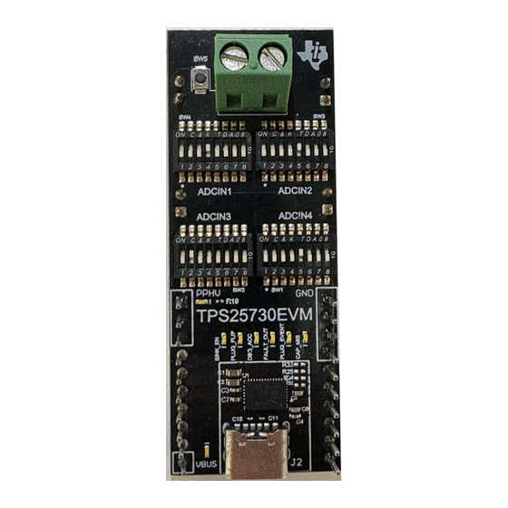
TPS25730EVM Top View
Copyright © 2023 Texas Instruments Incorporated
Description
ti.com
TPS25750EVM
TPS25730 Evaluation Module
1
Advertisement

Related Manuals for Texas Instruments TPS25730


Summary of Contents for Texas Instruments TPS25730
- Page 1 • Minimum and maximum voltage configurable • Operating and maximum current configurable • Capabilities mismatch TPS25730EVM Top View SLVUCP4 – NOVEMBER 2023 TPS25730 Evaluation Module Submit Document Feedback Copyright © 2023 Texas Instruments Incorporated...
-
Page 2: Kit Contents
1 TPS25730EVM 1.3 Specification This section describes applications for the TPS25730. The TPS25730 is a PD controller that enables the sinking of power to the system through a USB-C connector using the USB-PD specification, as shown in Figure 1-1. Due to the ability to configure power settings by voltage dividers at the ADCINx pins, no EEPROM is needed, which reduces BOM cost and saves board space. -
Page 3: Device Information
1.4 Device Information The TPS25730EVM allows for the configuration of the TPS25730 without the need to program or use software. As the TPS25730 is a USB-PD controller for use in sink-only applications, the following sink capabilities of the TPS25730EVM are configurable: •... -
Page 4: Header Information
The TPS25730EVM has one terminal block to allow for connection of a load at J1. This enables testing of the TPS25730 under load. The positive wire of the load needs to be connected to the hole closest to the TI logo, and the ground wire of the load needs to be connected to the hole closest to the SW5 switch. -
Page 5: Push Buttons
LDO_3V3 2.4 Push Buttons Push button SW5 controls the FAULT_IN GPIO input. Pressing the SW5 button sets FAULT_IN to logical high. The use of FAULT_IN is detailed in the TPS25730 data sheet (SLVSGP9). 2.5 Debug Information 2.6 Test Points The test points available are as follows: Table 2-3. - Page 6 2.7 Configuring the TPS25730EVM The TPS25730EVM provides device status information of the TPS25730 using LEDs that correspond to GPIO events of the TPS25730. Each LED has the corresponding event printed to the left when the TPS25730EVM is oriented with TPS25730EVM readable.
- Page 7 Capabilities Mismatch bit is set on the USB PD request. Table 2-8. Maximum Voltage Configuration for Sink Capabilities - ADCIN2 Decoded ADCIN2 Decoded Value Maximum Voltage Configuration 12 V 15 V 20 V SLVUCP4 – NOVEMBER 2023 TPS25730 Evaluation Module Submit Document Feedback Copyright © 2023 Texas Instruments Incorporated...
- Page 8 1.5 A 1.5 A 1.5 A 1.5 A 1.5 A 1.5 A 2.5 A 2.5 A 2.5 A 3.5 A 3.5 A 4.5 A TPS25730 Evaluation Module SLVUCP4 – NOVEMBER 2023 Submit Document Feedback Copyright © 2023 Texas Instruments Incorporated...
- Page 9 5 V to 20 V (including 5 V and 20 V) cannot be provided. The plug flip LED lights up if the plug is inserted upside down. SLVUCP4 – NOVEMBER 2023 TPS25730 Evaluation Module Submit Document Feedback Copyright © 2023 Texas Instruments Incorporated...
- Page 10 LDO_3V3 LDO_3V3 FAULT_IN U_LEDDriver LEDDriver.SchDoc GPIO DBG_ACC LDO_3V3 LDO_3V3 U_LEDDriver LEDDriver.SchDoc PLUG_FLIP GPIO LDO_3V3 LDO_3V3 11.0k 11.0k U_LEDDriver LEDDriver.SchDoc SINK_EN GPIO LDO_3V3 LDO_3V3 SINK_EN TPS25730 Evaluation Module SLVUCP4 – NOVEMBER 2023 Submit Document Feedback Copyright © 2023 Texas Instruments Incorporated...
- Page 11 100k 100k PSIL212_Hardware.SchDoc ADCIN1 ADCIN2 ADCIN3 ADCIN4 Reserved_26 Reserved_27 10uF 10uF 0.1uF 100k 100k 100k 100k Place close to chip LDO_3V3 11.0k 33.0k GPIO SLVUCP4 – NOVEMBER 2023 TPS25730 Evaluation Module Submit Document Feedback Copyright © 2023 Texas Instruments Incorporated...
- Page 12 Change R39, R41, R49, R51, R59, R61, R69, R71 to 10k ohm Change R38, R40, R42, R43, R48, R50, R52, R53, R58, R60, R62, R63, R68, R70, R72, R73 to 20k ohm TPS25730 Evaluation Module SLVUCP4 – NOVEMBER 2023 Submit Document Feedback Copyright © 2023 Texas Instruments Incorporated...
- Page 13 Hardware Design Files 3.2 PCB Layouts Figure 3-1 through Figure 3-6 illustrate the EVM PCB layouts. Figure 3-1. TPS25730EVM Top Composite View SLVUCP4 – NOVEMBER 2023 TPS25730 Evaluation Module Submit Document Feedback Copyright © 2023 Texas Instruments Incorporated...
- Page 14 Hardware Design Files www.ti.com Figure 3-2. TPS25730EVM Top Layer TPS25730 Evaluation Module SLVUCP4 – NOVEMBER 2023 Submit Document Feedback Copyright © 2023 Texas Instruments Incorporated...
- Page 15 Hardware Design Files Figure 3-3. TPS25730EVM Ground Plane SLVUCP4 – NOVEMBER 2023 TPS25730 Evaluation Module Submit Document Feedback Copyright © 2023 Texas Instruments Incorporated...
- Page 16 Hardware Design Files www.ti.com Figure 3-4. TPS25730EVM Power Layer TPS25730 Evaluation Module SLVUCP4 – NOVEMBER 2023 Submit Document Feedback Copyright © 2023 Texas Instruments Incorporated...
- Page 17 Hardware Design Files Figure 3-5. TPS25730 Bottom Layer SLVUCP4 – NOVEMBER 2023 TPS25730 Evaluation Module Submit Document Feedback Copyright © 2023 Texas Instruments Incorporated...
- Page 18 Hardware Design Files www.ti.com Figure 3-6. TPS25730 Bottom Composite View TPS25730 Evaluation Module SLVUCP4 – NOVEMBER 2023 Submit Document Feedback Copyright © 2023 Texas Instruments Incorporated...
- Page 19 2.2k RES, 2.20 k, 1%, 0.05 W, 0201 0201 CRCW02012K20FKED Vishay-Dale R36, R37 RES, 10 k, 5%, 0.05 W, 0201 0201 RC0201JS-7D10KL Yageo America SLVUCP4 – NOVEMBER 2023 TPS25730 Evaluation Module Submit Document Feedback Copyright © 2023 Texas Instruments Incorporated...
- Page 20 TPS25730DRJKR Texas Instruments with Integrated Power Switches Optimized for Power Applications 22 V 22-V Precision Surge Protection DRV0006A TVS2200DRVR Texas Instruments Clamp, DRV0006A (WSON-6) TPS25730 Evaluation Module SLVUCP4 – NOVEMBER 2023 Submit Document Feedback Copyright © 2023 Texas Instruments Incorporated...
-
Page 21: Additional Information
4.1 Trademarks USB Type-C ® and USB-C ® are registered trademarks of USB Implementers Forum. All trademarks are the property of their respective owners. SLVUCP4 – NOVEMBER 2023 TPS25730 Evaluation Module Submit Document Feedback Copyright © 2023 Texas Instruments Incorporated... - Page 22 STANDARD TERMS FOR EVALUATION MODULES Delivery: TI delivers TI evaluation boards, kits, or modules, including any accompanying demonstration software, components, and/or documentation which may be provided together or separately (collectively, an “EVM” or “EVMs”) to the User (“User”) in accordance with the terms set forth herein.
- Page 23 www.ti.com Regulatory Notices: 3.1 United States 3.1.1 Notice applicable to EVMs not FCC-Approved: FCC NOTICE: This kit is designed to allow product developers to evaluate electronic components, circuitry, or software associated with the kit to determine whether to incorporate such items in a finished product and software developers to write software applications for use with the end product.
- Page 24 www.ti.com Concernant les EVMs avec antennes détachables Conformément à la réglementation d'Industrie Canada, le présent émetteur radio peut fonctionner avec une antenne d'un type et d'un gain maximal (ou inférieur) approuvé pour l'émetteur par Industrie Canada. Dans le but de réduire les risques de brouillage radioélectrique à...
- Page 25 www.ti.com EVM Use Restrictions and Warnings: 4.1 EVMS ARE NOT FOR USE IN FUNCTIONAL SAFETY AND/OR SAFETY CRITICAL EVALUATIONS, INCLUDING BUT NOT LIMITED TO EVALUATIONS OF LIFE SUPPORT APPLICATIONS. 4.2 User must read and apply the user guide and other available documentation provided by TI regarding the EVM prior to handling or using the EVM, including without limitation any warning or restriction notices.
- Page 26 Notwithstanding the foregoing, any judgment may be enforced in any United States or foreign court, and TI may seek injunctive relief in any United States or foreign court. Mailing Address: Texas Instruments, Post Office Box 655303, Dallas, Texas 75265 Copyright © 2023, Texas Instruments Incorporated...
- Page 27 TI products. TI’s provision of these resources does not expand or otherwise alter TI’s applicable warranties or warranty disclaimers for TI products. TI objects to and rejects any additional or different terms you may have proposed. IMPORTANT NOTICE Mailing Address: Texas Instruments, Post Office Box 655303, Dallas, Texas 75265 Copyright © 2023, Texas Instruments Incorporated...
Need help?
Do you have a question about the TPS25730 and is the answer not in the manual?
Questions and answers