Table of Contents
Advertisement
Quick Links
www.ti.com
User's Guide
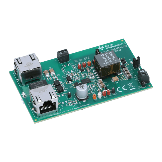
TPS23758EVM-080 Evaluation Module
This user's guide describes the TPS23758 evaluation module (EVM). The TPS23758 evaluation module
(TPS23758EVM-080) contains evaluation and reference circuitry for the TPS23758 device. The TPS23758
device is an IEEE 802.3at Type 1 compliant, powered-device (PD) controller and power supply controller
optimized for primary side regulation flyback converter topologies. The TPS23758EVM-080 is targeted for a 5-V
synchronous-rectified high efficiency 13-W PD solution.
1
Introduction.............................................................................................................................................................................2
2 Electrical Specifications........................................................................................................................................................
3 Description..............................................................................................................................................................................
4
Schematic................................................................................................................................................................................4
6 TPS23758EVM-080 Performance Data..................................................................................................................................
7 EVM Assembly Drawings and Layout Guidelines.............................................................................................................
8 Bill of Materials.....................................................................................................................................................................
9 Revision History...................................................................................................................................................................
Figure 6-1. Startup Response When Connected to a PoE PSE (TPS23880).............................................................................
Figure 6-2. DCDC Startup...........................................................................................................................................................
Figure 6-4. Efficiency of the TPS23758EVM-080........................................................................................................................
Figure 6-5. TPS23758EVM-080 Load Regulation.......................................................................................................................
Figure 6-6. DCDC Recovery from Output Short..........................................................................................................................
Figure 6-7. SRF = 0
Ω................................................................................................................................................................10
Ω............................................................................................................................................................10
Figure 6-9. SRR = 0 Ω...............................................................................................................................................................
Figure 6-10. SRR = 10 Ω...........................................................................................................................................................
Figure 7-2. Layer 2 Routing.......................................................................................................................................................
Figure 7-3. Layer 3 Routing.......................................................................................................................................................
Figure 7-4. Bottom-Side Routing...............................................................................................................................................
Table 5-1. Connector Functionality..............................................................................................................................................
Table 5-2. Test Points..................................................................................................................................................................
Trademarks
All trademarks are the property of their respective owners.
SLVUBO2B - APRIL 2019 - REVISED DECEMBER 2020
Submit Document Feedback
ABSTRACT
Table of Contents
Description................................................................................................................................5
List of Figures
Schematic.................................................................................................................................4
Placement.............................................................................................................................12
List of Tables
BOM.........................................................................................................................................16
Copyright © 2020 Texas Instruments Incorporated
Input.........................................................................................7
25°C....................................................................2
TPS23758EVM-080 Evaluation Module
Table of Contents
2
3
6
12
16
21
6
6
8
9
9
11
11
12
13
13
5
5
1
Advertisement
Table of Contents

Related Manuals for Texas Instruments TPS23758EVM-080


Summary of Contents for Texas Instruments TPS23758EVM-080
-
Page 1: Table Of Contents
(TPS23758EVM-080) contains evaluation and reference circuitry for the TPS23758 device. The TPS23758 device is an IEEE 802.3at Type 1 compliant, powered-device (PD) controller and power supply controller optimized for primary side regulation flyback converter topologies. The TPS23758EVM-080 is targeted for a 5-V synchronous-rectified high efficiency 13-W PD solution. -
Page 2: Introduction
Introduction www.ti.com 1 Introduction The TPS23758EVM-080 allows reference circuitry evaluation of the TPS23758 device. It contains input and output power connectors and an array of onboard test points for circuit evaluation. 1.1 Features • IEEE802.3at Type 1 compliant PoE PD •... -
Page 3: Description
Description 3 Description The TPS23758EVM-080 enables full evaluation of the TPS23758 device. Refer to the schematic shown in Figure 4-1. Ethernet power is applied from J1 and is dropped to the bridge rectifier (D1, D2). The Power over Ethernet (PoE) transformer needed to transfer power or data is T1. The Bob Smith Terminations help balance the Ethernet cable impedance and are critical for ESD and EMI or EMC performance. -
Page 4: Schematic
Schematic www.ti.com 4 Schematic Figure 4-1. TPS23758EVM-080 Schematic TPS23758EVM-080 Evaluation Module SLVUBO2B – APRIL 2019 – REVISED DECEMBER 2020 Submit Document Feedback Copyright © 2020 Texas Instruments Incorporated... -
Page 5: General Configuration And Description
DC-DC converter input RSNS Current sense voltage TP11 Soft start and hiccup timer TP12 PoE input return ground TP13 Feedback loop SLVUBO2B – APRIL 2019 – REVISED DECEMBER 2020 TPS23758EVM-080 Evaluation Module Submit Document Feedback Copyright © 2020 Texas Instruments Incorporated... -
Page 6: Tps23758Evm-080 Performance Data
6 TPS23758EVM-080 Performance Data 6.1 Startup to PSE and DCDC Startup Figure 6-1 shows the startup response of the TPS23758EVM-080. Figure 6-1. Startup Response When Connected to a PoE PSE (TPS23880) Figure 6-2. DCDC Startup TPS23758EVM-080 Evaluation Module SLVUBO2B – APRIL 2019 – REVISED DECEMBER 2020 Submit Document Feedback Copyright ©... -
Page 7: Figure 6-3. Transient Response From 100 Ma To 1 A For A 48-V
TPS23758EVM-080 Performance Data 6.2 Transient Response Figure 6-3 shows the transient response of the TPS23758EVM-080. Figure 6-3. Transient Response from 100 mA to 1 A for a 48-V Input SLVUBO2B – APRIL 2019 – REVISED DECEMBER 2020 TPS23758EVM-080 Evaluation Module Submit Document Feedback Copyright ©... -
Page 8: Figure 6-4. Efficiency Of The Tps23758Evm-080
TPS23758EVM-080 Performance Data www.ti.com 6.3 Efficiency Figure 6-4 shows the efficiency of the TPS23758EVM-080. Figure 6-4. Efficiency of the TPS23758EVM-080 TPS23758EVM-080 Evaluation Module SLVUBO2B – APRIL 2019 – REVISED DECEMBER 2020 Submit Document Feedback Copyright © 2020 Texas Instruments Incorporated... -
Page 9: Figure 6-5. Tps23758Evm-080 Load Regulation
TPS23758EVM-080 Performance Data 6.4 Load Regulation Figure 6-5. TPS23758EVM-080 Load Regulation 6.5 Recovery from VOUT Short Figure 6-6. DCDC Recovery from Output Short SLVUBO2B – APRIL 2019 – REVISED DECEMBER 2020 TPS23758EVM-080 Evaluation Module Submit Document Feedback Copyright © 2020 Texas Instruments Incorporated... -
Page 10: Figure 6-7. Srf
TPS23758EVM-080 Performance Data www.ti.com 6.6 Slew Rate Adjust Figure 6-7. SRF = 0 Ω Figure 6-8. SRF = 100 Ω TPS23758EVM-080 Evaluation Module SLVUBO2B – APRIL 2019 – REVISED DECEMBER 2020 Submit Document Feedback Copyright © 2020 Texas Instruments Incorporated... -
Page 11: Figure 6-9. Srr = 0 Ω
TPS23758EVM-080 Performance Data Figure 6-9. SRR = 0 Ω Figure 6-10. SRR = 10 Ω SLVUBO2B – APRIL 2019 – REVISED DECEMBER 2020 TPS23758EVM-080 Evaluation Module Submit Document Feedback Copyright © 2020 Texas Instruments Incorporated... -
Page 12: Evm Assembly Drawings And Layout Guidelines
7 EVM Assembly Drawings and Layout Guidelines 7.1 PCB Drawings Figure 7-1 Figure 7-4 show the component placement and layout of the TPS23758EVM-080. Figure 7-1. Top-Side Component Placement Figure 7-2. Layer 2 Routing TPS23758EVM-080 Evaluation Module SLVUBO2B – APRIL 2019 – REVISED DECEMBER 2020 Submit Document Feedback Copyright ©... -
Page 13: Figure 7-3. Layer 3 Routing
EVM Assembly Drawings and Layout Guidelines Figure 7-3. Layer 3 Routing Figure 7-4. Bottom-Side Routing SLVUBO2B – APRIL 2019 – REVISED DECEMBER 2020 TPS23758EVM-080 Evaluation Module Submit Document Feedback Copyright © 2020 Texas Instruments Incorporated... - Page 14 Keep the high-current and high-voltage switching away from low-level sensing circuits including those outside the power supply. • Proper spacing around the high-voltage sections of the converter. TPS23758EVM-080 Evaluation Module SLVUBO2B – APRIL 2019 – REVISED DECEMBER 2020 Submit Document Feedback Copyright © 2020 Texas Instruments Incorporated...
- Page 15 • Possible use of integrated RJ-45 jacks (shielded with internal transformer and Bob Smith terminations). • End-product enclosure considerations (shielding). SLVUBO2B – APRIL 2019 – REVISED DECEMBER 2020 TPS23758EVM-080 Evaluation Module Submit Document Feedback Copyright © 2020 Texas Instruments Incorporated...
-
Page 16: Bill Of Materials
50 V, +/- 10%, X7R, 0603 0.22 uF CAP, CERM, 0.22 1206 C3216X7R2A224 uF, 100 V, +/- 10%, K115AA X7R, 1206 TPS23758EVM-080 Evaluation Module SLVUBO2B – APRIL 2019 – REVISED DECEMBER 2020 Submit Document Feedback Copyright © 2020 Texas Instruments Incorporated... - Page 17 Bill of Materials Table 8-1. TPS23758EVM-080 BOM (continued) Designator Quantity Value Description PackageReference PartNumber Manufacturer Alternate Alternate PartNumber Manufacturer 1 uF CAP, CERM, 1 uF, 0603 GCM188R71E10 MuRata 25 V, +/- 10%, X7R, 5KA64D AEC-Q200 Grade 1, 0603 22 pF...
- Page 18 Bill of Materials www.ti.com Table 8-1. TPS23758EVM-080 BOM (continued) Designator Quantity Value Description PackageReference PartNumber Manufacturer Alternate Alternate PartNumber Manufacturer H1, H2, H3, H4 Bumpon, Transparent Bumpon SJ-5303 Hemisphere, 0.44 X (CLEAR) 0.20, Clear J1, J2 RJ45, No LED, tab 16.26 x 14.54 x 15.75 1-406541-1...
- Page 19 Bill of Materials Table 8-1. TPS23758EVM-080 BOM (continued) Designator Quantity Value Description PackageReference PartNumber Manufacturer Alternate Alternate PartNumber Manufacturer RES, 1.0 K, 5%, 0402 CRCW04020000 Vishay-Dale 0.063 W, AEC- Z0ED Q200 Grade 0, 0402 49.9 RES, 49.9, 1%, 0402...
- Page 20 Bill of Materials www.ti.com Table 8-1. TPS23758EVM-080 BOM (continued) Designator Quantity Value Description PackageReference PartNumber Manufacturer Alternate Alternate PartNumber Manufacturer 350 uH Transformer, 350 358 x 236 x 500 mil H2019FNLT Pulse Engineering uH, SMT 150 uH Transformer, 150 14 x 16.2 mm...
-
Page 21: Revision History
Updated the numbering format for tables, figures and cross-references throughout the document....2 • Updated Schematic............................• Updated Bill of Materials...........................16 SLVUBO2B – APRIL 2019 – REVISED DECEMBER 2020 TPS23758EVM-080 Evaluation Module Submit Document Feedback Copyright © 2020 Texas Instruments Incorporated... - Page 22 STANDARD TERMS FOR EVALUATION MODULES Delivery: TI delivers TI evaluation boards, kits, or modules, including any accompanying demonstration software, components, and/or documentation which may be provided together or separately (collectively, an “EVM” or “EVMs”) to the User (“User”) in accordance with the terms set forth herein.
- Page 23 www.ti.com Regulatory Notices: 3.1 United States 3.1.1 Notice applicable to EVMs not FCC-Approved: FCC NOTICE: This kit is designed to allow product developers to evaluate electronic components, circuitry, or software associated with the kit to determine whether to incorporate such items in a finished product and software developers to write software applications for use with the end product.
- Page 24 www.ti.com Concernant les EVMs avec antennes détachables Conformément à la réglementation d'Industrie Canada, le présent émetteur radio peut fonctionner avec une antenne d'un type et d'un gain maximal (ou inférieur) approuvé pour l'émetteur par Industrie Canada. Dans le but de réduire les risques de brouillage radioélectrique à...
- Page 25 www.ti.com EVM Use Restrictions and Warnings: 4.1 EVMS ARE NOT FOR USE IN FUNCTIONAL SAFETY AND/OR SAFETY CRITICAL EVALUATIONS, INCLUDING BUT NOT LIMITED TO EVALUATIONS OF LIFE SUPPORT APPLICATIONS. 4.2 User must read and apply the user guide and other available documentation provided by TI regarding the EVM prior to handling or using the EVM, including without limitation any warning or restriction notices.
- Page 26 Notwithstanding the foregoing, any judgment may be enforced in any United States or foreign court, and TI may seek injunctive relief in any United States or foreign court. Mailing Address: Texas Instruments, Post Office Box 655303, Dallas, Texas 75265 Copyright © 2019, Texas Instruments Incorporated...
- Page 27 TI products. TI’s provision of these resources does not expand or otherwise alter TI’s applicable warranties or warranty disclaimers for TI products. Mailing Address: Texas Instruments, Post Office Box 655303, Dallas, Texas 75265 Copyright © 2020, Texas Instruments Incorporated...
Need help?
Do you have a question about the TPS23758EVM-080 and is the answer not in the manual?
Questions and answers