Advertisement
Quick Links
www.ti.com
EVM User's Guide: TPS23881B1EVM
PoE, PSE, TPS23881B1 Evaluation Module
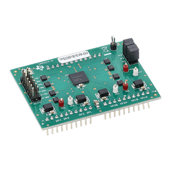
Description
The TPS23881B1EVM features the 8-channel,
TPS23881B1 and IEEE 802.3bt compliant PoE PSE
controller. The EVM consists of a motherboard
(BOOST-PSEMTHR-007) and a daughterboard
(TPS23881B1EVM-024) containing one TPS23881B1
device. The TPS23881B1EVM provides a multi-port
base platform interface for TPS23881B1EVM-024,
MSP-EXP430FR5969
(LaunchPad
(USB Interface Adapter).
Get Started
1. Order the TPS23881B1EVM-024,
PSEMTHR-007, and
2. Read the TPS23881B1EVM-024 user's guide
3. Start development with the TPS2388x EVM GUI
4. Refer to the data sheet or
support
SLVUCV7 – APRIL 2024
Submit Document Feedback
™
), and
USB2ANY
BOOST-
USB2ANY
E2E
for questions and
Copyright © 2024 Texas Instruments Incorporated
Features
•
Four IEEE802.3bt 2-pair ports with 1000BASE-T
(gigabit Ethernet
™
data pass-through)
•
Two IEEE802.3bt 4-pair ports with 1000BASE-T
(gigabit Ethernet data pass-through)
•
Single DC power supply input
•
Onboard 3.3V regulator
2
•
Onboard I
C interface to both TPS23881B1
devices from either
USB2ANY
EXP430FR5969
•
Port ON status LEDs
•
User test points
Applications
•
Enterprise and SoHO
•
Connected ceiling
LED switches
•
PoE pass-through power modules
•
Network video recorders (NVRs)
•
Wireless backhaul and small-cell networking
PoE, PSE, TPS23881B1 Evaluation Module
Description
or
MSP-
switches and routers
1
Advertisement

Related Manuals for Texas Instruments TPS23881B1


Summary of Contents for Texas Instruments TPS23881B1
- Page 1 PoE, PSE, TPS23881B1 Evaluation Module Description Features The TPS23881B1EVM features the 8-channel, • Four IEEE802.3bt 2-pair ports with 1000BASE-T TPS23881B1 and IEEE 802.3bt compliant PoE PSE (gigabit Ethernet ™ data pass-through) controller. The EVM consists of a motherboard • Two IEEE802.3bt 4-pair ports with 1000BASE-T...
-
Page 2: Kit Contents
1 Evaluation Module Overview 1.1 Introduction This user’s guide describes the evaluation modules (EVM) for the TPS23881B1 (TPS23881B1EVM-024 and BOOST-PSEMTHR-007). The EVM contains evaluation and reference circuitry for the TPS23881B1. The TPS23881B1 is a Power-over-Ethernet (PoE) device for power sourcing equipment (PSE). - Page 3 Two-pair port 4 power is ON. For J7 supplier #1 (see the BOM), J7 internal port LED is active. For supplier #2, D12 is active. SLVUCV7 – APRIL 2024 PoE, PSE, TPS23881B1 Evaluation Module Submit Document Feedback Copyright © 2024 Texas Instruments Incorporated...
- Page 4 3.3V Used for TPS23881B1 VDD VPWR ground C Data from LaunchPad and USB-TO-GPIO C Clock from LaunchPad and USB-TO-GPIO PSE_SDAO C data out from TPS23881B1 PSE_SCL C clock to TPS23881B1 PSE_SDAI C data in to TPS23881B1 GND1 Ground from LaunchPad and USB2ANY...
-
Page 5: Quick Start
Reverse voltage protection is not provided; make sure that the correct polarity is applied to J1. This DC input is labeled VPWR in the schematics and is used for port VBUS as well as for the TPS23881B1 devices. The VPWR connections to the PoE ports are not fused. Each two-pair port is capable of furnishing at least 30 W and each four-pair port can furnish 90 W. - Page 6 2.5.4 Basic Test Setup Using Autonomous Mode The TPS23881B1 supports autonomous mode, which means The TPS23881B1 can operate without any host control. During power up the resistance on the AUTO pin is measured and the device is preconfigured according to the jumper configuration on J5 of the daughter board.
- Page 7 If a jumper is installed on J5, DC power supply needs to be on before turning on TPS2388xEVM GUI and starting I2C communication. 2.5.6 Advanced Test Setup Using MSP-EX430FR5969 LaunchPad The LaunchPad (not included) running a custom software program can communicate with the TPS23881B1 devices on the TPS23881B1EVM-024. Figure 2-2 shows the advanced setup using LaunchPad.
-
Page 8: Development Section
Software Development section. Follow the onscreen instructions to complete the installation. The TPS23881B1 GUI uses the USB2ANY as an interface between the PC USB port and the BOOST-PSEMTHR-007 J2 connector (I2C interface). Before starting the TPS23881B1 GUI, make sure the USB2ANY is properly connected to TPS23881B1EVM and the EVM is... - Page 9 The default device address in the GUI is set to 0x20 which matches the default configuration of the EVM (J4 on the daughter card is installed with jumpers). The GUI sets the TPS23881B1 in configuration B mode (see the GENERAL MASK Register section of the data sheet for details). The address can be programed through the A1 to A4 pins and the I2C address setting in the GUI needs to match the hardware configuration.
- Page 10 3-4, each port can be configured separately by clicking each RJ45 connector. By default, the TPS23881B1 is configured in OFF Mode. Each port can be configured by clicking the RJ45 icon. Clicking the SET ALL PORTS TO STANDARD button sets all port to standard configurations (configuring ports in Semi-Auto mode, enabling OSS, power policing, and DC disconnect).
- Page 11 3.1.3.1 Basic CCS and Terminal Setup Use the following steps for basic CCS and terminal setup: 1. Launch the CCS program on the PC: Start → Texas Instruments → Code Composer Studio 7.2.0 → Code Composer Studio 7.2.0. 2. OK the workspace location and CCS starts.
- Page 12 Figure 3-7. Port status is updated on the screen approximately every 10 seconds. Figure 3-7. Terminal Response With Connected Ports PoE, PSE, TPS23881B1 Evaluation Module SLVUCV7 – APRIL 2024 Submit Document Feedback Copyright © 2024 Texas Instruments Incorporated...
- Page 13 Auto mode operation is demonstrated in the MSP430 reference code and Figure 3-8 shows the flow chart. Basically, after configuration, the TPS23881B1 handles port detection, classification, turn on, and faults and there is no control needed from the host. Every 10...
- Page 14 Set Ports to SEMI_AUTO mode telemetry via UART (QDEOH 3RUWV¶ GHWHFWLRQ& Power On Port/ classification Figure 3-9. Semi Auto Mode System Software Structure PoE, PSE, TPS23881B1 Evaluation Module SLVUCV7 – APRIL 2024 Submit Document Feedback Copyright © 2024 Texas Instruments Incorporated...
- Page 15 4 Hardware Design Files 4.1 Schematic Figure 4-1 through Figure 4-3 illustrate the TPS23881B1EVM (daughter card+motherboard) schematics. Figure 4-1. BOOST-PSEMTHR-007 (Motherboard) Schematic: Control SLVUCV7 – APRIL 2024 PoE, PSE, TPS23881B1 Evaluation Module Submit Document Feedback Copyright © 2024 Texas Instruments Incorporated...
- Page 16 Shield GND Shield GND 2 Pair Port 1 2 Pair Port 2 2200pF 2000V EARTH 7693 Figure 4-2. BOOST-PSEMTHR-007 (Motherboard) Schematic: Power Ports PoE, PSE, TPS23881B1 Evaluation Module SLVUCV7 – APRIL 2024 Submit Document Feedback Copyright © 2024 Texas Instruments Incorporated...
- Page 17 P S E_N2 P S E_N7 P S E_N8 P S E_N3 P S E_N4 TP 1 5011 Figure 4-3. TPS23881B1EVM-024 (Daughterboard) Schematic SLVUCV7 – APRIL 2024 PoE, PSE, TPS23881B1 Evaluation Module Submit Document Feedback Copyright © 2024 Texas Instruments Incorporated...
- Page 18 PCB layouts and assemblies for this EVM. Figure 4-4. BOOST-PSEMTHR-007 (Motherboard) Top Side Assembly Figure 4-5. BOOST-PSEMTHR-007 (Motherboard) Top Side Routing PoE, PSE, TPS23881B1 Evaluation Module SLVUCV7 – APRIL 2024 Submit Document Feedback Copyright © 2024 Texas Instruments Incorporated...
- Page 19 Hardware Design Files Figure 4-6. BOOST-PSEMTHR-007 (Motherboard) Layer 2 Routing Figure 4-7. BOOST-PSEMTHR-007 (Motherboard) Layer 3 Routing SLVUCV7 – APRIL 2024 PoE, PSE, TPS23881B1 Evaluation Module Submit Document Feedback Copyright © 2024 Texas Instruments Incorporated...
- Page 20 Figure 4-8. BOOST-PSEMTHR-007 (Motherboard) Bottom Side Routing Figure 4-9. TPS23881B1EVM-024 (Daughterboard) Top Side Assembly Figure 4-10. TPS23881B1EVM-024 (Daughterboard) Top Side Routing PoE, PSE, TPS23881B1 Evaluation Module SLVUCV7 – APRIL 2024 Submit Document Feedback Copyright © 2024 Texas Instruments Incorporated...
-
Page 21: Layout Guidelines
TPS23881B1EVM-024 Rev B does not have a 10nF capacitor on AUTO. This will be added to Rev C. 4.2.1 Layout Guidelines 4.2.1.1 Supply Voltage Decoupling Provide power supply pin bypass to the TPS23881B1 device as follows: • 0.1µF, 100V, X7R ceramic at pin 28 (VPWR) •... - Page 22 Wurth Elektronik Brass, TH Terminal Block Technology Header (shrouded), 100 mil, 5x2, 5x2 Shrouded N2510-6002-RB 61201021621 Wurth Elektronik High-Temperature, Gold, TH header PoE, PSE, TPS23881B1 Evaluation Module SLVUCV7 – APRIL 2024 Submit Document Feedback Copyright © 2024 Texas Instruments Incorporated...
- Page 23 Shunt, 100 mil, Flash Gold, Black SPC02SYAN SH-J5, SH-J6, Shunt Solutions SH-J7, SH-J8 TP1, TP2 Test Point, Multipurpose, Red, TH Keystone5010 5010 Keystone SLVUCV7 – APRIL 2024 PoE, PSE, TPS23881B1 Evaluation Module Submit Document Feedback Copyright © 2024 Texas Instruments Incorporated...
- Page 24 06035C104KAT2A X7R, 0603 Unless otherwise noted in the Alternate Part Number or Alternate Manufacturer columns, all parts can be substituted with equivalents. PoE, PSE, TPS23881B1 Evaluation Module SLVUCV7 – APRIL 2024 Submit Document Feedback Copyright © 2024 Texas Instruments Incorporated...
- Page 25 Q200 Grade 0, 0805 SH-J1, SH-J2, Closed Top 100mil Sullins Connector Shunt, 100 mil, Flash Gold, Black SPC02SYAN SH-J3, SH-J4 Shunt Solutions SLVUCV7 – APRIL 2024 PoE, PSE, TPS23881B1 Evaluation Module Submit Document Feedback Copyright © 2024 Texas Instruments Incorporated...
- Page 26 0805 CRM0805-FX-R510ELF Bourns Unless otherwise noted in the Alternate Part Number or Alternate Manufacturer columns, all parts can be substituted with equivalents. PoE, PSE, TPS23881B1 Evaluation Module SLVUCV7 – APRIL 2024 Submit Document Feedback Copyright © 2024 Texas Instruments Incorporated...
-
Page 27: Additional Information
Texas Instruments. ™ Ethernet is a trademark of ODVA, Inc. All trademarks are the property of their respective owners. SLVUCV7 – APRIL 2024 PoE, PSE, TPS23881B1 Evaluation Module Submit Document Feedback Copyright © 2024 Texas Instruments Incorporated... - Page 28 STANDARD TERMS FOR EVALUATION MODULES Delivery: TI delivers TI evaluation boards, kits, or modules, including any accompanying demonstration software, components, and/or documentation which may be provided together or separately (collectively, an “EVM” or “EVMs”) to the User (“User”) in accordance with the terms set forth herein.
- Page 29 www.ti.com Regulatory Notices: 3.1 United States 3.1.1 Notice applicable to EVMs not FCC-Approved: FCC NOTICE: This kit is designed to allow product developers to evaluate electronic components, circuitry, or software associated with the kit to determine whether to incorporate such items in a finished product and software developers to write software applications for use with the end product.
- Page 30 www.ti.com Concernant les EVMs avec antennes détachables Conformément à la réglementation d'Industrie Canada, le présent émetteur radio peut fonctionner avec une antenne d'un type et d'un gain maximal (ou inférieur) approuvé pour l'émetteur par Industrie Canada. Dans le but de réduire les risques de brouillage radioélectrique à...
- Page 31 www.ti.com EVM Use Restrictions and Warnings: 4.1 EVMS ARE NOT FOR USE IN FUNCTIONAL SAFETY AND/OR SAFETY CRITICAL EVALUATIONS, INCLUDING BUT NOT LIMITED TO EVALUATIONS OF LIFE SUPPORT APPLICATIONS. 4.2 User must read and apply the user guide and other available documentation provided by TI regarding the EVM prior to handling or using the EVM, including without limitation any warning or restriction notices.
- Page 32 Notwithstanding the foregoing, any judgment may be enforced in any United States or foreign court, and TI may seek injunctive relief in any United States or foreign court. Mailing Address: Texas Instruments, Post Office Box 655303, Dallas, Texas 75265 Copyright © 2023, Texas Instruments Incorporated...
- Page 33 TI products. TI’s provision of these resources does not expand or otherwise alter TI’s applicable warranties or warranty disclaimers for TI products. TI objects to and rejects any additional or different terms you may have proposed. IMPORTANT NOTICE Mailing Address: Texas Instruments, Post Office Box 655303, Dallas, Texas 75265 Copyright © 2024, Texas Instruments Incorporated...
Need help?
Do you have a question about the TPS23881B1 and is the answer not in the manual?
Questions and answers