Table of Contents
Advertisement
Quick Links
TPS2358 Dual-Slot ATCA™ AdvancedMC™ Controller
1
Introduction
The Dual-Slot AdvancedMC™ Controller Evaluation Module (EVM) is a PCB platform for users to learn
about the features and operation of the TPS2358 integrated circuit from Texas Instruments (TI). The
TPS2358 Dual-Slot ATCA™ AdvancedMC™ Controller manages two 12-V and two 3.3-V power rails, and
features inrush and fault current limiting, FET OR'ing, input UVLO protection and logic-level enable inputs.
Current control on the 12-V rails has a high degree of programmability, including independent current limit
and fast trip thresholds. Overcurrent fault timing is managed with user-programmable shut-down delays,
and each of the four power channels has dedicated fault and power good reporting outputs. In addition,
current sense and pass and block FET's for the 3.3-V channels are fully integrated into the device.
Power management applications based on the TPS2358 are easily configured to meet the requirements
for 12-V and 3.3-V control of Advanced Mezzanine Card (AdvancedMC™) modules. Each device
incorporated onto a Carrier Card provides full control for two AdvancedMC™ slots according to the
requirements of the Advanced Telecommunications Computing Architecture (ATCA™) specification,
PICMG 3.0. In addition, the input supply FET OR'ing control for the 12-V rails facilitates efficient redundant
supply implementations in Micro Telecommunications Computing Architecture (MicroTCA™) systems.
2
Description
2.1
Module Overview
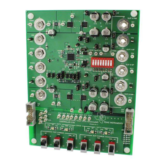
The TPS2358EVM is a single-board evaluation platform consisting of two main sections. When oriented
with the board nomenclature and switch labels in a normal, upright reading position towards the user, the
top portion contains the TPS2358 device and typically required components. The bottom section contains
more ancillary circuitry intended to facilitate exercising the device through various application scenarios.
Power connectors are organized with inputs along the left edge of the board, outputs along the right.
The main (upper) section of the board is comprised of the four power channels, including the featured
device, support passives, input and output banana jacks, control FET's (for 12-V rails), and power planes.
The board contains various capacitors for simulation of input bulk capacitance as may be present on
driven AdvancedMC™ modules; alternatively, the user's test loads can be connected at the output banana
jacks. Various timing capacitor options, for each power rail, are available and user-selectable via DIP
switch S7. Numerous jumpers are provided throughout the circuit for maximum configuration flexibility.
Test points are available for voltage and waveform monitoring.
The bottom section contains two expansion port connectors and the status LED's. Slide switches for
actuation of the chip enable inputs are organized in a row along the bottom edge of the PCB.
All trademarks are the property of their respective owners.
SLUU328 – August 2008
Submit Documentation Feedback
TPS2358 Dual-Slot ATCA™ AdvancedMC™ Controller Evaluation Module
User's Guide
SLUU328 – August 2008
Evaluation Module
1
Advertisement
Table of Contents

Subscribe to Our Youtube Channel
Related Manuals for Texas Instruments Dual-Slot ATCA AdvancedMC TPS2358


Summary of Contents for Texas Instruments Dual-Slot ATCA AdvancedMC TPS2358
- Page 1 The Dual-Slot AdvancedMC™ Controller Evaluation Module (EVM) is a PCB platform for users to learn about the features and operation of the TPS2358 integrated circuit from Texas Instruments (TI). The TPS2358 Dual-Slot ATCA™ AdvancedMC™ Controller manages two 12-V and two 3.3-V power rails, and features inrush and fault current limiting, FET OR’ing, input UVLO protection and logic-level enable inputs.
-
Page 2: Typical Applications
Description www.ti.com Typical Applications The TPS2358EVM was designed with independent input and output banana jacks for up to two each 12-V input and 3.3-V input power supplies, and up to two each 12-V and 3.3-V output power rails. This provides the greatest flexibility for configuring the EVM for either ATCA™... -
Page 3: Electrical Specifications
Electrical Specifications www.ti.com Electrical Specifications Absolute Maximum Ratings The absolute maximum ratings for the TPS2358EVM are given below in Table (1) (2) Table 1. Absolute Maximum Ratings PARAMETER RATING Input voltage range, +12-V supply –0.3 V to 13.8 V Input voltage range, +3.3-V supply –0.3 V to 4 V Applied voltage, pins of J21, J22 EN12x, ORENx –0.3 V to (V... -
Page 4: Electrical Characteristics
Electrical Specifications www.ti.com Electrical Characteristics The electrical characteristics of the TPS2358EVM are as listed in Table Table 3. Electrical Characteristics, TPS2358EVM PARAMETER CONDITIONS TYP MAX UNITS UNLESS OTHERWISE NOTED: V (12VINx) and V (3V3INx) per Table 2 under (for specified V ). -
Page 5: Schematic Diagram
Schematic Diagram www.ti.com Schematic Diagram The schematic diagram for the TPS2358EVM is shown in Figure 1 Figure Figure 1. TPS2358 Evaluation Module Schematic Diagram, Sheet 1 SLUU328 – August 2008 TPS2358 Dual-Slot ATCA™ AdvancedMC™ Controller Evaluation Module Submit Documentation Feedback... - Page 6 Schematic Diagram www.ti.com Figure 2. TPS2358 Evaluation Module Schematic Diagram, Sheet 2 TPS2358 Dual-Slot ATCA™ AdvancedMC™ Controller Evaluation Module SLUU328 – August 2008 Submit Documentation Feedback...
-
Page 7: Equipment Requirements
Test Set-Up www.ti.com Test Set-Up Equipment Requirements The following test and interface equipment (not supplied) is required to verify EVM module operation, and begin using the EVM. • Power supply, 3.3 VDC, 500 mA minimum • Power supply, 15 VDC, 10 A minimum •... -
Page 8: Test Procedure
Test Procedure www.ti.com Test Procedure The following procedure can be used to verify functional operation of the EVM assembly upon receipt. Jumper Installation The TPS2358EVM makes use of various jumpers for quick change of functional configurations. Verify the module was supplied with shunt jumpers installed across the headers listed in Table 5. - Page 9 Test Procedure www.ti.com Check-Out Steps Turn the voltage adjust knobs of both power supplies fully CCW. Adjust the current limit control of the 15-V supply for 10 amps minimum output. If not already done, connect the EVM and test equipment as shown in Figure Turn on the 3.3-V power supply, and adjust the output for 3.3 V 5% at test point TP2.
- Page 10 Test Procedure www.ti.com Move the Channel 3 scope probe to test point TP30. Set the scope to trigger on Channel 2. Place the EVM SLOT B MP ENABLE switch in the LO position. The SLOT B MP green STATUS LED should illuminate.
- Page 11 Test Procedure www.ti.com Remove the current probe from the 3.3 V supply lead, and clamp it across the 12VIN2 supply lead. Change the Channel 4 amplifier setting to 5 A/div. Set the time base to 500 S/div, and adjust the scope trigger threshold to about 3 volts.
- Page 12 Test Procedure www.ti.com Reconnect the Channel 3 scope probe to test point TP33. Set the scope to trigger on Channel 1. Disconnect the current probe and reconnect it across the 12VIN1 supply lead. Move the probe ground lead to test point TP9. Set the SLOT A PWR ENABLE switch to the LO position. The SLOT A PWR green STATUS LED should illuminate.
-
Page 13: Test Points
EVM Feature Details www.ti.com EVM Feature Details Test Points The TPS2358EVM contains numerous test points throughout the circuit for user monitoring of waveforms and voltage measurement. Table 7 lists the module test points and the signal available at each one. The EVM PCB layout connects all ground nodes and supply returns to a common GND node, via several power plane areas. - Page 14 EVM Feature Details www.ti.com Connecting Loads to the TPS2358EVM Each of the four power rails of the TPS2358EVM is supplied with some amount of load capacitance in the form of discrete electrolytics. The capacitors can be connected to or disconnected from their associated output nodes using 100-mil, 2-pin shunt jumpers across the on-board PCB headers.
- Page 15 Assembly Drawing and PCB Layout www.ti.com Assembly Drawing and PCB Layout The top assembly drawing and individual PCB layers for the TPS2358EVM are shown in the following figures. Figure 8. SLUU328 – August 2008 TPS2358 Dual-Slot ATCA™ AdvancedMC™ Controller Evaluation Module Submit Documentation Feedback...
- Page 16 Assembly Drawing and PCB Layout www.ti.com Figure 9. TPS2358 Dual-Slot ATCA™ AdvancedMC™ Controller Evaluation Module SLUU328 – August 2008 Submit Documentation Feedback...
- Page 17 Assembly Drawing and PCB Layout www.ti.com Figure 10. SLUU328 – August 2008 TPS2358 Dual-Slot ATCA™ AdvancedMC™ Controller Evaluation Module Submit Documentation Feedback...
- Page 18 Assembly Drawing and PCB Layout www.ti.com Figure 11. TPS2358 Dual-Slot ATCA™ AdvancedMC™ Controller Evaluation Module SLUU328 – August 2008 Submit Documentation Feedback...
- Page 19 Assembly Drawing and PCB Layout www.ti.com Figure 12. SLUU328 – August 2008 TPS2358 Dual-Slot ATCA™ AdvancedMC™ Controller Evaluation Module Submit Documentation Feedback...
- Page 20 Assembly Drawing and PCB Layout www.ti.com Figure 13. TPS2358 Dual-Slot ATCA™ AdvancedMC™ Controller Evaluation Module SLUU328 – August 2008 Submit Documentation Feedback...
-
Page 21: List Of Materials
List of Materials www.ti.com List of Materials Table 9. List of Materials COUNT REF DES DESCRIPTION PART NUMBER Capacitor, ceramic, 25 V, X7R, 20%, 0.1 µF, C1, C2, C3, C4, C5 Std. Std. 0805 Capacitor, aluminum, SM, 25 V, 20%, 47 µF, C10, C11 EEV-FK1E470P Panasonic... - Page 22 List of Materials www.ti.com Table 9. List of Materials (continued) COUNT REF DES DESCRIPTION PART NUMBER Resistor, chip, 1/10 W, 5%, 270 Ω, 0805 R12, R13 Std. Std. Resistor, chip, 1/10 W, 5%, 470 Ω, 0805 R17, R18, R19, R20, Std.
-
Page 23: Important Notice
IMPORTANT NOTICE Texas Instruments Incorporated and its subsidiaries (TI) reserve the right to make corrections, modifications, enhancements, improvements, and other changes to its products and services at any time and to discontinue any product or service without notice. Customers should obtain the latest relevant information before placing orders and should verify that such information is current and complete.
Need help?
Do you have a question about the Dual-Slot ATCA AdvancedMC TPS2358 and is the answer not in the manual?
Questions and answers