Table of Contents
Advertisement
Quick Links
www.ti.com
User's Guide
TPS23882B1EVM: PoE, PSE, TPS23882B1
Evaluation Module
This user's guide describes the evaluation modules (EVM) for the TPS23882B1 (TPS23882B1EVM-008 and
BOOST-PSEMTHR8-097). The EVM contains evaluation and reference circuitry for the TPS23882B1. The
TPS23882B1 is a Power-over-Ethernet (PoE) device for power sourcing equipment (PSE).
1 Description..............................................................................................................................................................................
1.1 Features.............................................................................................................................................................................
1.2
Applications........................................................................................................................................................................2
Start...............................................................................................................................................................................3
2.1 Input Power........................................................................................................................................................................
2.2 PoE Port Interfaces............................................................................................................................................................
2
C Interfaces.....................................................................................................................................................................
2.4 Basic Test Setup Using Autonomous Mode.......................................................................................................................
Features.............................................................................................................................................................7
LEDs..........................................................................................................................................................................7
Points.................................................................................................................................................................8
3.4 EVM Test Jumpers.............................................................................................................................................................
Setup........................................................................................................................................................10
4.1 TPS23882B1 GUI Installation..........................................................................................................................................
Operation.............................................................................................................................................10
4.3 MSP-EXP430FR5969 Details..........................................................................................................................................
4.4 MSP430 Reference Code................................................................................................................................................
5 EVM Schematic, Layout Guidelines, PCB Assembly and Layer Plots............................................................................
5.1 Schematic........................................................................................................................................................................
5.2 Layout Guidelines............................................................................................................................................................
Drawings..................................................................................................................................................................21
6 Bill of Materials.....................................................................................................................................................................
Trademarks
™
LaunchPad
and Code Composer Studio
All trademarks are the property of their respective owners.
SLVUC36 - APRIL 2021
Submit Document Feedback
ABSTRACT
Table of Contents
2
™
Switches.....................................................................................................................7
™
are trademarks of Texas Instruments.
Copyright © 2021 Texas Instruments Incorporated
.......................................................................................6
TPS23882B1EVM: PoE, PSE, TPS23882B1
Table of Contents
2
2
3
3
3
4
2
C Monitoring).....
5
9
10
14
16
17
18
21
26
1
Evaluation Module
Advertisement
Table of Contents

Related Manuals for Texas Instruments TPS23882B1EVM


Summary of Contents for Texas Instruments TPS23882B1EVM
-
Page 1: Table Of Contents
TPS23882B1EVM: PoE, PSE, TPS23882B1 Evaluation Module ABSTRACT This user’s guide describes the evaluation modules (EVM) for the TPS23882B1 (TPS23882B1EVM-008 and BOOST-PSEMTHR8-097). The EVM contains evaluation and reference circuitry for the TPS23882B1. The TPS23882B1 is a Power-over-Ethernet (PoE) device for power sourcing equipment (PSE). -
Page 2: Description
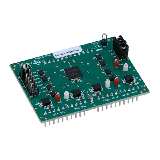
1 Description The TPS23882B1 features the TPS23882B1: an 8-channel, IEEE802.3bt compliant PoE PSE controller. The EVM consists of a motherboard (BOOST-PSEMTHR8-097) and a daughterboard (TPS23882B1EVM-008) containing one TPS23882B1 device. The TPS23882B1 EVM provides a multi-port base platform interface for ™... -
Page 3: Quick Start
In addition to 54 V, the TPS23882B1 requires 3.3 V for the digital circuitry and this is routed up to TPS23882B1EVM-008 over the connector interface. The current consumption is 6-mA typical and 12-mA maximum. -
Page 4: Basic Test Setup Using Autonomous Mode
2-pair ports are interoperable with PDs. Only 2P-15W and 2P-30W are valid selections on the TPS23882B1EVM-008 as the other resistors are not populated. To test with autonomous mode, install a jumper on the pins of J5 corresponding to the desired power level and... -
Page 5: Basic Test Setup Using Usb2Any For I
An I C interface is provided through J2 of the motherboard to the TPS23882B1 device on the TPS23882B1EVM-008. The USB2ANY adapter (not included) can be used with any TI GUI which uses USB2ANY to read and write over an I C bus. -
Page 6: Advanced Test Setup Using Msp-Ex430Fr5969 Launchpad
Do not press the RESET button (S1) on the motherboard while communicating over I2C. Pressing this button will set all ports to off mode and the reference code will not be able to recover. TPS23882B1EVM: PoE, PSE, TPS23882B1 SLVUC36 – APRIL 2021 Evaluation Module Submit Document Feedback Copyright © 2021 Texas Instruments Incorporated... -
Page 7: General Use Features
C (mates with LaunchPad J2) LaunchPad power (onboard, mates with LaunchPad J6) TPS23882B1EVM-008 control (mates with TPS23882B1EVM-008 J3) TPS23882B1EVM-008 Channel 5–8 (mates with TPS23882B1EVM-008 J2) TPS23882B1EVM-008 Channel 1–4 (mates with TPS23882B1EVM-008 J1) Two-pair port 1 data only 2 Pair Port 1... -
Page 8: Evm Test Points
Two-pair port 5 GATE 2P5D Two-pair port 5 DRAIN 2P6G Two-pair port 6 GATE 2P6D Two-pair port 6 DRAIN VPWR ground VPWR ground TPS23882B1EVM: PoE, PSE, TPS23882B1 SLVUC36 – APRIL 2021 Evaluation Module Submit Document Feedback Copyright © 2021 Texas Instruments Incorporated... -
Page 9: Evm Test Jumpers
AUTO pin selection (autonomous mode is enabled if connecting auto pin to ground with selected resistance, 2-pair 30-W operation is selected by default) SLVUC36 – APRIL 2021 TPS23882B1EVM: PoE, PSE, TPS23882B1 Submit Document Feedback Evaluation Module Copyright © 2021 Texas Instruments Incorporated... -
Page 10: Tps23882B1 Gui Setup
PSE switch. Links to the recommended PD device for each end equipment are also provided. Once the TPS23882B1 device is connected, click Firmware to select firmware to be loaded to TPS23882B1. TPS23882B1EVM: PoE, PSE, TPS23882B1 SLVUC36 – APRIL 2021 Evaluation Module Submit Document Feedback Copyright © 2021 Texas Instruments Incorporated... - Page 11 4-4, each port can be configured separately by clicking each RJ45 connector. By default, the TPS23882B1 is configured in OFF Mode. Each port can be configured by clicking the RJ45 icon. SLVUC36 – APRIL 2021 TPS23882B1EVM: PoE, PSE, TPS23882B1 Submit Document Feedback Evaluation Module Copyright © 2021 Texas Instruments Incorporated...
- Page 12 Figure 4-4. Device Configuration and Port Telemetry Page The GUI also provides access to every register of the device in the register map. TPS23882B1EVM: PoE, PSE, TPS23882B1 SLVUC36 – APRIL 2021 Evaluation Module Submit Document Feedback Copyright © 2021 Texas Instruments Incorporated...
- Page 13 TPS23882B1 GUI Setup Figure 4-5. Register Map SLVUC36 – APRIL 2021 TPS23882B1EVM: PoE, PSE, TPS23882B1 Submit Document Feedback Evaluation Module Copyright © 2021 Texas Instruments Incorporated...
-
Page 14: Msp-Exp430Fr5969 Details
4.3.1 Basic CCS and Terminal Setup Use the following steps for basic CCS and terminal setup: 1. Launch the CCS program on the PC: Start → Texas Instruments → Code Composer Studio 7.2.0 → Code Composer Studio 7.2.0. 2. OK the workspace location and CCS starts. - Page 15 TPS23882B1 GUI Setup Figure 4-7. Semi-Auto UART Transmission Status SLVUC36 – APRIL 2021 TPS23882B1EVM: PoE, PSE, TPS23882B1 Submit Document Feedback Evaluation Module Copyright © 2021 Texas Instruments Incorporated...
-
Page 16: Msp430 Reference Code
Configure 2 pair mode for Each RJ45 port Power off all ports (QDEOH DOO SRUWV¶ GHWHFWLRQ & classification Figure 4-8. Auto Mode System Software Structure TPS23882B1EVM: PoE, PSE, TPS23882B1 SLVUC36 – APRIL 2021 Evaluation Module Submit Document Feedback Copyright © 2021 Texas Instruments Incorporated... -
Page 17: Evm Schematic, Layout Guidelines, Pcb Assembly And Layer Plots
5 EVM Schematic, Layout Guidelines, PCB Assembly and Layer Plots This section contains the TPS23882B1 schematic, layout guidelines, printed-circuit board (PCB) assembly and layer plots. SLVUC36 – APRIL 2021 TPS23882B1EVM: PoE, PSE, TPS23882B1 Submit Document Feedback Evaluation Module Copyright © 2021 Texas Instruments Incorporated... -
Page 18: Schematic
EVM Schematic, Layout Guidelines, PCB Assembly and Layer Plots www.ti.com 5.1 Schematic Figure 5-1 through Figure 5-3 illustrate the TPS23882B1 (daughter card+motherboard) schematics. Figure 5-1. BOOST-PSEMTHR8-097 (Motherboard) Schematic: Control TPS23882B1EVM: PoE, PSE, TPS23882B1 Evaluation Module SLVUC36 – APRIL 2021 Submit Document Feedback Copyright © 2021 Texas Instruments Incorporated... - Page 19 EVM Schematic, Layout Guidelines, PCB Assembly and Layer Plots Figure 5-2. BOOST-PSEMTHR8-097 (Motherboard) Schematic: Power Ports SLVUC36 – APRIL 2021 TPS23882B1EVM: PoE, PSE, TPS23882B1 Evaluation Module Submit Document Feedback Copyright © 2021 Texas Instruments Incorporated...
- Page 20 4 Pair Ports 1-2 VPWR 2 Pair Ports 1-4 VPWR PSE_N5 PSE_N6 PSE_N1 PSE_N2 PSE_N7 PSE_N8 PSE_N3 PSE_N4 5011 Figure 5-3. TPS23882B1EVM-008 (Daughterboard) Schematic TPS23882B1EVM: PoE, PSE, TPS23882B1 Evaluation Module SLVUC36 – APRIL 2021 Submit Document Feedback Copyright © 2021 Texas Instruments Incorporated...
-
Page 21: Layout Guidelines
Figure 5-4 through Figure 5-12 show the PCB layouts and assemblies for this EVM. Figure 5-4. BOOST-PSEMTHR8-097 (Motherboard) Top Side Assembly SLVUC36 – APRIL 2021 TPS23882B1EVM: PoE, PSE, TPS23882B1 Submit Document Feedback Evaluation Module Copyright © 2021 Texas Instruments Incorporated... - Page 22 EVM Schematic, Layout Guidelines, PCB Assembly and Layer Plots www.ti.com Figure 5-5. BOOST-PSEMTHR8-097 (Motherboard) Top Side Routing Figure 5-6. BOOST-PSEMTHR8-097 (Motherboard) Layer 2 Routing TPS23882B1EVM: PoE, PSE, TPS23882B1 SLVUC36 – APRIL 2021 Evaluation Module Submit Document Feedback Copyright © 2021 Texas Instruments Incorporated...
- Page 23 EVM Schematic, Layout Guidelines, PCB Assembly and Layer Plots Figure 5-7. BOOST-PSEMTHR8-097 (Motherboard) Layer 3 Routing Figure 5-8. BOOST-PSEMTHR8-097 (Motherboard) Bottom Side Routing SLVUC36 – APRIL 2021 TPS23882B1EVM: PoE, PSE, TPS23882B1 Submit Document Feedback Evaluation Module Copyright © 2021 Texas Instruments Incorporated...
- Page 24 EVM Schematic, Layout Guidelines, PCB Assembly and Layer Plots www.ti.com Figure 5-9. TPS23882B1EVM-008 (Daughterboard) Top Side Assembly Figure 5-10. TPS23882B1EVM-008 (Daughterboard) Top Side Routing Figure 5-11. TPS23882B1EVM-008 (Daughterboard) Bottom Side Routing TPS23882B1EVM: PoE, PSE, TPS23882B1 SLVUC36 – APRIL 2021 Evaluation Module Submit Document Feedback Copyright ©...
- Page 25 EVM Schematic, Layout Guidelines, PCB Assembly and Layer Plots Figure 5-12. TPS23882B1EVM-008 (Daughterboard) Bottom Side Assembly SLVUC36 – APRIL 2021 TPS23882B1EVM: PoE, PSE, TPS23882B1 Submit Document Feedback Evaluation Module Copyright © 2021 Texas Instruments Incorporated...
-
Page 26: Bill Of Materials
Bill of Materials www.ti.com 6 Bill of Materials The BOMs for the BOOST-PSEMTHR8-097 and TPS23882B1EVM-008 are listed in Table 6-1 Table 6-2. Table 6-1. BOOST-PSEMTHR8-097 Bill of Materials Designator Quant Value Description Package Reference Part Number Manufacturer Alternate Part Number... - Page 27 5016 Keystone TP11, TP12, ompact TP13 TP4, TP5, Test Point, Multipurpose, White, TH White Multipurpose 5012 Keystone TP6, TP7, TP8 Testpoint SLVUC36 – APRIL 2021 TPS23882B1EVM: PoE, PSE, TPS23882B1 Evaluation Module Submit Document Feedback Copyright © 2021 Texas Instruments Incorporated...
- Page 28 FID3, FID4, FID5, FID6 Unless otherwise noted in the Alternate Part Number or Alternate Manufacturer columns, all parts may be substituted with equivalents. TPS23882B1EVM: PoE, PSE, TPS23882B1 Evaluation Module SLVUC36 – APRIL 2021 Submit Document Feedback Copyright © 2021 Texas Instruments Incorporated...
- Page 29 Bill of Materials Table 6-2. TPS23882B1EVM-008 Bill of Material Value Description Package Reference Part Number Manufacturer Alternate Part Alternate Number Manufacturer Printed Circuit Board PSIL008 0.1 µF CAP, CERM, 0.1 µF, 50 V, ±10%, 0603 06035C104KAT2A X7R, 0603 0.1 µF CAP, CERM, 0.1 µF, 100 V, ±10%,...
- Page 30 Bill of Materials www.ti.com Table 6-2. TPS23882B1EVM-008 Bill of Material (continued) Value Description Package Reference Part Number Manufacturer Alternate Part Alternate Number Manufacturer 0.51 RES, 0.51, 1%, 0.25 W, 0805 0805 CRM0805-FX-R510ELF Bourns 35.7k RES, 35.7 k, 1%, 0.125 W, AEC-...
- Page 31 STANDARD TERMS FOR EVALUATION MODULES Delivery: TI delivers TI evaluation boards, kits, or modules, including any accompanying demonstration software, components, and/or documentation which may be provided together or separately (collectively, an “EVM” or “EVMs”) to the User (“User”) in accordance with the terms set forth herein.
- Page 32 www.ti.com Regulatory Notices: 3.1 United States 3.1.1 Notice applicable to EVMs not FCC-Approved: FCC NOTICE: This kit is designed to allow product developers to evaluate electronic components, circuitry, or software associated with the kit to determine whether to incorporate such items in a finished product and software developers to write software applications for use with the end product.
- Page 33 www.ti.com Concernant les EVMs avec antennes détachables Conformément à la réglementation d'Industrie Canada, le présent émetteur radio peut fonctionner avec une antenne d'un type et d'un gain maximal (ou inférieur) approuvé pour l'émetteur par Industrie Canada. Dans le but de réduire les risques de brouillage radioélectrique à...
- Page 34 www.ti.com EVM Use Restrictions and Warnings: 4.1 EVMS ARE NOT FOR USE IN FUNCTIONAL SAFETY AND/OR SAFETY CRITICAL EVALUATIONS, INCLUDING BUT NOT LIMITED TO EVALUATIONS OF LIFE SUPPORT APPLICATIONS. 4.2 User must read and apply the user guide and other available documentation provided by TI regarding the EVM prior to handling or using the EVM, including without limitation any warning or restriction notices.
- Page 35 Notwithstanding the foregoing, any judgment may be enforced in any United States or foreign court, and TI may seek injunctive relief in any United States or foreign court. Mailing Address: Texas Instruments, Post Office Box 655303, Dallas, Texas 75265 Copyright © 2019, Texas Instruments Incorporated...
- Page 36 TI products. TI’s provision of these resources does not expand or otherwise alter TI’s applicable warranties or warranty disclaimers for TI products.IMPORTANT NOTICE Mailing Address: Texas Instruments, Post Office Box 655303, Dallas, Texas 75265 Copyright © 2021, Texas Instruments Incorporated...
Need help?
Do you have a question about the TPS23882B1EVM and is the answer not in the manual?
Questions and answers