Advertisement
Quick Links
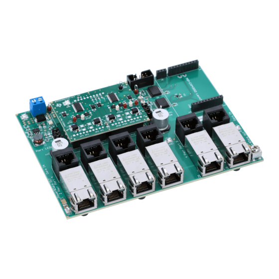
TPS23861EVM-612: Auto-Mode Evaluation Module for
This user's guide describes the evaluation modules (EVM) for the TPS23861 (TPS23861EVM-612). The
EVM contains evaluation and reference circuitry for the TPS23861. The TPS23861 is a Power-over-
Ethernet (PoE) device for power sourcing equipment (PSE).
....................................................................................................................
1
Description
....................................................................................................................
2
Quick Start
3
General Use Features
4
TPS23861EVM-612 PI Commander GUI Setup
5
EVM Schematic, Layout Guidelines and PCB Assembly, Layer Plots
6
Bill of Materials
Appendix A
Revision A Schematic
1
Basic Test Setup
2
Basic Setup Using USB-TO-GPIO
3
Advanced Setup Using LaunchPad
4
PI Commander Device Menu Window
5
PI Commander Device Selection Window
6
Devices Found in Scan
7
Detected Devices Selection
8
Device Selector Approval
9
Telemetry Page
10
PD Detection
11
Telemetry Data Collection and Graphs
12
Telemetry Data Collection and Graphs, Device 2
13
High-Level Status, 2 Devices
14
I2C Register Page
15
Device Configuration Page
16
Configuration Wizard
17
Hit 'S' to Start
18
Program Started
19
Terminal Response with Connected Ports
20
TPS23861 POE Documentation
21
TPS23861EVM-612 (Motherboard) Schematic: Control
22
TPS23861EVM-612 (Motherboard) Schematic: Power Ports
23
TPS23861EVM-613 (Daughterboard) Schematic
24
TPS23861EVM-612 (Motherboard) Top Side Assembly
25
TPS23861EVM-612 (Motherboard) Top Side Routing
26
TPS23861EVM-612 (Motherboard) Layer 2 Routing
27
TPS23861EVM-612 (Motherboard) Layer 3 Routing
SLUUAY8C – March 2014 – Revised November 2015
Submit Documentation Feedback
.......................................................................................................
.............................................................................................................
............................................................................................
.............................................................................................................
........................................................................................
.......................................................................................
...................................................................................
....................................................................................................
...............................................................................................
.................................................................................................
.............................................................................................................
................................................................................................................
..................................................................................
.............................................................................................
..........................................................................................................
................................................................................................
.......................................................................................................
...............................................................................................................
............................................................................................................
..........................................................................................
Copyright © 2014–2015, Texas Instruments Incorporated
SLUUAY8C – March 2014 – Revised November 2015
Contents
.......................................................................
..............................................
List of Figures
..............................................................................
......................................................................
..............................................................................
..............................................................
........................................................
......................................................................
..............................................................
................................................................
..................................................................
..................................................................
TPS23861EVM-612: Auto-Mode Evaluation Module for TPS23861
User's Guide
TPS23861
3
3
8
10
21
29
33
5
6
7
10
10
11
11
11
12
13
14
15
15
16
17
17
18
19
19
20
21
22
23
24
25
25
26
1
Advertisement

Related Manuals for Texas Instruments TPS23861EVM-612


Summary of Contents for Texas Instruments TPS23861EVM-612
- Page 1 TPS23861EVM-612: Auto-Mode Evaluation Module for TPS23861 This user’s guide describes the evaluation modules (EVM) for the TPS23861 (TPS23861EVM-612). The EVM contains evaluation and reference circuitry for the TPS23861. The TPS23861 is a Power-over- Ethernet (PoE) device for power sourcing equipment (PSE).
- Page 2 ......................EVM Test Points ........................ EVM Jumpers ..................TPS23861EVM-612 Bill of Materials ..................TPS23861EVM-613 Bill of Materials TPS23861EVM-612: Auto-Mode Evaluation Module for TPS23861 SLUUAY8C – March 2014 – Revised November 2015 Submit Documentation Feedback Copyright © 2014–2015, Texas Instruments Incorporated...
- Page 3 Description www.ti.com Description The TPS23861EVM-612 features the quad port, TPS23861, IEEE 802.3at PoE PSE controller. The EVM consists of a motherboard (TPS23861EVM-612) and daughter board (TPS23861EVM-613) containing two TPS23861 devices. The TPS23861EVM-612 provides a multi-port base platform interface for TPS23861EVM-613, MSP-EXP430G2 (LaunchPad™), and USB-TO-GPIO (USB Interface Adapter).
- Page 4 The TPS23861 devices are pre-configured to operate in auto mode and, as such, no external communication interface is required to enable or configure the TPS23861EVM-612. A standard PD can be plugged into ports 1–4 and be expected to operate automatically.
- Page 5 (44–57 VDC, 5 A), Ethernet patch cable, and any PD load. TPS23754EVM-420 Ethernet Cable TPS23861EVM-612 TPS23861EVM-613 Positive Negative Power Supply Figure 1. Basic Test Setup SLUUAY8C – March 2014 – Revised November 2015 TPS23861EVM-612: Auto-Mode Evaluation Module for TPS23861 Submit Documentation Feedback Copyright © 2014–2015, Texas Instruments Incorporated...
- Page 6 TPS23861EVM-612 TPS23861EVM-613 Ribbon Cable Positive Negative USB-to-GPIO Power Supply USB CABLE Figure 2. Basic Setup Using USB-TO-GPIO TPS23861EVM-612: Auto-Mode Evaluation Module for TPS23861 SLUUAY8C – March 2014 – Revised November 2015 Submit Documentation Feedback Copyright © 2014–2015, Texas Instruments Incorporated...
- Page 7 Ethernet Cable TPS23861EVM-612 TPS23861EVM-613 MSP-EXP430G2 USB CABLE Positive Negative Power Supply Figure 3. Advanced Setup Using LaunchPad SLUUAY8C – March 2014 – Revised November 2015 TPS23861EVM-612: Auto-Mode Evaluation Module for TPS23861 Submit Documentation Feedback Copyright © 2014–2015, Texas Instruments Incorporated...
- Page 8 Four-pair port 2A power is ON. For J9 supplier #1 (see the BOM), J9 internal port LED is active. For supplier #2, D14 is active. TPS23861EVM-612: Auto-Mode Evaluation Module for TPS23861 SLUUAY8C – March 2014 – Revised November 2015 Submit Documentation Feedback...
- Page 9 Four-pair port 2B LED bias Remove the jumpers listed in this table when doing SIFOS or UNH DC MPS testing. SLUUAY8C – March 2014 – Revised November 2015 TPS23861EVM-612: Auto-Mode Evaluation Module for TPS23861 Submit Documentation Feedback Copyright © 2014–2015, Texas Instruments Incorporated...
- Page 10 Follow the onscreen instructions to complete the installation. PI Commander uses the USB-TO-GPIO as an interface between the PC USB port and TPS23861EVM-612 J2 connector (I2C interface). Before starting PI Commander, make sure the USB-TO-GPIO is properly connected to TPS23861EVM-612 as...
- Page 11 Figure 7. Detected Devices Selection Once the following window pops up, click the OK button. Figure 8. Device Selector Approval SLUUAY8C – March 2014 – Revised November 2015 TPS23861EVM-612: Auto-Mode Evaluation Module for TPS23861 Submit Documentation Feedback Copyright © 2014–2015, Texas Instruments Incorporated...
- Page 12 Figure 9. Telemetry Page TPS23861EVM-612: Auto-Mode Evaluation Module for TPS23861 SLUUAY8C – March 2014 – Revised November 2015 Submit Documentation Feedback...
- Page 13 10, type two PDs are installed into ports 1, 2, 3, and 4 respectively and are successfully detected, classified, and powered up. Figure 10. PD Detection SLUUAY8C – March 2014 – Revised November 2015 TPS23861EVM-612: Auto-Mode Evaluation Module for TPS23861 Submit Documentation Feedback Copyright © 2014–2015, Texas Instruments Incorporated...
- Page 14 Clicking the Run button (blue arrow in the header bar) starts telemetry data collection and graphs (Figure 11). Figure 11. Telemetry Data Collection and Graphs TPS23861EVM-612: Auto-Mode Evaluation Module for TPS23861 SLUUAY8C – March 2014 – Revised November 2015 Submit Documentation Feedback Copyright © 2014–2015, Texas Instruments Incorporated...
- Page 15 The Dashboard window is also available showing a high level status (two devices shown). Figure 13. High-Level Status, 2 Devices SLUUAY8C – March 2014 – Revised November 2015 TPS23861EVM-612: Auto-Mode Evaluation Module for TPS23861 Submit Documentation Feedback Copyright © 2014–2015, Texas Instruments Incorporated...
- Page 16 (Figure 14) provides a detailed view of Status, Device, and Telemetry information. Figure 14. I2C Register Page TPS23861EVM-612: Auto-Mode Evaluation Module for TPS23861 SLUUAY8C – March 2014 – Revised November 2015 Submit Documentation Feedback Copyright © 2014–2015, Texas Instruments Incorporated...
- Page 17 The Configuration Wizard provides a quick way to set up ports in semi-auto or manual modes without much knowledge of the device register-specific details. Figure 16. Configuration Wizard SLUUAY8C – March 2014 – Revised November 2015 TPS23861EVM-612: Auto-Mode Evaluation Module for TPS23861 Submit Documentation Feedback Copyright © 2014–2015, Texas Instruments Incorporated...
- Page 18 HyperTerminal or Teraterm is required to view the output from the EVM when it is running. 4.3.1 Basic CCS and Terminal Setup 1. Launch the CCS program on the PC: Start → Texas Instruments → Code Composer Studio 5.3.0 → Code Composer Studio 5.3.0. 2. OK the workspace location and CCS starts 3.
- Page 19 11. Pressing the “S” key on the keyboard starts the program Figure 18. Program Started 12. The TPS23861EVM-612 is now waiting for a PD load to be installed. As ports are installed, the firmware automatically detects, classifies, and powers up the port as shown in the following image.
- Page 20 Documentation Figure 20 illustrates the documentation contained within the \POE- TPS23861\Document\doxy\html\index.html file. Figure 20. TPS23861 POE Documentation TPS23861EVM-612: Auto-Mode Evaluation Module for TPS23861 SLUUAY8C – March 2014 – Revised November 2015 Submit Documentation Feedback Copyright © 2014–2015, Texas Instruments Incorporated...
- Page 21 EVM Schematic, Layout Guidelines and PCB Assembly, Layer Plots www.ti.com EVM Schematic, Layout Guidelines and PCB Assembly, Layer Plots This section contains the TPS23861EVM-612 schematic, layout guidelines, and printed-circuit board (PCB) assembly and layer plots. Schematic Figure 21 through Figure 23 illustrate the TPS23861EVM-613 schematics.
- Page 22 4 Pair Port 1 SH-J6 SH-J7 SH-J8 PCB Rule 2200pF 2000V EARTH 7693 Figure 22. TPS23861EVM-612 (Motherboard) Schematic: Power Ports TPS23861EVM-612: Auto-Mode Evaluation Module for TPS23861 SLUUAY8C – March 2014 – Revised November 2015 Submit Documentation Feedback Copyright © 2014–2015, Texas Instruments Incorporated...
- Page 23 4 Pair Ports 1-2 VPWR VPWR PSE_N1 PSE_N5 PSE_N2 PSE_N6 PSE_N3 PSE_N4 PSE_N7 PSE_N8 1µF Figure 23. TPS23861EVM-613 (Daughterboard) Schematic SLUUAY8C – March 2014 – Revised November 2015 TPS23861EVM-612: Auto-Mode Evaluation Module for TPS23861 Submit Documentation Feedback Copyright © 2014–2015, Texas Instruments Incorporated...
- Page 24 Figure 24 through Figure 32 show the PCB layouts and assemblies for this EVM. Figure 24. TPS23861EVM-612 (Motherboard) Top Side Assembly TPS23861EVM-612: Auto-Mode Evaluation Module for TPS23861 SLUUAY8C – March 2014 – Revised November 2015 Submit Documentation Feedback Copyright © 2014–2015, Texas Instruments Incorporated...
- Page 25 EVM Schematic, Layout Guidelines and PCB Assembly, Layer Plots www.ti.com Figure 25. TPS23861EVM-612 (Motherboard) Top Side Routing Figure 26. TPS23861EVM-612 (Motherboard) Layer 2 Routing SLUUAY8C – March 2014 – Revised November 2015 TPS23861EVM-612: Auto-Mode Evaluation Module for TPS23861 Submit Documentation Feedback...
- Page 26 EVM Schematic, Layout Guidelines and PCB Assembly, Layer Plots www.ti.com Figure 27. TPS23861EVM-612 (Motherboard) Layer 3 Routing Figure 28. TPS23861EVM-612 (Motherboard) Bottom Side Routing TPS23861EVM-612: Auto-Mode Evaluation Module for TPS23861 SLUUAY8C – March 2014 – Revised November 2015 Submit Documentation Feedback...
- Page 27 EVM Schematic, Layout Guidelines and PCB Assembly, Layer Plots www.ti.com Figure 29. TPS23861EVM-613 (Daughterboard) Top Side Assembly Figure 30. TPS23861EVM-613 (Daughterboard) Top Side Routing SLUUAY8C – March 2014 – Revised November 2015 TPS23861EVM-612: Auto-Mode Evaluation Module for TPS23861 Submit Documentation Feedback Copyright © 2014–2015, Texas Instruments Incorporated...
- Page 28 EVM Schematic, Layout Guidelines and PCB Assembly, Layer Plots www.ti.com Figure 31. TPS23861EVM-613 (Daughterboard) Bottom Side Routing Figure 32. TPS23861EVM-613 (Daughterboard) Bottom Side Assembly TPS23861EVM-612: Auto-Mode Evaluation Module for TPS23861 SLUUAY8C – March 2014 – Revised November 2015 Submit Documentation Feedback Copyright © 2014–2015, Texas Instruments Incorporated...
- Page 29 Bill of Materials www.ti.com Bill of Materials The BOMs for the TPS23861EVM-612 and TPS23861EVM-613 are listed in Table 6 Table 7, respectively. Table 6. TPS23861EVM-612 Bill of Materials Designator Value Description Package Reference PartNumber Alternate Part Number Alternate MFR !PCB...
- Page 30 Bill of Materials www.ti.com Table 6. TPS23861EVM-612 Bill of Materials (continued) Designator Value Description Package Reference PartNumber Alternate Part Number Alternate MFR 6.04k RES, 6.04k ohm, 1%, 0.1W, 0603 0603 CRCW06036K04FKEA Vishay-Dale R10, R13 4.7k RES, 4.7k ohm, 5%, 0.1W, 0603...
- Page 31 Test Point, Compact, SMT Testpoint_Keystone_Comp 5016 Keystone U1, U2 QUAD IEEE 802.3at POWER-OVER-ETHERNET PSE CONTROLLER, PW0028A TPS23861PW Texas Instruments PW0028A SLUUAY8C – March 2014 – Revised November 2015 TPS23861EVM-612: Auto-Mode Evaluation Module for TPS23861 Submit Documentation Feedback Copyright © 2014–2015, Texas Instruments Incorporated...
- Page 32 Bill of Materials www.ti.com TPS23861EVM-612: Auto-Mode Evaluation Module for TPS23861 SLUUAY8C – March 2014 – Revised November 2015 Submit Documentation Feedback Copyright © 2014–2015, Texas Instruments Incorporated...
- Page 33 Appendix A SLUUAY8C – March 2014 – Revised November 2015 Revision A Schematic Figure 33 illustrates the revision A, TPS23861EVM-612 (Motherboard) schematic. VPWR VPWR 82µH SDR0805-820KL 3.3V RON/SD 3.3V 200k 0.01µF 1.00 INPUT POWER Green 1.00k 44–57 VDC LM5007MM/NOPB SMCJ58A-13-F 0.1µF...
- Page 34 Added table note on EVM Jumpers table and changed labels column from P0–P7 to P1–P8................• Changed path for PI Commander start instructions............ • Changed TPS23861EVM-612 (Motherboard) Schematic: Control to Rev. B................. • Changed PCB Motherboard images, figures 24–28....................•...
- Page 35 STANDARD TERMS AND CONDITIONS FOR EVALUATION MODULES Delivery: TI delivers TI evaluation boards, kits, or modules, including any accompanying demonstration software, components, or documentation (collectively, an “EVM” or “EVMs”) to the User (“User”) in accordance with the terms and conditions set forth herein. Acceptance of the EVM is expressly subject to the following terms and conditions.
- Page 36 FCC Interference Statement for Class B EVM devices NOTE: This equipment has been tested and found to comply with the limits for a Class B digital device, pursuant to part 15 of the FCC Rules. These limits are designed to provide reasonable protection against harmful interference in a residential installation.
- Page 37 【無線電波を送信する製品の開発キットをお使いになる際の注意事項】 開発キットの中には技術基準適合証明を受けて いないものがあります。 技術適合証明を受けていないもののご使用に際しては、電波法遵守のため、以下のいずれかの 措置を取っていただく必要がありますのでご注意ください。 1. 電波法施行規則第6条第1項第1号に基づく平成18年3月28日総務省告示第173号で定められた電波暗室等の試験設備でご使用 いただく。 2. 実験局の免許を取得後ご使用いただく。 3. 技術基準適合証明を取得後ご使用いただく。 なお、本製品は、上記の「ご使用にあたっての注意」を譲渡先、移転先に通知しない限り、譲渡、移転できないものとします。 上記を遵守頂けない場合は、電波法の罰則が適用される可能性があることをご留意ください。 日本テキサス・イ ンスツルメンツ株式会社 東京都新宿区西新宿6丁目24番1号 西新宿三井ビル 3.3.3 Notice for EVMs for Power Line Communication: Please see http://www.tij.co.jp/lsds/ti_ja/general/eStore/notice_02.page 電力線搬送波通信についての開発キットをお使いになる際の注意事項については、次のところをご覧くださ い。http://www.tij.co.jp/lsds/ti_ja/general/eStore/notice_02.page SPACER EVM Use Restrictions and Warnings: 4.1 EVMS ARE NOT FOR USE IN FUNCTIONAL SAFETY AND/OR SAFETY CRITICAL EVALUATIONS, INCLUDING BUT NOT LIMITED TO EVALUATIONS OF LIFE SUPPORT APPLICATIONS.
- Page 38 Notwithstanding the foregoing, any judgment may be enforced in any United States or foreign court, and TI may seek injunctive relief in any United States or foreign court. Mailing Address: Texas Instruments, Post Office Box 655303, Dallas, Texas 75265 Copyright © 2015, Texas Instruments Incorporated...
- Page 39 IMPORTANT NOTICE Texas Instruments Incorporated and its subsidiaries (TI) reserve the right to make corrections, enhancements, improvements and other changes to its semiconductor products and services per JESD46, latest issue, and to discontinue any product or service per JESD48, latest issue.
Need help?
Do you have a question about the TPS23861EVM-612 and is the answer not in the manual?
Questions and answers