
Related Manuals for Texas Instruments TPS2375EVM


Summary of Contents for Texas Instruments TPS2375EVM
- Page 1 TPS2375EVM Power Over Ethernet Powered Device (PD) Evaluation Module User’s Guide April 2004 PMP Systems Power SLVU108 This datasheet has been downloaded from http://www.digchip.com at this page...
- Page 2 TI product or service and is an unfair and deceptive business practice. TI is not responsible or liable for any such statements. Following are URLs where you can obtain information on other Texas Instruments products and application solutions:...
- Page 3 EVM IMPORTANT NOTICE Texas Instruments (TI) provides the enclosed product(s) under the following conditions: This evaluation kit being sold by TI is intended for use for ENGINEERING DEVELOPMENT OR EVALUATION PURPOSES ONLY and is not considered by TI to be fit for commercial use. As such, the goods being provided may not be complete in terms of required design-, marketing-, and/or manufacturing-related protective considerations, including product safety measures typically found in the end product incorporating the goods.
- Page 4 EVM schematic located in the EVM User’s Guide. When placing measurement probes near these devices during operation, please be aware that these devices may be very warm to the touch. Mailing Address: Texas Instruments Post Office Box 655303 Dallas, Texas 75265 Copyright 2004, Texas Instruments Incorporated...
- Page 5 Information About Cautions and Warnings Preface Read This First About This Manual This user’s guide describes the TPS2375 HPA028 evaluation module (EVM). It contains the EVM schematic, bill of materials, assembly drawing, and top and bottom board layouts. How to Use This Manual This document contains the following chapters: Chapter 1 —...
- Page 6 Related Documentation From Texas Instruments The information in a caution or a warning is provided for your protection. Please read each caution and warning carefully. Related Documentation From Texas Instruments TPS2375 Power Over Ethernet Powered Device Power Switch − data sheet,...
-
Page 7: Table Of Contents
Contents Contents Introduction ..............Hardware Overview . - Page 8 Contents viii...
-
Page 9: Introduction
Chapter 1 Introduction This User’s Guide describes the setup and operation of the TPS2375 HPA028 evaluation module (EVM). Information and instructions presented throughout this document assumes user familiarity with the IEEE 802.3af Specification for Power Over Ethernet. Introduction... - Page 10 (This page has been left blank intentionally.)
-
Page 11: Hardware Overview
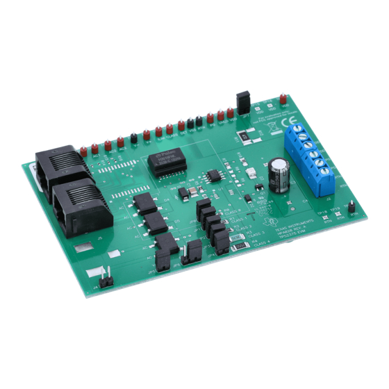
Chapter 2 Hardware Overview The HPA028 EVM features the TPS2375 made by Texas Instruments Incorporated. The EVM is designed to look like the front end of any Power Over Ethernet (PoE) Powered Device (PD) module. An RJ-45 connector is provided to connect directly to an Ethernet cable having a Power Sourcing Equipment (PSE) driving it on the other end. - Page 12 (This page has been left blank intentionally.)
-
Page 13: Evm Operation
Chapter 3 EVM Operation This chapter discusses the EVM operation including setup, jumpers, test points and features. Topic Page Setup ............Jumpers . -
Page 14: Setup
Setup 3.1 Setup The HPA028 EVM is designed to allow evaluation of the TPS2375 device. Test points and jumpers are provided to facilitate testing and configuration. At the factory, JP0, JP5, JP6 (between pin 2 and pin 3), and JP7 will be installed. 3.2 Jumpers JP0, JP1, JP2, JP3, JP4 Selects the Classification Resistor... -
Page 15: Features
Features 3.4 Features The HPA028 EVM facilitates easy evaluation of the TPS2375 PD controller. The EVM features are described in this section. 3.4.1 Input and Output Capacitors The input capacitor of the TPS2375 PD controller is specified by the IEEE802.3af standard. C1, a 0.1 µF ±10% ceramic capacitor, meets the IEEE specification, so no additional input capacitor can be added. -
Page 16: Available Spare Footprints
Features 3.4.6 Available Spare Footprints TP15, TP16 – extra test points for 48-V positive rail (VDD) TP18, TP19 − extra test points for 48-V load-side return (RTN) J5 – Jack for connecting an external wall-mounted transformer power sup- ply; R8, R9 – To set the UVLO threshold if a TPS2376 is under test; R12 –... -
Page 17: Bill Of Materials
Chapter 4 Bill of Materials This chapter contains the bill of materials for the TPS2375EVM. Topic Page Bill of Materials .......... -
Page 18: Bill Of Materials
Bill of Materials 4.1 Bill of Materials Count RefDes Description Size Part Number Diode, 58-V TVS, SMAJ58A Vishay Diode, 5.6 V Zener D0−219AB BZD27C5V6P Vishay LED, SMD, Green, PLCC2−Package 1210 TLMG3102 Vishay D4, D5, D6 Bridge Rectifier, 100 V, 1A, SMD DF−S DF01S Vishay... - Page 19 Bill of Materials Count RefDes Description Size Part Number IC, TPS2375 Powered Device TSSOP−8 TPS2375PW Controller IC, TPS2375 Powered Device SO−8 TPS2375D Controller Shunt on JP0,JP5, JP6, & JP7, 2−pin, STC02SYAN Sullins 0.100 cntr PCB, 4.316 In × 2.890 In × 0.062 In −−...
-
Page 21: Schematic And Layout
Chapter 5 Schematic and Layout This chapter contains the schematic and layout for the TPS2375EVM. Topic Page Schematic ........... . -
Page 22: Tps2375 Evm Schematic
TPS2375 EVM Schematic 5.1 TPS2375 EVM Schematic... -
Page 23: Layouts
Layouts 5.2 Layouts The board layout is shown on the following pages. Schematic and Layout... - Page 24 Layouts Figure 5−1. Top Assembly Layer...
- Page 25 Layouts Figure 5−2. Bottom Assembly Layer Schematic and Layout...
Need help?
Do you have a question about the TPS2375EVM and is the answer not in the manual?
Questions and answers