Table of Contents
Advertisement
Quick Links
www.ti.com
EVM User's Guide: TPS25772Q1EVM-CD-150
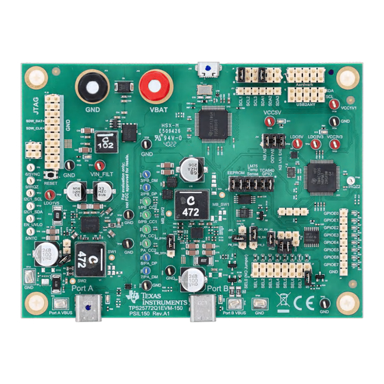
TPS25772-Q1 USB PD + USB 2.0 Evaluation Module
Description
The TPS25772Q1EVM-CD-150 is designed to
evaluate the TPS25772-Q1 for USB Type-C
and Power Delivery (PD) applications. This EVM
supports dual PD charging ports + USB 2.0
and comes with three other variants: single port
charging with DisplayPort
Mode) (TPS25763Q1EVM), single port charging
only (TPS25762DQ1EVM), and dual ports charging
only (TPS25772DQ1EVM). The EVM integrates a
TIVA microcontroller and HUB IC, enabling online
debugging, online EEPROM updates, and dual ports
USB 2.0 data support.
Device configuration settings are selected through an
intuitive Application Customization Tool in the form
of a graphical user interface (TPS257XX-Q1-GUI),
reducing much of the complexity associated with
competitive USB-PD designs.
Get Started
1. Read this TPS25772Q1EVM-CD-150 user's guide
2. Start development with the Graphical User
Interface (TPS257XX-Q1-GUI)
SLVUD10A – AUGUST 2024 – REVISED SEPTEMBER 2024
Submit Document Feedback
®
™
®
over USB-C
(DP Alt
TPS25772Q1EVM-CD-150
Copyright © 2024 Texas Instruments Incorporated
3. Refer to the
TPS25772-Q1 data sheet
questions and support
Features
•
TPS25772-Q1: USB-IF certification with PPS, TID:
9161
•
Charging up to 65W on Port A
•
Supports 65W charging on Port B with the
TPS55288-Q1
•
Easy-to-use GUI with preconfigured firmware to
configure device
•
VBUS and CCx test points for both Type-C ports to
monitor PD traffic
•
MCU for EEPROM programming and system
telemetry
•
Jumper configuration of all system configurable
pins
Applications
•
Automotive USB Charging
•
Automotive Media Hub
•
Automotive Head Unit
•
Automotive Rear Seat Entertainment
TPS25772-Q1 USB PD + USB 2.0 Evaluation Module
Description
or
E2E
for
1
Advertisement
Table of Contents

Related Manuals for Texas Instruments TPS25772Q1EVM-CD-150


Summary of Contents for Texas Instruments TPS25772Q1EVM-CD-150
- Page 1 Automotive USB Charging • Automotive Media Hub Get Started • Automotive Head Unit 1. Read this TPS25772Q1EVM-CD-150 user's guide • Automotive Rear Seat Entertainment 2. Start development with the Graphical User Interface (TPS257XX-Q1-GUI) TPS25772Q1EVM-CD-150 SLVUD10A – AUGUST 2024 – REVISED SEPTEMBER 2024 TPS25772-Q1 USB PD + USB 2.0 Evaluation Module...
-
Page 2: Kit Contents
USB2ANY interface for debugging and development. This user's guide describes how the TPS25772Q1EVM-CD-150 can be used to test PD functions as well as USB data. This document includes descriptions of how to use the EVM, contents, schematics, printed circuit board (PCB) layouts, and bill of materials (BOM). -
Page 3: Device Information
Evaluation Module Overview 1.4 Device Information The purpose of the TPS25772Q1EVM-CD-150 is to showcase the hardware and firmware capabilities of the TPS25772-Q1 device. The other components on the board are populated for testing and support of the main device. -
Page 4: Evm Operation
• Notebook with USB 2.0 capabilities Figure 2-1 shows how to power and set up the TPS25772Q1EVM-CD-150 for evaluation and testing. Figure 2-1. EVM Connections TPS25772-Q1 USB PD + USB 2.0 Evaluation Module SLVUD10A – AUGUST 2024 – REVISED SEPTEMBER 2024 Submit Document Feedback Copyright ©... - Page 5 2.3.1 Jumper Settings This section goes over the jumper settings of the EVM. To reference the default jumper configurations, see Table 2-1. Table 2-1. TPS25772Q1EVM-CD-150 Configuration for Basic Operation Jumper Connection Description Jumper not installed NTC not connected to onboard PTC or I2C digital potentiometer...
-
Page 6: Power Supply Control
The I2C Connection headers and jumper settings are shown in Figure 2-4 and described in Table 2-4. Figure 2-4. J6 I2C Connection Header Block TPS25772-Q1 USB PD + USB 2.0 Evaluation Module SLVUD10A – AUGUST 2024 – REVISED SEPTEMBER 2024 Submit Document Feedback Copyright © 2024 Texas Instruments Incorporated... - Page 7 Leave open to connect the EN pin of the TPS55288-Q1 to a resistor divider from VIN. The R97 and R99 resistors are DNP by default SLVUD10A – AUGUST 2024 – REVISED SEPTEMBER 2024 TPS25772-Q1 USB PD + USB 2.0 Evaluation Module Submit Document Feedback Copyright © 2024 Texas Instruments Incorporated...
- Page 8 Connect PTC resistors to TPS25772-Q1 NTC pin NTC VAR Connect the I2C digital potentiometer to the NTC pin TPS25772-Q1 USB PD + USB 2.0 Evaluation Module SLVUD10A – AUGUST 2024 – REVISED SEPTEMBER 2024 Submit Document Feedback Copyright © 2024 Texas Instruments Incorporated...
- Page 9 The D+ and D- signals of Port B are directly connected to the Micro-B receptacle via the U13 HUB. SLVUD10A – AUGUST 2024 – REVISED SEPTEMBER 2024 TPS25772-Q1 USB PD + USB 2.0 Evaluation Module Submit Document Feedback Copyright © 2024 Texas Instruments Incorporated...
- Page 10 5V supply from the Aardvark connection. Not used on the EVM, but present for potential use in Aard1_5V debug. N.C. No connection N.C. No connection N.C. No connection Ground reference TPS25772-Q1 USB PD + USB 2.0 Evaluation Module SLVUD10A – AUGUST 2024 – REVISED SEPTEMBER 2024 Submit Document Feedback Copyright © 2024 Texas Instruments Incorporated...
-
Page 11: Push Buttons
GUI and the process to program the resulting configuration into the EEPROM connected to the TPS25772-Q1. SLVUD10A – AUGUST 2024 – REVISED SEPTEMBER 2024 TPS25772-Q1 USB PD + USB 2.0 Evaluation Module Submit Document Feedback Copyright © 2024 Texas Instruments Incorporated... - Page 12 I2C_SDA2 USB4085-GF-A USB4085-GF-A P B_D_P PA_D_P CONN_P B_D_P CONN_PA_D_P Figure 4-1. EVM Top Level Schematic TPS25772-Q1 USB PD + USB 2.0 Evaluation Module SLVUD10A – AUGUST 2024 – REVISED SEPTEMBER 2024 Submit Document Feedback Copyright © 2024 Texas Instruments Incorporated...
- Page 13 14.3k 0.022uF TP S 55288QRP MRQ1 150k 20.0k 100pF 4700pF AGND Figure 4-2. TPS55288-Q1 Schematic SLVUD10A – AUGUST 2024 – REVISED SEPTEMBER 2024 TPS25772-Q1 USB PD + USB 2.0 Evaluation Module Submit Document Feedback Copyright © 2024 Texas Instruments Incorporated...
- Page 14 47.0k 6.3V 10µF 10µF 0.01uF 47.0k TP S 74601P BQWDRVRQ1 Figure 4-3. EVM Power System TPS25772-Q1 USB PD + USB 2.0 Evaluation Module SLVUD10A – AUGUST 2024 – REVISED SEPTEMBER 2024 Submit Document Feedback Copyright © 2024 Texas Instruments Incorporated...
- Page 15 SH-J10 I2C_SDA2 VS S I2C_SDA3 TPL0102-100RUCR P EC06S AAN SH-J11 Figure 4-4. TPS25772-Q1 Schematic Peripherals SLVUD10A – AUGUST 2024 – REVISED SEPTEMBER 2024 TPS25772-Q1 USB PD + USB 2.0 Evaluation Module Submit Document Feedback Copyright © 2024 Texas Instruments Incorporated...
- Page 16 0.1µF 0.1µF 0.1µF 0.1µF 0.1µF 0.1µF 0.1µF 0.1µF 0.1µF 0.1µF 0.1µF Figure 4-5. USB HUB TPS25772-Q1 USB PD + USB 2.0 Evaluation Module SLVUD10A – AUGUST 2024 – REVISED SEPTEMBER 2024 Submit Document Feedback Copyright © 2024 Texas Instruments Incorporated...
- Page 17 P B5 GNDX P B6 GNDA P B7 TM4C123GH6PMTR Figure 4-6. TIVA USB 2 I2C MCU SLVUD10A – AUGUST 2024 – REVISED SEPTEMBER 2024 TPS25772-Q1 USB PD + USB 2.0 Evaluation Module Submit Document Feedback Copyright © 2024 Texas Instruments Incorporated...
- Page 18 TP D1E05U06QDPYRQ1 C110 R135 C111 R136 220nF 10.0k 220nF 10.0k Figure 4-7. EVM IEC ESD Protection TPS25772-Q1 USB PD + USB 2.0 Evaluation Module SLVUD10A – AUGUST 2024 – REVISED SEPTEMBER 2024 Submit Document Feedback Copyright © 2024 Texas Instruments Incorporated...
- Page 19 100nF VCAP CA T HODE LM74700QDBVRQ1 Figure 4-8. EVM 12V Input and EMC Power Filter SLVUD10A – AUGUST 2024 – REVISED SEPTEMBER 2024 TPS25772-Q1 USB PD + USB 2.0 Evaluation Module Submit Document Feedback Copyright © 2024 Texas Instruments Incorporated...
-
Page 20: Pcb Layouts
4.2 PCB Layouts Figure 4-9. Top View Composite View Figure 4-10. Bottom View Composite View TPS25772-Q1 USB PD + USB 2.0 Evaluation Module SLVUD10A – AUGUST 2024 – REVISED SEPTEMBER 2024 Submit Document Feedback Copyright © 2024 Texas Instruments Incorporated... - Page 21 Hardware Design Files Figure 4-11. Top Solder Mask Figure 4-12. Bottom Solder Mask SLVUD10A – AUGUST 2024 – REVISED SEPTEMBER 2024 TPS25772-Q1 USB PD + USB 2.0 Evaluation Module Submit Document Feedback Copyright © 2024 Texas Instruments Incorporated...
- Page 22 Hardware Design Files www.ti.com Figure 4-13. Top Layer(1) Figure 4-14. Signal Layer(2) TPS25772-Q1 USB PD + USB 2.0 Evaluation Module SLVUD10A – AUGUST 2024 – REVISED SEPTEMBER 2024 Submit Document Feedback Copyright © 2024 Texas Instruments Incorporated...
- Page 23 Hardware Design Files Figure 4-15. Signal Layer(3) Figure 4-16. Bottom Layer (4) SLVUD10A – AUGUST 2024 – REVISED SEPTEMBER 2024 TPS25772-Q1 USB PD + USB 2.0 Evaluation Module Submit Document Feedback Copyright © 2024 Texas Instruments Incorporated...
- Page 24 Hardware Design Files www.ti.com 4.3 Bill of Materials (BOM) The bill of materials for the TPS25772Q1EVM-CD-150 is listed in Table 4-1. Table 4-1. TPS25772Q1EVM-CD-150 Bill of Materials Package Alternate Part Alternate Designator Quantity Value Description Part Number Manufacturer Reference Number...
- Page 25 Hardware Design Files Table 4-1. TPS25772Q1EVM-CD-150 Bill of Materials (continued) Package Alternate Part Alternate Designator Quantity Value Description Part Number Manufacturer Reference Number Manufacturer CAP, CERM, 1uF, 35V, +/- 10%, CGA3E1X7R1V105K080AC TDK X7R, AEC-Q200 Grade 1, 0603 C46, C47, C48, 10uF CAP, CERM, 10µF, 6.3V,+/- 20%,...
- Page 26 Hardware Design Files www.ti.com Table 4-1. TPS25772Q1EVM-CD-150 Bill of Materials (continued) Package Alternate Part Alternate Designator Quantity Value Description Part Number Manufacturer Reference Number Manufacturer 28.2V Diode, TVS, Bi, 22V, 35.5 Vc, AEC- P6SMB33CA Littelfuse Q101, SMC D10, D11, D12,...
- Page 27 Hardware Design Files Table 4-1. TPS25772Q1EVM-CD-150 Bill of Materials (continued) Package Alternate Part Alternate Designator Quantity Value Description Part Number Manufacturer Reference Number Manufacturer 1.5uH Inductor, Shielded, Ferrite, 1.5uH, Inductor, SRP5030T-1R5M Bourns 6A, 0.025 ohm, SMD 5.7x2.8x5.2mm PORT A1, USB - C (Type - C) USB 2.0...
- Page 28 Hardware Design Files www.ti.com Table 4-1. TPS25772Q1EVM-CD-150 Bill of Materials (continued) Package Alternate Part Alternate Designator Quantity Value Description Part Number Manufacturer Reference Number Manufacturer 26.7k RES, 26.7 k, 1%, 0.063 W, AEC- CRCW040226K7FKED Vishay-Dale Q200 Grade 0, 0402 18.2k RES, 18.2 k, 1%, 0.063 W, AEC-...
- Page 29 Hardware Design Files Table 4-1. TPS25772Q1EVM-CD-150 Bill of Materials (continued) Package Alternate Part Alternate Designator Quantity Value Description Part Number Manufacturer Reference Number Manufacturer R80, R81, R83, 10.0k RES, 10.0 k, 1%, 0.063 W, AEC- AC0402FR-0710KL Yageo America R88, R93, R94,...
- Page 30 Hardware Design Files www.ti.com Table 4-1. TPS25772Q1EVM-CD-150 Bill of Materials (continued) Package Alternate Part Alternate Designator Quantity Value Description Part Number Manufacturer Reference Number Manufacturer TP6, TP7, Test Point, Miniature, Green, TH Green Miniature 5116 Keystone TP18, TP19 Test point...
- Page 31 Hardware Design Files Table 4-1. TPS25772Q1EVM-CD-150 Bill of Materials (continued) Package Alternate Part Alternate Designator Quantity Value Description Part Number Manufacturer Reference Number Manufacturer Automotive Catalog ESD Protected, RSE0010A TS3USB221AQRSERQ1 Texas Instruments High-Speed USB 2.0 (480Mbps) 1:2 Multiplexer / Demultiplexer Switch, 16 ohm RON, 2.5 to 3.3V, -40 to 125...
- Page 32 Hardware Design Files www.ti.com Table 4-1. TPS25772Q1EVM-CD-150 Bill of Materials (continued) Package Alternate Part Alternate Designator Quantity Value Description Part Number Manufacturer Reference Number Manufacturer R1, R2 RES, 2.2, 5%, 0.125 W, AEC-Q200 ERJ-6GEYJ2R2V Panasonic Grade 0, 0805 RES, 0, 5%, 0.063 W, 0402...
-
Page 33: Additional Information
Page • Updated document status from private to public....................• Updated document title for clarity........................SLVUD10A – AUGUST 2024 – REVISED SEPTEMBER 2024 TPS25772-Q1 USB PD + USB 2.0 Evaluation Module Submit Document Feedback Copyright © 2024 Texas Instruments Incorporated... - Page 34 TI products. TI’s provision of these resources does not expand or otherwise alter TI’s applicable warranties or warranty disclaimers for TI products. TI objects to and rejects any additional or different terms you may have proposed. IMPORTANT NOTICE Mailing Address: Texas Instruments, Post Office Box 655303, Dallas, Texas 75265 Copyright © 2024, Texas Instruments Incorporated...
Need help?
Do you have a question about the TPS25772Q1EVM-CD-150 and is the answer not in the manual?
Questions and answers