Table of Contents
Advertisement
Quick Links
Advertisement
Table of Contents

Subscribe to Our Youtube Channel
Related Manuals for Rohde & Schwarz TS-PSU12


Summary of Contents for Rohde & Schwarz TS-PSU12
- Page 1 ® R&S TS-PSU12 Power Supply/Load Module 12V User Manual (?4]H<) 1504.4524.12 ─ 05...
- Page 2 Subject to change – Data without tolerance limits is not binding. ® R&S is a registered trademark of Rohde & Schwarz GmbH & Co. KG. Trade names are trademarks of the owners. ® The following abbreviations are used throughout this manual: R&S TS-PSU12 is abbreviated as R&S TS-PSU12.
-
Page 3: Basic Safety Instructions
Basic Safety Instructions Always read through and comply with the following safety instructions! All plants and locations of the Rohde & Schwarz group of companies make every effort to keep the safety standards of our products up to date and to offer our customers the highest possible degree of safety. Our products and the auxiliary equipment they require are designed, built and tested in accordance with the safety standards that apply in each case. - Page 4 Basic Safety Instructions Symbol Meaning Symbol Meaning Caution ! Hot surface Alternating current (AC) Protective conductor terminal Direct/alternating current (DC/AC) To identify any terminal which is intended for connection to an external conductor for protection against electric shock in case of a fault, or the terminal of a protective earth Earth (Ground) Class II Equipment...
- Page 5 Basic Safety Instructions Operating states and operating positions The product may be operated only under the operating conditions and in the positions specified by the manufacturer, without the product's ventilation being obstructed. If the manufacturer's specifications are not observed, this can result in electric shock, fire and/or serious personal injury or death. Applicable local or national safety regulations and rules for the prevention of accidents must be observed in all work performed.
- Page 6 Basic Safety Instructions 6. The product may be operated only from TN/TT supply networks fuse-protected with max. 16 A (higher fuse only after consulting with the Rohde & Schwarz group of companies). 7. Do not insert the plug into sockets that are dusty or dirty. Insert the plug firmly and all the way into the socket provided for this purpose.
- Page 7 Basic Safety Instructions 2. Before you move or transport the product, read and observe the section titled "Transport". 3. As with all industrially manufactured goods, the use of substances that induce an allergic reaction (allergens) such as nickel cannot be generally excluded. If you develop an allergic reaction (such as a skin rash, frequent sneezing, red eyes or respiratory difficulties) when using a Rohde &...
- Page 8 Basic Safety Instructions 2. Adjustments, replacement of parts, maintenance and repair may be performed only by electrical experts authorized by Rohde & Schwarz. Only original parts may be used for replacing parts relevant to safety (e.g. power switches, power transformers, fuses). A safety test must always be performed after parts relevant to safety have been replaced (visual inspection, protective conductor test, insulation resistance measurement, leakage current measurement, functional test).
-
Page 9: Instrucciones De Seguridad Elementales
Instrucciones de seguridad elementales Waste disposal/Environmental protection 1. Specially marked equipment has a battery or accumulator that must not be disposed of with unsorted municipal waste, but must be collected separately. It may only be disposed of at a suitable collection point or via a Rohde &... - Page 10 Instrucciones de seguridad elementales Se parte del uso correcto del producto para los fines definidos si el producto es utilizado conforme a las indicaciones de la correspondiente documentación del producto y dentro del margen de rendimiento definido (ver hoja de datos, documentación, informaciones de seguridad que siguen). El uso del producto hace necesarios conocimientos técnicos y ciertos conocimientos del idioma inglés.
- Page 11 Instrucciones de seguridad elementales Símbolo Significado Símbolo Significado Aviso: Cuidado en el manejo de dispositivos Distintivo de la UE para la eliminación por sensibles a la electrostática (ESD) separado de dispositivos eléctricos y electrónicos Más información en la sección "Eliminación/protección del medio ambiente", punto 2.
- Page 12 Instrucciones de seguridad elementales 1. Si no se convino de otra manera, es para los productos Rohde & Schwarz válido lo que sigue: como posición de funcionamiento se define por principio la posición con el suelo de la caja para abajo, modo de protección IP 2X, uso solamente en estancias interiores, utilización hasta 2000 m sobre el nivel del mar, transporte hasta 4500 m sobre el nivel del mar.
- Page 13 Instrucciones de seguridad elementales 6. Solamente está permitido el funcionamiento en redes de alimentación TN/TT aseguradas con fusibles de 16 A como máximo (utilización de fusibles de mayor amperaje solo previa consulta con el grupo de empresas Rohde & Schwarz). 7.
- Page 14 Instrucciones de seguridad elementales Funcionamiento 1. El uso del producto requiere instrucciones especiales y una alta concentración durante el manejo. Debe asegurarse que las personas que manejen el producto estén a la altura de los requerimientos necesarios en cuanto a aptitudes físicas, psíquicas y emocionales, ya que de otra manera no se pueden excluir lesiones o daños de objetos.
- Page 15 Instrucciones de seguridad elementales Reparación y mantenimiento 1. El producto solamente debe ser abierto por personal especializado con autorización para ello. Antes de manipular el producto o abrirlo, es obligatorio desconectarlo de la tensión de alimentación, para evitar toda posibilidad de choque eléctrico. 2.
- Page 16 Instrucciones de seguridad elementales 2. Las asas instaladas en los productos sirven solamente de ayuda para el transporte del producto por personas. Por eso no está permitido utilizar las asas para la sujeción en o sobre medios de transporte como p. ej. grúas, carretillas elevadoras de horquilla, carros etc. Es responsabilidad suya fijar los productos de manera segura a los medios de transporte o elevación.
- Page 17 Quality management Certified Quality System ISO 9001 and environmental Certified Environmental System management ISO 14001 Sehr geehrter Kunde, Dear customer, Cher client, Sie haben sich für den Kauf You have decided to buy a Vous avez choisi d’acheter un eines Rohde & Schwarz Produk- Rohde &...
-
Page 18: Customer Support
Customer Support Technical support – where and when you need it For quick, expert help with any Rohde & Schwarz equipment, contact one of our Customer Support Centers. A team of highly qualified engineers provides telephone support and will work with you to find a solution to your query on any aspect of the operation, programming or applications of Rohde &... -
Page 19: Description Of Product
(CompactPCI or PXI modules). 1.2 Description of Product The Power Supply/Load Module 12V R&S TS-PSU12 is a module based on Com- pactPCI developed for use on the ROHDE & SCHWARZ R&S CompactTSVP and R&S PowerTSVP production test platform. -
Page 20: Safety Instructions
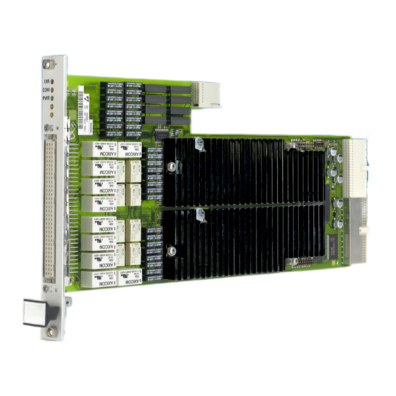
1.5 Safety instructions The R&S CompactTSVP/ R&S PowerTSVP production platform and the Power Supply/ Load Module 12V R&S TS-PSU12 are designed so that users can operate at voltages up to 125 V. The requirements according to EN61010-1 for operation with “hazardous live”... - Page 21 ® View R&S TS-PSU12 2 View Figure 2-1 Figure 2-2 show views of the two modules of Power Supply/Load Mod- ule 12V R&S TS-PSU12. Figure 2-1: PSU power module view User Manual 1504.4524.12 ─ 05...
- Page 22 ® View R&S TS-PSU12 Figure 2-2: Ansicht des Rear-I/O Moduls R&S TS-PDC The Module R&S TS-PDC exists in 3 different models: ● Grouted in a black housing - version up to 1.8 (1157.9804.02 obsolete) ● Encapsulated in metal housing with cooling fins - version 1.9 (1157.9804.02 obsolete)
-
Page 23: Block Diagram
R&S TS-PSU12 3 Block Diagram Figure 3-1 shows a simplified functional block diagram of the Power Supply/Load Mod- ule 12V R&S TS-PSU12. This functional block diagram represents the modules of the R&S TS-PSU12. ● PSU power module ● Rear-I/O module R&S TS-PDC Figure 3-2 shows a block diagram of the Power Supply/Load Module 12V R&S TS-... - Page 24 ® Block Diagram R&S TS-PSU12 Figure 3-1: Functional block diagram R&S TS-PSU12 User Manual 1504.4524.12 ─ 05...
- Page 25 ® Block Diagram R&S TS-PSU12 Figure 3-2: Block diagram R&S TS-PSU12 User Manual 1504.4524.12 ─ 05...
- Page 26 ® Layout R&S TS-PSU12 Mechanical layout PSU power module 4 Layout 4.1 Mechanical layout PSU power module The PSU power module is designed as a long plug-in card for front side insertion in the R&S CompactTSVP production test platform or in the R&S PowerTSVP production test platform.
-
Page 27: Display Elements
Error status: (red) Lit or flashing if an error occurs during the power on test on the R&S TS-PSU12 module after the power supply is turned on. This means there is a hardware problem in the mod- ule. (See also Chapter 8, "Self-Test",... - Page 28 The R&S TS-PDC module must always use the corresponding rear I/O slot for the main module. The R&S TS-PDC module must always be inserted in the corresponding rear I/O slot of the R&S TS-PSU12 module. If modules are inserted incorrectly (e.g. cPCI/PXI standard modules in the front), both modules may be damaged irreparably.
- Page 29 ® Layout R&S TS-PSU12 Display elements of the R&S TS-PDC Module Figure 4-3: Arrangement of the connector and LEDs on the R&S TS-PDC module Table 4-3: Connector for the R&S TS-PDC module Symbol Extension (Rear I/O) 4.4 Display elements of the R&S TS-PDC Module 4.4.1 R&S TS-PDC Version lower than 2.0 (1157.9804.02)
- Page 30 ® Layout R&S TS-PSU12 Display elements of the R&S TS-PDC Module Figure 4-4: LEDs on the R&S TS-PDC module from Version 2.0 User Manual 1504.4524.12 ─ 05...
-
Page 31: Function Description
Figure 5-1: Block diagram of channels 5.2 Power supply/load unit The Power Supply/Load Module 12V R&S TS-PSU12 is designed as a 4- quadrant source consisting of a 2-quadrant output stage followed by a polarity switch. The out- put stage consists of a linear regulator with current and voltage feedback. The linear regulator receives its power through the PSU-AC/DC converter. - Page 32 R&S TS-PSU12. This may increase the voltage at the output to rise to the level of the exter- nal source, but not beyond the range (12 V).
-
Page 33: Characteristic Diagram
The maximum voltage or current values are determined by the characteristic data of the R&S TS-PSU12. In addition to the absolute limits 12 V and 0,5 A, a maximum out- put power (CURRENT_LIMIT * VOLTAGE_LEVEL) of 5 W must not be exceeded in source operation and 6 W in sink mode (continuous operation). -
Page 34: Inductive Loads
To compensate for voltage drops in the line to the external load or source, the R&S TS-PSU12 can be set to external sensing. Then two additional lines directly to the test object are required. The measured voltage difference on these lines is automatically regulated to the target voltage by the R&S TS-PSU12. - Page 35 (with one source working in source mode, the other in sink mode). 5.2.7 Electronic on/off and PWM The R&S TS-PSU12 has an electronic switch for rapid On / Off switching of the output path. For reasons of safety, the module is automatically switched to “Off” after initialisa- tion.
-
Page 36: Protective Mechanisms
This condition is also detected by the R&S TS-PSU12 and results in the affected channel being turned off. -
Page 37: Measurement Unit
To record transient pro- cesses or current and voltage values over time, the R&S TS-PSU12 is able to record the selected source at a sampling rate of up to 10 kHz and save measurement values. -
Page 38: Monitor Output
Relay matrix 5.3.3 Monitor output The R&S TS-PSU12 has two pins on the X10 front connector that pass the input volt- age of the ADC to the output through a buffer. In this way, the selected measurement source can be recorded using an external oscilloscope or digitizer. The voltages and... - Page 39 ® Function Description R&S TS-PSU12 Relay matrix A1 A2 B1 B2 Local Analog Bus LABC1 LABC2 LABD1 LABD2 CH1_HI1 CH1_HI2 Sense CH1_HI3 CH1_HI4 CH1_SLO1 CH1_SLO2 CH1_SLO3 CH1_SLO4 CH2_SLO1 CH2_SLO2 CH2_SLO3 CH2_SLO4 CH2_HI1 CH2_HI2 Sense CH2_HI3 CH2_HI4 Figure 5-3: Signal connection 5.4.1 Matrix and front relay...
-
Page 40: Trigger Unit
5.4.3 Ground relays Each channel of the R&S TS-PSU12 has its own ground relay that can be used to con- nect the CHx_LO signal to ground. PSU channels are operated ground free in their basic state. The function rspsu_ConfigureGround is used to determine whether a channel is being operated with ground reference or ground free. -
Page 41: Trigger Inputs
® Function Description R&S TS-PSU12 Trigger unit been configured to one or more trigger outputs by rspsu_ConfigureTriggerOutput. ● Switching a channel on or off if trigger source “CH1” or “CH2” has been configured to one or more trigger outputs by rspsu_ConfigureTriggerOutput. - Page 42 To install the R&S TS-PSU12 module, proceed as follows: ● Run down and power off the TSVP To facilitate optimal heat dissipation, if multiple R&S TS-PSU12 modules are used, they should be installed distributed in the R&S CompactTSVP / R&S PowerTSVP housing.
- Page 43 ® Commissioning R&S TS-PSU12 Installation of the R&S TS-PDC module For use in a CompactTSVP R&S TS-PCA3 beginning with serial number 100109, a R&S TS-PDC module with at least version number V1.4 (serial number greater than 1003xx) is required. Damaged backplane due to bent pins Bent pins may result in permanent damage to the backplane.
- Page 44 6.3.1 General The R&S CompactTSVP/ R&S PowerTSVP production test platform and the Power Supply/Load Module 12V R&S TS-PSU12 are designed so that users can operate at voltages up to 125 V. The requirements according to EN61010-1 for operation with “hazardous live” voltages must be observed.
- Page 45 When operating the Power Supply/Load Module 12V R&S TS-PSU12 above these voltage limit values, the requirements of EN61010-1 must be observed. The Power Supply/Load Module 12V R&S TS-PSU12 and Test System Versatile Plat- form R&S CompactTSVP / R&S PowerTSVP are designed for a maximum voltage of 125 V between ground-free measurement devices, analog buses, and GND.
-
Page 46: Driver Software
A LabWindows IVI driver is available to control the Power Supply/Load Module 12V R&S TS-PSU12 that supports classes IVI DCPWR and IVI SWTCH. All other functions of the hardware are supported by specific extensions of the driver. The driver is a com- ponent of the ROHDE &... - Page 47 ® Software R&S TS-PSU12 Softpanel Figure 7-1: Softpanel R&S TS-PSU The operation of the Softpanel is described in Chapter 13 of the “GTSL Software Description”. 7.2.1 Configuration of sources Activating the "Settings..." button from the "Source" area calls the dialogue for configur- ing sources.
- Page 48 ® Software R&S TS-PSU12 Softpanel Figure 7-2: Configuration of sources 7.2.2 Configuration of measurement units Activating the "Settings..." button from the "Meter" area calls the dialogue for configur- ing measurement units. User Manual 1504.4524.12 ─ 05...
- Page 49 ® Software R&S TS-PSU12 Sample programmes Figure 7-3: Configuration of measurement units 7.3 Sample programmes 7.3.1 Programming with GTSL libraries This example connects channel 1 to the front connector, configures current limit and voltage, switches the source on and measures the output current.
- Page 50 ® Software R&S TS-PSU12 Sample programmes PsuApplication.ini ------------------ [bench->dcpwr] ; configure the TS-PSU as power supply DcPwrSupply1 = device->psu DcPwrChannelTable = io_channel->dcpwr ; configure the TS-PSU as switch device SwitchDevice1 = device->psu AppChannelTable = io_channel->switch ; configure the DC power channels [io_channel->dcpwr]...
- Page 51 ® Software R&S TS-PSU12 Sample programmes /* configure channel 1 earth tied */ DCPWR_Conf_Ground_Relay ( 0, residDcpwr, "CH1", 1, &errorOccurred, &errorCode, errorMessage); /* connect channel 1 to front connector */ SWMGR_Connect ( 0, residSwmgr, "CH1", "CH1_1", &errorOccurred, &errorCode, errorMessage); /* set current limit range for channel 1 to 100.0 mA */ DCPWR_Conf_Output_Range ( 0, residDcpwr, "CH1", DCPWR_VAL_CURRENT, 100.0e-3,...
- Page 52 ® Software R&S TS-PSU12 Sample programmes DCPWR_Conf_Ground_Relay ( 0, residDcpwr, "CH1", 0, &errorOccurred, &errorCode, errorMessage); /* close the libraries */ SWMGR_Cleanup ( 0, residSwmgr, &errorOccurred, &errorCode, errorMessage); DCPWR_Cleanup ( 0, residDcpwr, &errorOccurred, &errorCode, errorMessage); RESMGR_Cleanup ( 0, &errorOccurred, &errorCode, errorMessage);...
- Page 53 ® Software R&S TS-PSU12 Sample programmes /* connect channel 1 to front connector */ status = rspsu_Connect (vi, "CH1", "CH1_1"); /* set current limit range for channel 1 to 100.0 mA */ status = rspsu_ConfigureOutputRange (vi, "CH1", RSPSU_VAL_RANGE_CURRENT, 100.0E-3); /* set current limit for channel 1 to 10 mA; current limit behavior is regulate */ status = rspsu_ConfigureCurrentLimit (vi, "CH1", RSPSU_VAL_CURRENT_REGULATE, 10.0E-3);...
-
Page 54: Power On Test
® Self-Test R&S TS-PSU12 Power on test 8 Self-Test The Power Supply/Load Module 12V R&S TS-PSU12 has an integrated capability for self-test. The following tests are implemented: ● LED test ● Power on test ● TSVP self-test 8.1 LED Test After power-on, all three LED's light up for around three seconds to indicate that the 5 V supply is present and all LED's are working. - Page 55 TS-PSU12 TSVP self-test 8.3 TSVP self-test As part of the TSVP self test, an extensive test of the R&S TS-PSU12 module is per- formed and an exhaustive protocol is generated. This is done with the “Self-Test Sup- port Library”. The R&S TS-PSAM analog stimulus and measurement module is used as a measure- ment unit in the TSVP self-test.
-
Page 56: Interface Description
® Interface description R&S TS-PSU12 PSU power module 9 Interface description 9.1 PSU power module 9.1.1 Connector X1 F E D C B A Z Figure 9-1: Connector X1 (view: mating side) User Manual 1504.4524.12 ─ 05... - Page 57 ® Interface description R&S TS-PSU12 PSU power module 12..14 Figure 9-2: Assignment of X1 9.1.2 Connector X10 Figure 9-3: Connector X10 (view: mating side) User Manual 1504.4524.12 ─ 05...
- Page 58 ® Interface description R&S TS-PSU12 PSU power module Table 9-1: Assignment of X10 LABA1 LABA2 LABB1 LABB2 LABC1 LABC2 LABD1 LABD2 CH1_HI1 CH1_HI1 CH1_HI1 CH1_LO1 CH1_LO1 CH1_LO1 CH1_HI2 CH1_HI2 CH1_HI2 CH1_LO2 CH1_LO2 CH1_LO2 CH1_HI3 CH1_HI3 CH1_HI3 CH1_LO3 CH1_LO3 CH1_LO3 CH1_HI4...
- Page 59 ® Interface description R&S TS-PSU12 PSU power module The CHA_GND signal is connected with the front plate of the module and via two 10 nF capacitors with GND. The front plate itself has no direct connection to GND. When a test object is connected, the test object GND should be connected to GND. To avoid ripple loops, do not connect GND and CHA_GND.
- Page 60 ® Interface description R&S TS-PSU12 Interface description for R&S TS-PDC 9.1.4 Connector X30 Figure 9-6: Connector X30 (mating side) Table 9-2: X30 Pinning Schedule ABC1 ABA1 ABB1 ABC2 ABB2 ABA2 ABD2 ABD1 9.2 Interface description for R&S TS-PDC Figure 9-7: Connector X20 (R&S TS-PDC mating side)
- Page 61 ® Interface description R&S TS-PSU12 Interface description for R&S TS-PDC 22 GND 21 GND GND or NC *3) 20 GND 19 GND 18 GND GND or NC *4) 17 GND +5V *2) +5V *2) 16 GND +5V *2) 15 GND...
-
Page 62: Specifications
R&S TS-PSU12 10 Specifications The technical data of the Power Supply/Load Module 12V R&S TS-PSU12 are shown in the corresponding data sheets. In the event of any discrepancies between date in this user manual and technical data in the data sheet, the data sheet takes precedence.
Need help?
Do you have a question about the TS-PSU12 and is the answer not in the manual?
Questions and answers