Shinko DCL-33A Instructions Manual
Dcl-300 series din rail mounting type indicating controller
Hide thumbs
Also See for DCL-33A:
- Instruction manual (56 pages) ,
- Communication instruction manual (40 pages) ,
- Instruction manual (1 page)
Table of Contents
Advertisement
Quick Links
Download this manual
See also:
Instruction Manual
To prevent accidents arising from the misuse of this controller, please ensure the operator using it
receives this manual.
Caution
• This instrument should be used according to the specifications described in this manual.
If it is not used according to the specifications, it may malfunction or breakdown.
• Be sure to follow the warnings and cautions. Otherwise serious injury or accidents may occur.
• The contents of this instruction manual are subject to change without notice.
• Care has been taken to assure that the contents of this instruction manual are correct, but if there are
any doubts, mistakes or questions, please inform our sales department.
• This instrument is designed to be installed in a control panel. If not, measures must be taken to ensure
that the operator can not touch power terminals or other high voltage sections.
• Be sure to check that the power is turned off before cleaning this instrument.
• Use a soft and dry cloth when cleaning the instrument.
(If paint thinner is used, it might deform or tarnish the unit.)
• As the display section is vulnerable, do not strike or scratch it with a hard object.
• Any unauthorized transfer or copying of this document, in part or in whole, is prohibited.
• SHINKO TECHNOS CO., LTD is not liable for any damages or secondary damages incurred as
a result of using this product, including any indirect damages.
1. Model name
1.1 Model name
DCL-
3
Control action
Alarm
Control output
Input
Supply voltage
Option
*1: Alarm action (9 types and No alarm) and Energized/Deenergized can be selected by key operation.
*2: Thermocouple, RTD, DC current and DC voltage can be selected by key operation.
*3: Standard supply voltage is 100 to 240V AC. Write down [1] after alphanumeric character only when
24V AC/DC is ordered.
1.1 Model name
Model name labels are put on the right side of the case and the inner assembly.
For Heater burnout alarm output, CT input rating value is written in the bracket ( ).
(1) Model name
(2) Option name
Supply voltage*
Instrument No.
(Only on internal assembly)
Instruction manual
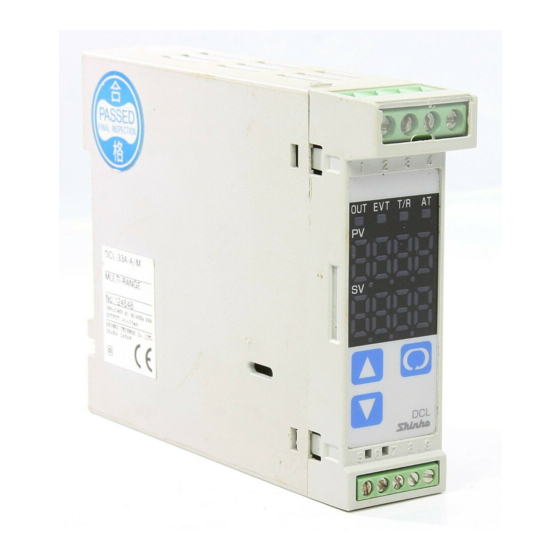
DIN rail mounting type indicating controller DCL-33A
3 A -
,
3
A
R
S
A
M
1
Model name label
DCL-33A-R/M
W(20A)
No.XXXXXXX
*Write 1 only for 24V AC/DC
for
Series name: DCL-300 (W22.5 x H75 x D100mm)
PID
Selectable by key operation *1
Relay contact: 1a
Non-contact voltage (for SSR): 12 , V DC
DC current: 4 to 20mA DC
Multi-range *2
Supply voltage 24V AC/DC *3
W (5A)
W (10A)
Heater burnout alarm
W (20A)
W (50A)
C5
Serial communication
(example)
Relay contact output/ Multi-range input
Heater burnout alarm output
CT input rating: 5A
CT input rating: 10A
CT input rating: 20A
CT input rating: 50A
Based on EIA RS-485
Advertisement
Table of Contents

Related Manuals for Shinko DCL-33A


Summary of Contents for Shinko DCL-33A
- Page 1 • Any unauthorized transfer or copying of this document, in part or in whole, is prohibited. • SHINKO TECHNOS CO., LTD is not liable for any damages or secondary damages incurred as a result of using this product, including any indirect damages.
-
Page 2: Mounting To The Control Panel
2. Name and functions of the sections (1) EVT indicator A red LED lights up when Event output [Alarm, Loop break alarm or Heater burnout alarm (Option)] is ON. (2) OUT indicator A green LED lights up when OUT output is ON. For current output type, this blinks in 0.25 seconds cycle corresponding to the output manipulated variable . - Page 3 [1] Hook (1) of the DCL-33A series on the upper side of the DIN rail. (Fig. 3.4-1) [2] Making (1) part of the DCL-33A series as a support, fit the lower part of the DCL-33A series to the DIN rail.
-
Page 4: Wiring And Connection
Shock causing severe injury or death. Caution • Do not leave wire chips into the DCL-33A series when wiring, because they could cause fire, malfunction and trouble. • Insert the connecting cable into the designated connector securely to prevent malfunction, or it may cause malfunction due to imperfect contact. - Page 5 • Option: Heater burnout alarm CT input socket This alarm is not available for detecting current under Power phase control. supply Use the current transformer (CT) provided, and pass a lead wire of the heater circuit into a hole of the CT. When wiring, keep the CT wire away from any AC source or load wires to avoid the external interference.
-
Page 6: Setting Flow Chart
5.1 Setting flow chart Output manipulated PV/SV display mode variable (Approx. 3s) (Approx. 3s) (Approx. 3s) (Approx. 3s) [Main setting mode] [Sub setting mode] [Auxiliary function [Auxiliary function 2 setting mode 1] setting mode 2] AT setting Setting value LOCK Sensor selection selection [ OUT proportional band setting... - Page 7 5.2 Main setting mode Character Name, Description, Setting range Default value • Sets the value for controlled object. • Scaling low limit value to scaling high limit value (Decimal point place follows the selection for DC voltage and current inputs) 5.3 Sub setting mode Character Name, Description, Setting range...
- Page 8 • Thermocouple and RTD inputs: -100.0 to 100.0 DC voltage and current inputs: -1000 to 1000 (Decimal point place follows the selection.) Communication protocol selection Shinko protocol • Selects communication protocol. • This item is not indicated when [Option: C5] is not added.
- Page 9 , Modbus ASCII mode: Modbus RTU mode: Instrument number setting • Sets individual instrument number to each DCL-33A when connecting plural DCL-33As in serial communication. • This item is not indicated when [Option: C5] is not added. • Setting range: 0 to 95...
- Page 10 (For DC voltage and current inputs, decimal point place follows the selection.) Decimal point place selection No decimal • Selects the decimal point place. point However, when thermocouple or RTD input is selected in the sensor selection, this setting item is not indicated. •...
- Page 11 Alarm action delayed timer setting 0 seconds • Sets the alarm action delayed time. Alarm output activates when the setting time has passed after the input enters alarm output range. • This setting item is not indicated when “No alarm” action is selected in [Alarm action selection].
-
Page 12: Converter Function
When mounting and wiring to the control panel (DIN rail) are finished, start the operation following the next procedure. (1) Turn the power supply to the DCL-33A series ON. For approx. 3s after power on, character of the sensor type and temperature unit are indicated on the PV display, and the input range high limit value is indicated on the SV display. - Page 13 (3) Turn the load circuit power ON. Starts control action so as to keep temperature of the controlled object at the main setting value.
-
Page 14: Action Explanations
8. Action explanations 8.1 OUT action Heating (Reverse) action Cooling (Direct) action Proportional band Proportional band Control action SV setting SV setting Relay contact output Cycle action is performed according to deviation Cycle action is performed according to deviation Non-contact 12V DC 0V DC 0/12V DC... - Page 15 8.3 Event (Alarm) action High limit alarm Low limit alarm High/Low limits alarm Alarm hysteresis Alarm hysteresis Alarm hysteresis Alarm action - Alarm setting + Alarm setting - Alarm setting Main + Alarm setting Main Alarm setting Main Alarm setting point point point...
- Page 16 9. PID auto-tuning of the DCL-33A Series In order to decide each P, I, D and ARW a value automatically, this system gives a fluctuation to the controlled object to get an optimal value. 1 of 3 types of fluctuation below are automatically selected.
- Page 17 10. Specifications 10.1 Standard specification Model name : DIN rail mounting indicating controller Mounting method : DIN rail mounting method Setting system : Input system using membrane sheet key Display : PV display: Red LED 4 digits, Character size 7.4 x 4mm (H x W) SV display: Green LED 4 digits, Character size 7.4 x 4mm (H x W) Input Thermocouple : K, J, R, S, E, T, N, PL- , C (W/Re5-26) External resistance: 100...
- Page 18 EVT output • Alarm output [Common output with Loop break alarm, Heater burnout alarm (option)] The alarm action point is set by deviation to the main setting (excluding Process alarm) and when input exceeds the range in deviation setting (excluding Process alarm) to the main setting, alarm (EVT) turns ON or OFF (High/Low limit range alarm), and when Deenergized is selected in Energized/Deenergized selection, alarm (EVT) is activated conversely.
- Page 19 Material : Flame resistant resin (Case) Color : Light gray (Case) Attached function: [Setting value lock] [Sensor correction] [Power failure countermeasure] The setting data is backed up in non-volatile IC memory. [Self-diagnosis] The CPU is monitored by a watchdog timer and when any abnormal status is found on the CPU, all outputs are OFF and controller is switched to warm-up status.
- Page 20 (with option SVTC) and the JCS-33A (with option C5) [Setting value LOCK of the DCL-33A must be set to LOCK 3.] When data from programmable controller is greater than SV high limit setting or smaller than SV low limit setting, DCL-33A ignores the value and controls the previous value that exceeded SV high limit or low limit.
-
Page 21: Troubleshooting
Set the proper value. even if the is pressed. • If you have any inquiries, please consult our agency or the shop where you purchased the unit. SHINKO TECHNOS CO.,LTD. OVERSEAS DIVISION 2-48, 1-Chome, Ina, Minoo, Osaka, Japan Reg. Office P.O.Box 17, Minoo, Osaka, Japan...
Need help?
Do you have a question about the DCL-33A and is the answer not in the manual?
Questions and answers