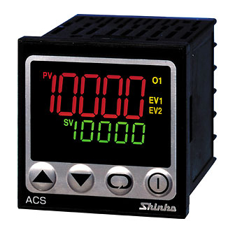
Shinko ACS-13A Instruction Manual
Digital indicating controller
Hide thumbs
Also See for ACS-13A:
- Instruction manual (44 pages) ,
- Communication instruction manual (16 pages) ,
- Communication instruction manual (1 page)
Table of Contents
Advertisement
Quick Links
INSTRUCTION MANUAL
For detailed usage and options, refer to the full Instruction manual for the ACS-13A.
Please download the full Instruction manual for the ACS-13A at http://www.shinko-technos.co.jp/e/
Thank you for purchasing our digital indicating controller ACS-13A.
This manual contains instructions for the mounting, functions, operations and notes when operating the
ACS-13A. To prevent accidents arising from the misuse of this controller, please ensure the operator receives
this manual.
Safety precautions
The safety precautions are classified into categories: "Warning" and "Caution".
Warning
: Procedures which may lead to dangerous conditions and cause death or serious injury, if not
carried out properly.
Caution
: Procedures which may lead to dangerous conditions and cause superficial to medium injury or
physical damage or may degrade or damage the product, if not carried out properly.
Warning
• To prevent an electric shock or fire, only Shinko or other qualified service personnel may handle the inner assembly.
To prevent an electric shock, fire or damage to the instrument, parts replacement may only be undertaken
•
by Shinko or other qualified service personnel.
Safety precautions
• To ensure safe and correct use, thoroughly read and understand this manual before using this instrument.
• This instrument is intended to be used for industrial machinery, machine tools and measuring equipment. Verify
correct usage after consulting the purpose of use with our agency or main office. (Never use this instrument for
medical purposes with which human lives are involved.)
• External protection devices such as protection equipment against excessive temperature rise, etc. must be
installed, as malfunction of this product could result in serious damage to the system or injury to personnel. Also
proper periodic maintenance is required.
• This instrument must be used under the conditions and environment described in this manual. Shinko Technos
Co., Ltd. does not accept liability for any injury, loss of life or damage occurring due to the instrument being
used under conditions not otherwise stated in this manual.
Caution with respect to Export Trade Control Ordinance
To avoid this instrument from being used as a component in, or as being utilized in the manufacture of weapons of
mass destruction (i.e. military applications, military equipment, etc.), please investigate the end users and the final
use of this instrument. In the case of resale, ensure that this instrument is not illegally exported.
1. Model
ACS – 1 3
Control action
A1
Control output
(OUT1)
Input
Supply voltage
Option
(Multiple options are selectable.)
*1: Alarm types (9 types and No alarm action) and Energized/De-energized can be selected by keypad.
*2: Thermocouple, RTD, DC current and DC voltage can be selected by keypad.
For DC current input, connect 50
*3: Supply voltage 100 to 240V AC is standard. When ordering 24V AC/DC, enter "1" after the input code.
Digital Indicating Controller
(Be sure to read these precautions before using our products.)
,
3
A
R
S
A
M
1
A2
W(20A)
W(50A)
W3(20A)
W3(50A)
DR
DS
C5
SM
shunt resistor (sold separately) externally.
ACS-13A
Series name: ACS-13A (W48 x H48 x D62mm)
PID
Alarm type can be selected by keypad. *1
Relay contact: 1a
Non-contact voltage (for SSR drive): 12V DC 15%
DC current: 4 to 20mA DC
Multi-range
*2
100 to 240V AC (standard)
24V AC/DC
*3
Alarm 2 output (A2) *1
CT rated current: 20A (Single-phase)
Heater
CT rated current: 50A (Single-phase)
burnout
CT rated current: 20A (3-phase)
alarm
CT rated current: 50A (3-phase)
control,
Heating/Cooling
Control output (OUT2)
Serial communication (RS-485)
Set value memory external selection
1
No.ACS11JE11 2013.02
Relay contact: 1a
Non-contact voltage: 12V DC 15%
Advertisement
Table of Contents

Related Manuals for Shinko ACS-13A


Summary of Contents for Shinko ACS-13A
- Page 1 Warning • To prevent an electric shock or fire, only Shinko or other qualified service personnel may handle the inner assembly. To prevent an electric shock, fire or damage to the instrument, parts replacement may only be undertaken •...
- Page 2 (32 to 122 ), Humidity: 35 to 85%RH (No icing and condensation) If the ACS-13A is installed through a control panel, the ambient temperature of the ACS-13A must be kept to under 50 . Otherwise the life of electronic parts (especially electrolytic capacitors) of the ACS-13A will be shortened.
- Page 3 (Fig. 3.3-1) +0.5 3.4 Mounting and removal to/from the control panel 3.4.1 How to mount the ACS-13A Mount the controller vertically to the flat, rigid panel to ensure it adheres to the Drip-proof/Dust-proof specification (IP66). Mountable panel thickness: 1 to 5mm (1) Insert the controller from the front side of the panel.
- Page 4 4.1 Terminal arrangement • EV1 : Alarm 1 output • EV2 : Alarm 2 output (A2 option) or Heater burnout alarm output (W, W3 option) • O2 : Control output (OUT2) (D option) • O1 : Control output (OUT1) : DC current, DC voltage input (For DC •...
- Page 5 0.0 to 10.0 times OUT1 -100.0 to 100.0 Scaling high limit proportional band -1000 to 1000 (DC input) Integral time Communication protocol : Shinko protocol 0 to 1000 sec : Modbus ASCII : Modbus RTU Approx. 3 sec Output MV indication Derivative time...
- Page 6 Characters used in this manual: Indication Number, Indication Alphabet Indication Alphabet (Table 5-1) Input type selection: [ ] (Default: K, -200 to 1370 ) -200 to 1370 -320 to 2500 -200.0 to 400.0 -320.0 to 750.0 -200 to 1000 -320 to 1800 0 to 1760 0 to 3200 0 to 1760...
- Page 7 PV display indicates setting item characters, and SV display indicates default value. Setting items with dotted lines are optional and they appear when the options are added. Key operation (Use the key to set or select each setting item.) • If the key is held down for 3 sec in any setting mode, the unit will revert to the PV/SV display mode.
- Page 8 Alarm type, Direct/Reverse control, etc. in the Setup mode. If the users’ specification is the same as the default value of the ACS-13A, it is not necessary to set up the controller. Proceed to Step (3). (3) Input each set value. Input each set value. Refer to “5. Operation flowchart” and “7.Basic settings”.
Need help?
Do you have a question about the ACS-13A and is the answer not in the manual?
Questions and answers