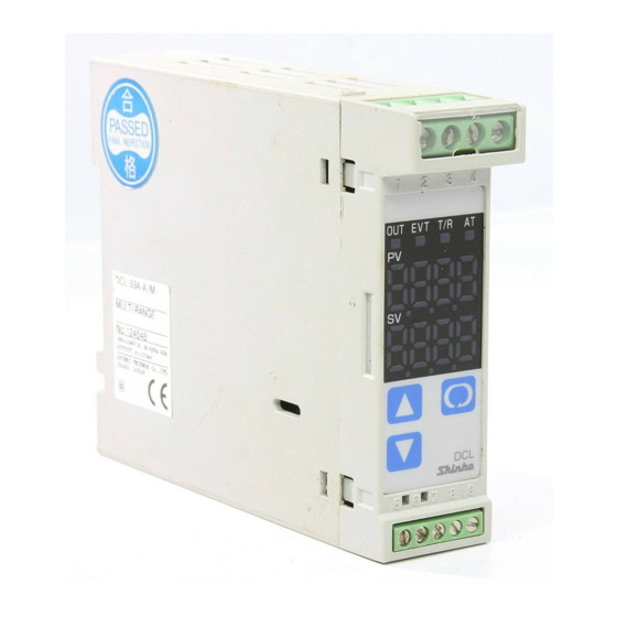
Shinko DCL-33A Instruction Manual
Din rail mounted indicating controller
Hide thumbs
Also See for DCL-33A:
- Instruction manual (56 pages) ,
- Communication instruction manual (40 pages) ,
- Instructions manual (21 pages)
Table of Contents
Advertisement
Quick Links
Download this manual
See also:
Instruction Manual
INSTRUCTION MANUAL
SHINKO TECHNOS CO., LTD.
Head office: 2-5-1, Senbahigashi, Minoo, Osaka, 562-0035, Japan
TEL: +81-72-727-6100
FAX: +81-72-727-7006
For detailed usage, refer to the Instruction Manual for the DCL-33A. Please download the full Instruction Manual from Shinko website.
http://shinko-technos.co.jp/e/
Support & Downloads
Downloads
Thank you for purchasing our DCL-33A, DIN Rail Mounted Indicating Controller. This manual contains instructions for the mounting, functions, operations and notes when
operating the DCL-33A. To ensure safe and correct use, thoroughly read and understand this manual before using this instrument. To prevent accidents arising from the
misuse of this instrument, please ensure the operator receives this manual.
Safety Precautions
(Be sure to read these precautions before using our products.)
The safety precautions are classified into 2 categories: "Warning" and "Caution".
Warning: Procedures which may lead to dangerous conditions and cause death or serious injury, if not
carried out properly.
Caution: Procedures which may lead to dangerous conditions and cause superficial to medium injury or
physical damage or may degrade or damage the product, if not carried out properly.
Warning
• To prevent electric shock or fire, only Shinko or other qualified service personnel may handle the inner
assembly.
• To prevent electric shock, fire or damage to the instrument, parts replacement may only be undertaken by
Shinko or other qualified service personnel.
SAFETY PRECAUTIONS
• To ensure safe and correct use, thoroughly read and understand this manual before using this instrument.
• This instrument is intended to be used for industrial machinery, machine tools and measuring equipment.
Verify correct usage after purpose-of-use consultation with our agency or main office. (Never use this
instrument for medical purposes with which human lives are involved.)
• External protection devices such as protective equipment against excessive temperature rise, etc. must be
installed, as malfunction of this product could result in serious damage to the system or injury to personnel.
Proper periodic maintenance is also required.
• This instrument must be used under the conditions and environment described in this manual. Shinko
Technos Co., Ltd. does not accept liability for any injury, loss of life or damage occurring due to the
instrument being used under conditions not otherwise stated in this manual.
Specifications
Power supply
100 to 240 V AC 50/60 Hz, Allowable voltage fluctuation: 85 to 264 V AC
voltage
24 V AC/DC 50/60 Hz, Allowable voltage fluctuation: 20 to 28 V AC/DC
Thermocouple input: Within
0.2% of each input span 1 digit, or 2
(4 ), whichever is greater
However, R, S inputs, 0 to 200
(0 to 400 ): Within
B input, 0 to 300
(0 to 600 ): Accuracy is not guaranteed.
Basic accuracy
K, J, E, T, N inputs, Less than 0
(32 ):
(at ambient
temperature 23 ,
Within
0.4% of input span 1 digit, or 4
(8 ), whichever is
for a single unit
greater
mounting)
RTD input: Within
0.1% of each input span 1 digit or
whichever is greater
DC voltage input: Within
0.2% of each input span 1 digit
Direct current input: Within
0.2% of each input span 1 digit
Input sampling
125 ms
period
100 to 240 V AC: Approx. 5 VA max.
Power
24 V AC: Approx. 4 VA max.
consumption
24 V DC: Approx. 4 W max.
Ambient
0 to 50 ,
Temperature,
35 to 85 %RH (Non-condensing)
Humidity
Weight
Approx. 100 g
Instruction manual excerpt: 1 copy
When W option is ordered: Connector harness 3 m 1 length
When W option (5A, 10A, 20A) is ordered: CT (CTL-6S) 1 piece
Accessories
When W option (50A) is ordered: CT (CTL-12-S36-10L1U) 1 piece
When EI option is ordered: Connector harness AOJ 3 m 1 length
When EA option is ordered: Connector harness AOJ 3 m 1 length
Relay contact 1a, Control capacity: 3 A 250 V AC (resistive load)
1 A 250 V AC (inductive load cos =0.4)
Electrical life: 100,000 cycles
Control output
Non-contact voltage (for SSR drive): 12 V DC 15%
(OUT1)
Max 40 mA (short circuit protected)
Direct current: 4 to 20 mA DC, Load resistance: Max 550
Output accuracy: Within
0.3% of output span
Resolution: 12000
和文は裏面をご覧下さい。
DIN Rail Mounted Indicating Controller
URL: http://www.shinko-technos.co.jp/e/
E-mail: overseas@shinko-technos.co.jp
Manuals
Caution for Installation
This instrument is intended to be used under the following environmental
conditions (IEC61010-1)]: Overvoltage category
Ensure the mounting location corresponds to the following conditions:
• A minimum of dust, and an absence of corrosive gases
• No flammable, explosive gases
• No mechanical vibrations or shocks
• No exposure to direct sunlight, an ambient temperature of 0 to 50
122 ) that does not change rapidly, and no icing.
• An ambient non-condensing humidity of 35 to 85 %RH
• No large capacity electromagnetic switches or cables through which large
current is flowing
• No water, oil or chemicals or where the vapors of these substances can
come into direct contact with the unit
• Take note that the ambient temperature of this unit – not the ambient
temperature of the control panel – must not exceed 50
through the face of a control panel, otherwise the life of electronic
components (especially electrolytic capacitors) may be shortened.
Caution with respect to Export Trade Control Ordinance
To avoid this instrument from being used as a component in, or as being
utilized in the manufacture of weapons of mass destruction (i.e. military
applications, military equipment, etc.), please investigate the end users and
the final use of this instrument. In the case of resale, ensure that this
instrument is not illegally exported.
Alarm output:
(Alarm, Loop break alarm and optional Heater burnout alarm utilize common
output terminals.)
The alarm action point is set by
deviation from the SV (excluding Process
6
(12 )
alarm), and if the input goes outside the range, alarm is turned ON or OFF
(High/ Low limit range alarm).
When De-energized action is selected in [Alarm action Energized/
De-energized], alarm is activated conversely.
Setting accuracy: Same as basic accuracy
1
(2 ),
Action: ON/OFF action
Hysteresis: Thermocouple, RTD inputs: 0.1 to 100.0
DC voltage, current inputs: 1 to 1000 (The placement of the
decimal point follows the selection.)
Output: Open collector, Control capacity: 0.1 A 24 V DC
Alarm Type: High limit alarm, Low limit alarm, High/Low limits alarm,
High/Low limits independent alarm, High/Low limit range alarm, High/Low
limit range independent alarm, Process high alarm, Process low alarm,
High limit with standby alarm, Low limit with standby alarm, High/Low
limits with standby alarm, High/Low limits with standby independent
alarm.
Energized/De-energized action are applied to the above alarms, totaling
EVT output
24 alarm types. No alarm action can also be selected.
Alarm Energized/De-energized: Alarm output Energized/ De-energized can
be selected.
Alarm Energized
EVT indicator (Red)
Lit
EVT output
ON
Alarm HOLD function: Once an alarm is activated, the alarm output is
maintained until the power is turned off.
Loop break alarm output:
(Loop break alarm, Alarm and optional Heater burnout alarm utilize common
output terminals.)
Detects heater burnout, sensor burnout and actuator trouble.
Setting range:
Loop break alarm time: 0 to 200 minutes
Loop break alarm span:
Thermocouple, RTD inputs: 0 to 150
DC voltage, current inputs: 0 to 1500 (The placement of the decimal point
follows the selection.)
Output: Open collector, Control capacity: 0.1 A 24 V DC
Heating/Cooling
control output
Output: Open collector, Control capacity: 0.1 A 24 V DC
(OUT2)
(DC option)
DCL-33A
External Dimensions
No. DCL31JE1 2016.06
, Pollution degree 2
(32 to
Name and Functions
(122 ) if mounted
Caution
When setting the specifications and functions of this unit, connect mains power cable to terminals 1 and 2 first, then set them referring to "Key Operation Flowchart",
( )
before "Mounting to the Control Panel" and "Wiring".
Do not pull or bend the lead wire on the terminal side when wiring or after wiring, as it could cause malfunction.
Terminal Arrangement
Alarm De-energized
Lit
OFF
( ) or 0.0 to 150.0
( )
When using ferrules, use the following ferrules made by Phoenix Contact GMBH & CO.
Recommended Ferrules and Crimping Pliers
Terminal
Terminal
Ferrules with
Number
Screw
Insulation Sleeve
AI 0.25-8 YE
AI 0.34-8 TQ
AI 0.5-8 WH
1 to 4
M2.6
AI 0.75-8 GY
AI 1.0-8 RD
AI 1.5-8 BK
AI 0.25-8 YE
5 to 9
M2.0
AI 0.34-8 TQ
AI 0.5-8 WH
(Scale: mm)
DIN rail
No.
Name
The red LED turns on when Event output (Alarm, Loop break alarm or optional Heater burnout alarm) is ON.
①
EVT indicator
The red LED also turns on when Cooling output is ON if Heating/Cooling control option is ordered.
The green LED turns on when OUT (control output) is ON (when Heating output is ON if Heating/Cooling control option is
ordered).
OUT indicator
②
For Direct current output, flashes in 125 ms cycles corresponding to the output MV.
③
T/R indicator
The yellow LED flashes during Serial communication TX output (transmitting).
④
AT indicator
The yellow LED flashes while auto-tuning (AT) is performing.
PV Display
⑤
Indicates the PV (process variable), or setting characters in setting mode with a red LED.
SV Display
⑥
Indicates the SV (desired value), output MV (manipulated variable) or each set value in each setting mode with a green LED.
UP key
Increases the numeric value.
⑦
⑧
DOWN key
Decreases the numeric value.
Switches the setting mode or registers the set data.
⑨
MODE key
(Registers the set data by pressing the MODE Key.)
Enters Auxiliary function setting mode 2 in combination with the MODE key.
If Control output OFF is selected in [SUB-MODE key function]: Turns all outputs OFF as if the power were turned OFF.
⑩
SUB-MODE key
If Auto/Manual control is selected in [SUB-MODE key function]: Switches the Auto/Manual control.
If Alarm HOLD cancel is selected in [SUB-MODE key function]: Cancels Alarm HOLD.
Name
PWR
100 to 240 V AC or 24 V AC/DC
(POWER SUPPLY)
For 24 V DC, ensure polarity is correct.
O1
Control output (OUT1)
Bottom of the unit
TC
Thermocouple
RTD
Resistance temperature detector
Direct current or DC voltage
DC
Commu-
For Direct current input, connect a shunt resistor (50
nication
Event output
EV
C5
Outputs when Alarm, Loop break alarm or Heater burnout alarm (W option) is ON.
(RS-485)
O2
Cooling output (DC option)
RS-485
Serial communication (C5 option)
CT
Current transformer input (W option)
CT
EA
External setting input (EA option)
EA
EI
EI
DI1 input (EI option)
Conductor Cross
Tightening Torque
Crimping Pliers
Sections
0.2 to 0.25 mm
2
0.25 to 0.34 mm
2
0.34 to 0.5 mm
2
0.5 to 0.6 N・m
0.5 to 0.75 mm
2
CRIMPFOX ZA 3
2
0.75 to 1.0 mm
CRIMPFOX UD 6
1.0 to 1.5 mm
2
0.2 to 0.25 mm
2
0.25 to 0.34 mm
2
0.22 to 0.25 N・m
0.34 to 0.5 mm
2
Description
Description
) between input terminals.
Advertisement
Table of Contents

Related Manuals for Shinko DCL-33A


Summary of Contents for Shinko DCL-33A
- Page 1 Thank you for purchasing our DCL-33A, DIN Rail Mounted Indicating Controller. This manual contains instructions for the mounting, functions, operations and notes when operating the DCL-33A. To ensure safe and correct use, thoroughly read and understand this manual before using this instrument. To prevent accidents arising from the misuse of this instrument, please ensure the operator receives this manual.
- Page 2 SV start H/L limit range The alarm action is deviation setting from the SV. Operation before RUN DCL-33A ON. Set value lock No event Low limit alarm The alarm is activated if the input value goes under -199.9 - 400.0°C PV start JPt100 -199.9 - 900.0°F...
Need help?
Do you have a question about the DCL-33A and is the answer not in the manual?
Questions and answers