Table of Contents
Advertisement
OGRANICZNIKI I BEZPIECZNIKI TEMPERATURY BCD2R, T7672
To prevent accidents arising from the misuse of this controller, please ensure the operator receives this manual
Safety precautions
The safety precautions are classified into categories: "Warning" and "Caution". Depending on circumstances,
procedures indicated by
for usage.
Procedures which may lead to dangerous conditions and cause death or serious
Warning
injury, if not carried out properly.
Procedures which may lead to dangerous conditions and cause superficial to medium
Caution
injury or physical damage or may degrade or damage the product, if not carried out
properly.
Warning
• To prevent an electric shock or fire, only our or other qualified service personnel may handle the inner
assembly.
• To prevent an electric shock, fire or damage to the instrument, parts replacement may only be undertaken
by our or other qualified service personnel.
Safety precautions
• To ensure safe and correct use, thoroughly read and understand this manual before using this instrument.
• This instrument is intended to be used for industrial machinery, machine tools and measuring equipment. Verify
correct usage after purpose-of-use consultation with our agency or main office. (Never use this instrument for
medical purposes with which human lives are involved.)
• External protection devices such as protection equipment against excessive temperature rise, etc. must be
installed, as malfunction of this product could result in serious damage to the system or injury to personnel.
Proper periodic maintenance is also required.
• This instrument must be used under the conditions and environment described in this manual. Shinko Technos
Co., Ltd. does not accept liability for any injury, loss of life or damage occurring due to the instrument being used
under conditions not otherwise stated in this manual.
Caution with respect to Export Trade Control Ordinance
To avoid this instrument from being used as a component in, or as being utilized in the manufacture of weapons of
mass destruction (i.e. military applications, military equipment, etc.), please investigate the end users and the final
use of this instrument. In the case of resale, ensure that this instrument is not illegally exported.
Caution
• This instrument should be used according to the specifications described in the manual.
If it is not used according to the specifications, it may malfunction or cause a fire.
• Be sure to follow the warnings, cautions and notices. If they are not observed, serious injury or malfunction
may occur.
• Specifications of the BCD2 and the contents of this instruction manual are subject to change without notice.
• Measures must be taken to ensure that the operator cannot touch power terminals or other high voltage
sections.
• Be sure to turn the power supply to the instrument OFF before cleaning this instrument.
• Use a soft, dry cloth when cleaning the instrument.
(Alcohol based substances may tarnish or deface the unit.)
• As the display section is vulnerable, do not strike or scratch it with a hard object.
• Any unauthorized transfer or copying of this document, in part or in whole, is prohibited.
•
Shinko Technos Co., Ltd. is not
this product, including any indirect damages.
(Be sure to read these precautions before using our products.)
Caution may result in serious consequences, so be sure to follow the directions
liable for any damages or secondary damages incurred as a result of using
1
BCD2R,T7672
BCD23T7672E1 2016.02
.
Advertisement
Table of Contents

Related Manuals for Shinko BCD2R


Summary of Contents for Shinko BCD2R
- Page 1 Proper periodic maintenance is also required. • This instrument must be used under the conditions and environment described in this manual. Shinko Technos Co., Ltd. does not accept liability for any injury, loss of life or damage occurring due to the instrument being used under conditions not otherwise stated in this manual.
- Page 2 1. Model 1.1 Model BCD2 OUT1 Limit control output (Relay contact: 1a) Power supply 100 to 240 V AC (Standard) voltage 24 V AC/DC Input Multi-range (*1) No option 1 needed. A2 output ( (*2) Alarm type can be selected by keypad) Option No option 2 needed.
-
Page 3: Name And Functions Of The Sections
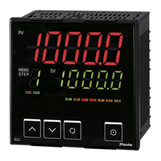
2. Name and functions of the sections (12) (5) (6) (10) (11) (Fig. 2-1) (1) PV Display Indicates the PV (process variable) with a red LED. Indicates setting item characters during the setting mode. (2) SV Display Indicates the SV (desired value) with a green LED. Indicates set (selected) value during the setting mode. -
Page 4: Mounting To The Control Panel
3. Mounting to the control panel 3.1 Site selection Caution • Use within the following temperature and humidity ranges. Temperature: -10 to 55 (14 to 131 ), Humidity: 35 to 85 %RH (No condensation, no icing) • When this unit is installed through the control panel, the ambient temperature of this unit – not the ambient temperature of the control panel –... - Page 5 Caution As the case is made of resin, do not use excessive force while screwing in the mounting bracket, or the case or screw type mounting bracket could be damaged. The torque is approximately 0.1 N•m. 3.4 Mounting Mount the controller vertically to the flat, rigid panel to ensure it adheres to the Drip-proof/Dust-proof specification (IP66).
- Page 6 4. Wiring Warning Turn the power supply to the instrument off before wiring or checking. Working on or touching the terminal with the power switched on may result in severe injury or death due to electrical shock. • TRANSMIT OUTPUT: Transmission output •...
- Page 7 5. Settings 5.1 Operation flowchart Outline of operation procedure Set Input type, Alarm (type, value, etc.) and SV (desired value), following the procedures below. Setting item numbers (1) to (7) are indicated on the flowchart. [Step 1 Operation before run] Turn the load circuit power OFF, and turn the power supply to the BCD2 ON. [Step 2 Setup mode] Set Input type, Alarm type, etc.
- Page 8 Input type (character indication) and range Alarm type -200 to 1370 -320 to 2500 (High limit alarm): The alarm action is deviation setting from the SV. The alarm is -199.9 to 400.0 -199.9 to 750.0 activated if the PV (process variable) reaches the high limit set value. -200 to 1000 -320 to 1800 (Low limit alarm):...
- Page 9 After the power is turned on, the sensor input characters and temperature unit are indicated in the PV Display, and the input range high limit value is indicated in the SV Display for approximately 3 seconds. See (Table 5-1). (If any other value is set in [Scaling high limit], the value is indicated in the SV Display) During this time, all outputs and the LED indicators are in OFF status.
-
Page 10: Setting Range
5.3 Main setting mode Sets SV, A1 and A2 value. To enter Main setting mode, press the keys (in that order) together in PV/SV Display Mode. Use the key for settings (or selections). To register the set data, use the key.. - Page 11 : 9600 bps : 19200 bps Parity Even parity • Selects the parity. • Not available if the C5 option is not ordered or if Shinko protocol is selected in [Communication protocol]. • Selection: : No parity : Even parity...
- Page 12 5.5 Setup mode Sets an input type, A1, A2 type, High/Low limit control, etc. To enter Setup mode, press and hold the keys (in that order) together for 3 seconds in PV/SV Display Mode. Use the key for settings (or selections). To register the set data, use the key.
- Page 13 Character Name, Function, Setting range Default value A1 type No alarm action • Selects an action type for A1. • Selection range: : No alarm action High limit alarm Low limit alarm High/Low limits alarm High/Low limit range alarm Process high alarm Process low alarm High limit alarm with standby Low limit alarm with standby...
-
Page 14: Sensor Correction Function
Character Name, Function, Setting range Default value Auto/Manual limit control Auto limit control • Selects either auto or manual limit control action. (Refer to Section 7.3) • Selection item: : Auto limit control : Manual limit control Hour:Minute EXC indicator lighting duration time unit •... -
Page 15: Action Explanation
7. Action explanation 7.1 High limit control action (Fig. 7.1-1) Auto limit control will be used for purposes of explanation of the High limit control action. (Refer to Section 7.3) key or External reset input OUT1 hysteresis Energized action Unlit Unlit EXCEEDED indicator Unlit... - Page 16 7.2 Low limit control action (Fig. 7.2-1) Auto limit control will be used for purposes of explanation of the Low limit control action. (Refer to Section 7.3) key or External reset input De-energized action (Fig. 7.2-1) (1) Limit control action will initiate after power supply to the controller is turned on. (2) If PV drops below SV, the EXCEEDED and RESET indicators light, and OUT1 (Limit control output terminals 15 and 16) is turned OFF.
- Page 17 7.4 A1, A2 action High limit alarm Low limit alarm High/Low limits alarm A1 hysteresis A1 hysteresis A1 hysteresis A1 action A1 set point A1 set point A1 set point A1 set point + A1 set point + A1 set point + side + side A1 output...
-
Page 18: Specifications
8. Specifications 8.1 Standard specifications Mounting: Flush Setting: Input system using membrane sheet key Display PV Display: Red LED 4 digits, character size 24 x 11 mm (H x W) SV Display: Green LED 4 digits, character size 14 x 7 mm (H x W) Accuracy (Setting and Indication): Thermocouple: Within 0.2% of each input span... - Page 19 External reset input function By connecting External reset input terminals 9 and 12 (while the RESET indicator is lit), the RESET indicator goes off, OUT1 (Limit control output terminals 15 and 16) is turned ON, and limit control action initiates. However, while the EXCEEDED indicator is lit, limit control action does not initiate even though External reset input terminals 9 and 12 are shorted.
- Page 20 Attached functions: [Set value lock] [Sensor correction] [Auto/Manual limit control] [Input error indication]: Thermocouple, RTD input: If measured value exceeds Indication range high limit value, the PV Display flashes “ ”. If measured value drops below Indication range low limit value, the PV Display flashes “ ”.
- Page 21 [Automatic cold junction temperature compensation] (Only thermocouple input type) This detects the temperature at the connecting terminal between the thermocouple and the instrument, and always maintains at the same status as if the reference junction location temperature was at 0 (32 ).
- Page 22 Parity: Even, Odd and No parity (Selectable by keypad) (Default: Even parity) Stop bit: 1, 2 (Selectable by keypad) (Default: 1) Communication protocol: Shinko protocol, Modbus ASCII, Modbus RTU (Selectable by keypad) Data format: Shinko protocol Modbus ASCII Modbus RTU...
-
Page 23: Troubleshooting
9. Troubleshooting If any malfunctions occur, refer to the following items after checking the power supply to the controller. 9.1 Indication Problem Presumed cause and solution • The controller is in the EXCEEDED indicator lighting duration time “ ” is indicated in the PV mode. - Page 24 • Check whether the wiring of sensor or control output terminals is correct. • For all other malfunctions, please contact our main office or dealers. SHINKO TECHNOS CO., LTD. OVERSEAS DIVISION Head Office 2-5-1, Senbahigashi, Minoo, Osaka, Japan http://www.shinko-technos.co.jp...
Need help?
Do you have a question about the BCD2R and is the answer not in the manual?
Questions and answers