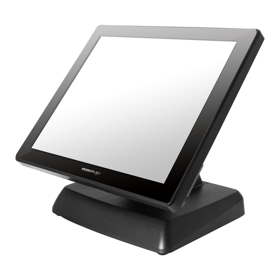
POSIFLEX XT-6317 User Manual

POSIFLEX XT-6317 User Manual

Fanless pos terminal

Advertisement

XT-6317/6517
Fanless POS Terminal
User Manual
Product Features
Fanless Design
Intel Kaby Lake platform
New Gen 7E foldable base that allows JIVA XT Series to be configured
into different configurations
New Gen 8E foldable base that integrates internal power adaptor and
Powered USB port into the base
M.2 expansion slots for SSD storage and Wi-Fi / Bluetooth
communication module
16800901010 Ver. A0
http://www.posiflex.com
Package Contents
17" P-CAP touch terminal with Gen 7E or
Gen 8E base................................(x1)
Power adapter..............................(x1)
Power cord.................................(x1)
User manual................................(x1)
1

Advertisement

Table of Contents
loading
Need help?

Need help?

Do you have a question about the XT-6317 and is the answer not in the manual?

Questions and answers

Subscribe to Our Youtube Channel

Summary of Contents for POSIFLEX XT-6317

  • Page 1 XT-6317/6517 Fanless POS Terminal User Manual Package Contents  17” P-CAP touch terminal with Gen 7E or Gen 8E base…………………………..(x1)  Power adapter………………………...(x1)  Power cord……………………………(x1)  User manual…………………………..(x1) Product Features  Fanless Design  Intel Kaby Lake platform ...
  • Page 2 SOME IMPORTANT NOTES FCC NOTES This system meets industry & government requirements and applicable standards. This equipment generates, uses, and can radiate radio frequency energy and, if not installed and used in accordance with the instructions manual, may cause interference to radio communications. It has been tested and found to comply with limits for a Class A digital device pursuant to subpart B of Part 15 of FCC Rules, which are designed to provide reasonable protection against interference when operated in a commercial environment.
  • Page 3: Consignes De Sécurité

    CONSIGNES DE SÉ CURITÉ Cet équipement ne convient pas à une utilisation dans des lieux pouvant accueillir des enfants. BATTERY CAUTION NOTES  Dispose of used batteries according to the instructions.  Replacement of a battery with an incorrect type that can defeat a safeguard (for example, in the case of some lithium battery types) ...
  • Page 4 Views of XT-6317/6517 with Gen 7E Base Front View P-CAP Touch Panel Gen 7E Base LED indicator Rear View HDD/SSD Cover Neck Cover Cable Cover Cable Exit Side View Power Button Brightness Adjustment Button + Brightness Adjustment Button -...
  • Page 5 Bottom View Rubber Feet with Fixing Screw Cable Exit Cable Holder Rubber Feet with Fixing Screw Views of XT-6317/6517 with Gen 8E Base Front View P-CAP Touch Panel Gen 8E Base LED indicator Rear View HDD/SSD Cover Neck Cover Cable Cover...
  • Page 6 UPS Battery Compartment Power Adapter Compartment PoweredUSB HDD Compartment Compartment Rubber Feet with Fixing Screw View of I/O Interface of XT-6317/6517 12V BAT Port VGA Port (UPS Port) RJ-50 COM Ports USB 2.0 Ports HDMI Port USB 3.0 Ports LAN Ports...
  • Page 7 Positioning your POS for a Perfect Viewing Angle The adjustable bases designed for XT-6317/6517 come in two models, Gen 7E/8E, and allow you to determine an ideal position for your terminal by using its unique tilt adjustment mechanism. As the below figures suggest, both bases provide three standard positioning solutions for your terminal: Flat Folded mode, Low Profile mode, and Full Extended mode.
  • Page 8 In general, XT-6317/6517 will be set up beforehand in Flat Folded mode and then packaged into the box for shipping. After it is unpacked, you may re- adjust the terminal in either Low Profile mode or Full Extended mode according to your situation. Below will provide instructions on how to adjust the specific base connected to the POS system.
  • Page 9 Return your terminal back to Flat Folded mode from Full Extended mode. Tilt your screen in a horizontal position. Then, remove the cable cover from the base. Support the screen with one hand holding onto its bottom edge. While pulling the lever backwards, move the display downwards until the lever is lifted off the hook as shown in the figure Hook Lever...
  • Page 10 XT-6317/6517 with Gen 8E Base Please refer to the following instructions on how to switch among different positioning modes to find an ideal viewing angle for XT-6317/6517 with Gen 8E base. Unpack XT-6317/6517, which is supposed to be set in flat folded mode, out of the package box and then lay your POS system on a flat surface.
  • Page 11 Push the cable cover outwards to remove it from the base. Position your terminal in Full Extended mode. Support the screen with one hand holding onto its bottom edge. Then, while pulling the lever backwards, move the display upwards until the lever is snapped into the lower hook to raise the screen as shown in the below figure.
  • Page 12 Position the terminal in Low Profile mode. While keeping your terminal steady with your hand holding on to the base, tilt your terminal down. Then, remove the cable cover from the base. Support the screen with one hand holding onto its bottom edge. Then, while pulling the lever backwards, move the display upwards or downwards until the lever is snapped into the upper hook to lower the screen as shown in the below figure.
  • Page 13 Return the terminal back to Flat Folded mode. While steadying your terminal with your hand holding onto the base, tilt your screen up. Support the screen with one hand holding onto its bottom edge. While pulling the lever backwards, release the lever back to the point above the upper hook as shown in the figure.
  • Page 14 Connecting Power Adapter and I/O Cables To have the terminal ready for operation, please connect the connector of power adapter and all of the connectors of required I/O cables respectively to the 12VDC-IN power jack and appropriate I/O ports. Please make sure that each of the cables is fully connected to each of the correct ports.
  • Page 15 Remove the cable cover. Pull outwards the locking levers with your forefingers and then remove the neck cover in the direction shown by the arrow. Tilt the screen to the horizontal position. Thread the cables along the cable passage and then through the cable exit. Tilt the terminal up enough to have the bottom I/O plate towards you.
  • Page 16 Gen 8E base Installing Optional Upgrade Kits and Peripherals XT-6317/6517 is an expandable model which allows you to upgrade its own capacity by additionally installing multiple peripheral devices, such as magnetic stripe reader (MSR), LCD monitor, and cash drawer, according to your preference.
  • Page 17  Installing UPS Battery to Gen 8E Base UPS battery compartment can be found at the bottom of Gen 8E base as shown in the figure. Please be advised that the installation of UPS battery should be conducted by a technician according to the user manual specific to UPS battery.
  • Page 18 After pushing the power adapter up to the top, place two brackets separately on the top and bottom sides of the power adapter compartment as shown in the figure. Then, fasten two brackets with four fixing screws. Bracket Power Adaptor Before threading the cable through the cable exit, loosen two fixing screws for the bracket of the PoweredUSB compartment.
  • Page 19 Neatly thread the cord along the bottom edge of the PoweredUSB compartment (1), and then use the cable tie to hold the extra cable (2) as shown in the figure. Cable tie Place back the PoweredUSB compartment bracket into place, and then secure it using two fixing screws.
  • Page 20 Installing an Operating System You are highly advised not to install an operating system on XT-6317/6517 without professional instructions. Not only might the careless handling during installation cause irreversible damage to your machine, but also the improper installation likely leads to system malfunction or failure.
  • Page 21: Operation Environment

    Operation Environment To prevent XT-6317/6517 from overheating, it is suggested to position your terminal in a well-ventilated working environment. In doing so, please be advised to keep the POS terminal at least 25mm away from other devices to ensure the machine is properly cooled down and functioning normally.
  • Page 22: Specifications

    0°C - 40°C, 20%RH - 90%RH Condition Storage -20°C - 70°C, 10%RH - 90%RH ※ The product information and specifications are subject to change without prior notice. To get the detailed information on the XT-6317/6517, please check this model from Posiflex Global Website...
  • Page 23 <MEMO>...
  • Page 24 <MEMO>...

This manual is also suitable for:

Xt-6517

Table of Contents