Table of Contents
Advertisement
Quick Links
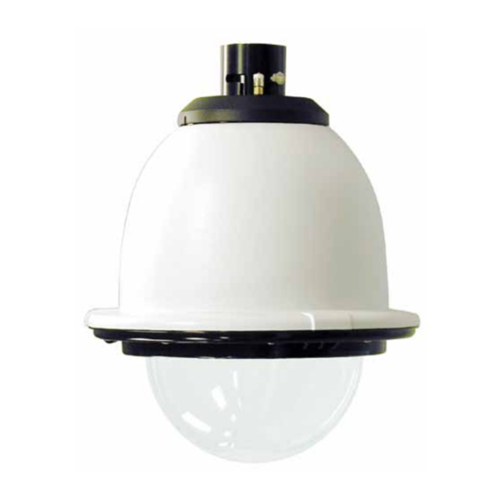
P F D W 7 5 C 2 N
Outdoor Pressurized Network Fusion Dome
Installation and Operation Instructions for the following models:
PFDW75C2N
IP Network Ready 7" Outdoor pressurized dome housing
with WM20G gooseneck wall mount, with 24VAC input,
heater/blower, for Network cameras, 120 to 24VAC, 96vA
transformer, clear dome
PFDW75T2N
IP Network Ready 7" Outdoor pressurized dome housing
with WM20G gooseneck wall mount, with 24VAC input,
heater/blower, for Network cameras, 120 to 24VAC, 96vA
transformer, tinted dome
Before attempting to connect or operate this product,
please read these instructions completely.
www.videolarm.com
CERTIFIED
81-IN5353
02-17-2011
Advertisement
Table of Contents

Subscribe to Our Youtube Channel
Related Manuals for Moog Videolarm PFDW75T2N


Summary of Contents for Moog Videolarm PFDW75T2N
- Page 1 P F D W 7 5 C 2 N Outdoor Pressurized Network Fusion Dome www.videolarm.com Installation and Operation Instructions for the following models: PFDW75C2N IP Network Ready 7” Outdoor pressurized dome housing with WM20G gooseneck wall mount, with 24VAC input, heater/blower, for Network cameras, 120 to 24VAC, 96vA transformer, clear dome PFDW75T2N IP Network Ready 7” Outdoor pressurized dome housing with WM20G gooseneck wall mount, with 24VAC input, CERTIFIED heater/blower, for Network cameras, 120 to 24VAC, 96vA transformer, tinted dome Before attempting to connect or operate this product, 81-IN5353 02-17-2011...
- Page 2 IMPORTANT SAFEGUARDS SAFETY PRECAUTIONS Read these instructions. Keep these instructions. CAUTION Heed all warnings RISK OF ELECTRIC SHOCK DO NOT OPEN Follow all instructions. Do not use this apparatus near water. CAUTION: TO REDUCE THE RISK OF Clean only with damp cloth. ELECTRIC SHOCK, DO NOT REMOVE Do not block any of the ventilation openings.
-
Page 3: Limited Warranty
LIMITED WARRANTY FOR VIDEOLARM INC. PRODUCTS VIDEOLARM INC. warrants this Product to be free from defects in material or workmanship,as follows: PRODUCTCATEGORY PARTS LABOR All Enclosuresand Electronics Five (5) Years Five (5) Years Pan/Tilts Three (3) Years **6 months if used in autoscan Three (3) Years **6 months if used in autoscan /tour operation /tour operation... -
Page 4: Electrical Specifications
Electrical Specifications Contents of Box Power 24VAC PFDW75C2N Class 2 Only 24 VAC 3.3 Amps Total Power: 80 Watts Accessories: Heater: 50 Watts/Blower: 2 Watts Camera Power: 28 Watts Max Tools Required: .100” Flat Head Screwdriver English Phillips Head Screwdriver 7/16”... - Page 5 Wrap Teflon tape around the pipe threads Securely mount bracket to wall. Pull wiring to ensure a tight seal. through bracket and position grommet as shown. • Con seguridad soporte del montaje a emparedar. Tire del cableado • La cinta del Teflon del abrigo alrededor de la pipa rosca a través del soporte y del ojal de la posición según lo demostrado.
- Page 6 Loop the lanyard over the set screw to Make the appropriate wiring connections temporarily hold housing. from the dome to the gooseneck. • Coloque el acollador sobre el tornillo de presión para • Haga las conexiones apropiadas del cableado de la bóveda celebrar temporalmente la cubierta.
- Page 7 RJ45 24VAC POWER Camera Yellow Max 80 Watts Camera Green Heater/Blower Yellow 26 Watts Heater/Blower Green Alarm 1 Blue Alarm 2 Violet Alarm 3 Gray Common White Make the appropriate male and female connections. Indoor model does not include pre-run cables. •...
- Page 8 Undo the lanyard, pull housing up and twist Slide the grommet down over the coupling to prevent secure with the locking bolt and washers. water from entering and complete the assembly. • Resbale el ojal abajo sobre el acoplador para evitar que el agua •...
- Page 9 Air Chuck Fitting Hose Air Chuck Regulator Tank Valve Nitrogen Tank Place the air chuck on the tank valve and When pressurizing unit be sure to set the begin filling until pressure relief valve opens. guage or regulator from 10-20psi (.7-1.4bar). •...
- Page 10 Axis 213 (3) #8x3/8” Captive Screw Mounting Plate 1" 2" MOUNTING HOLE MOUNTING HOLE Install the camera to the mounting plate with (2) #10 screws and lock washers provided. Place (3) #8x3/8” screws on the spacers and align the mounting slots. Slide on plate and camera then secure. •...
- Page 11 Axis 215 (3) #8x3/8” Mounting Plate ½" 1" 2" MOUNTING HOLE MOUNTING HOLE Install the camera to the mounting plate using (4) #8 bolts and star washers. Place (3) #8x3/8” screws on the spacers and line up the mounting slots. Slide plate in and secure. •...
-
Page 12: Connection Module
Connection Module Screw Power Board To remove the power board, use screwdriver to release plastic fasteners by applying pressure to sides while pulling out. This is what the typical path of illumination will look like with the setting at 30 degrees. Attach connection module as shown. - Page 13 Axis 233D Remove power board located inside of housing and then remove mounting bracket. • Quite a tablero de energía situado dentro de la cubierta y después quite el soporte de montaje. • Enlevez carte d'alimentation situé à l'intérieur de du logement et puis enlevez le support. •...
- Page 14 Acti 8201 Captive (4) #8x3/8” Screw Mounting Plate ½" 1" 2" MOUNTING HOLE Attach camera bracket to mounting plate using (1) ¼” x 20 bolt, washer and lock washer. Complete assembly as shown, securing camera and mounting plate to spacers. •...
- Page 15 CANON VB-C300 Captive (4) #8x3/8” Screw Mounting Plate ½" 1" 2" MOUNTING HOLE Attach camera to mounting plate using (1) ¼” x 20 bolt, lock washer, and washer. Complete assembly as shown, then secure camera to the quick release plate. •...
- Page 16 ICanView 250 Captive (3) #8x3/8” Screw Mounting Plate ½" 1" MOUNTING HOLE Position camera pins into slotted curved openings rotate to lock. Secure with set screw and nut • Los pernos de la cámara de la posición en aberturas curvadas ranuradas giran a la cerradura. Asegure con el tornillo de presión y la tuerca •...
-
Page 17: Jvc-Vn-C655U
JVC-VN-C655U Captive (3) #8x3/8” Screw Mounting Plate ½" 1" MOUNTING HOLE Attach camera to mounting plate using (4) #8 screws and star washer. Complete assembly as shown, then secure camera to the quick release plate. • Ate la cámara a la pletina usando (4) los tornillos #8 y arandela de la estrella. Termine a la asamblea como se muestra, entonces cámara segura a la placa del lanzamiento rápido. - Page 18 Panasonic WVNS202 Captive (3) #8x3/8” Screw Mounting Plate ½" 2" MOUNTING HOLE Attach camera to mounting plate using (4) #8 screws and star washer. Complete assembly as shown, then secure camera to the quick release plate. • Ate la cámara a la pletina usando (4) los tornillos #8 y arandela de la estrella. Termine a la asamblea como se muestra, entonces cámara segura a la placa del lanzamiento rápido.
- Page 19 Sony RX550 Captive (2) #8x3/8” Screw Mounting Plate No bolt used here MOUNTING HOLE Attach camera to mounting plate using (4) M3 bolts and lock washers. Complete assembly as shown, then secure camera to the quick release plate. • Ate la cámara a la pletina usando (4) los pernos M3 y las arandelas de cerradura. Termine a la asamblea como se muestra, entonces cámara segura a la placa del lanzamiento rápido.
- Page 20 Sony RZ30 Captive (3) #8x3/8” Screw Mounting Plate 2" MOUNTING HOLE Attach camera to mounting plate using (1) ¼” x 20 bolt, washer, and lock washer. Complete assembly as shown, then secure camera to the quick release plate. • Ate la cámara a la pletina usando (1) perno de x 20 del ¼”, arandela, y arandela de cerradura. Termine a la asamblea como se muestra, entonces cámara segura a la placa del lanzamiento rápido.
- Page 21 TOA 2564 Captive (4) #8x3/8” Screw Mounting Plate MOUNTING HOLE Attach camera to mounting plate using (4) #8 screws and star washer. Complete assembly as shown, then secure camera to the quick release plate. • Ate la cámara a la pletina usando (4) los tornillos #8 y arandela de la estrella. Termine a la asamblea como se muestra, entonces cámara segura a la placa del lanzamiento rápido.
- Page 22 Pixord 261/263 Captive (3) #8x3/8” Screw Mounting Plate 1" MOUNTING HOLE Attach camera quick release bracket to mounting plate using (3) 8 x 32 x ⅜” bolts, lock washers, and nuts. Complete assembly as shown. • Ate el soporte del lanzamiento rápido de la cámara a la pletina usando (3) pernos del ⅜ de 8 x 32 x los”, las arandelas de cerradura, y las tuercas. Termine a la asamblea como se muestra.
-
Page 24: Product Registration/Warranty
Product Registration/Warranty Thank you for choosing Videolarm. We value your patronage and are solely committed to providing you with only the highest quality products available with unmatched customer service levels that are second-to-none in the security industry. Should a problem arise, rest assure that Videolarm stands behind its products by offering some of the most impressive warranty plans available: 3 Years on all Housings, Poles, Power Supplies, and Accessories and 5 Years on all camera systems (SView, QView, Warriors), and InfraRed Illuminators.
Need help?
Do you have a question about the PFDW75T2N and is the answer not in the manual?
Questions and answers