Table of Contents
Advertisement
Quick Links
®
INSTALLATION, OPERATION
& MAINTENANCE MANUAL
MODEL:
HD2P-12000F
12,000 LB CAPACITY 2 POST LIFT
FOLLOW THIS MANUAL CAREFULLY TO ENSURE THE EQUIPMENT WILL
FUNCTION CORRECTLY AND PROVIDE MANY YEARS OF DEPENDABLE SERVICE.
FAILURE TO FOLLOW THESE INSTRUCTIONS AND SAFETY WARNINGS MAY
RESULT IN PERSONAL INJURY OR PROPERTY DAMAGE. KEEP THIS MANUAL IN A
SAFE DRY PLACE FOR FUTURE REFERENCE.
Advertisement
Table of Contents

Related Manuals for Titan Lifts HD2P-12000F


Summary of Contents for Titan Lifts HD2P-12000F
- Page 1 ® INSTALLATION, OPERATION & MAINTENANCE MANUAL MODEL: HD2P-12000F 12,000 LB CAPACITY 2 POST LIFT FOLLOW THIS MANUAL CAREFULLY TO ENSURE THE EQUIPMENT WILL FUNCTION CORRECTLY AND PROVIDE MANY YEARS OF DEPENDABLE SERVICE. FAILURE TO FOLLOW THESE INSTRUCTIONS AND SAFETY WARNINGS MAY RESULT IN PERSONAL INJURY OR PROPERTY DAMAGE.
- Page 2 Claims must be filed to cover cost. If you have any questions or if we can be of any further assistance, please don’t hesitate to contact a Titan Lifts® representative at 1-888-908-4826. Thank you for the opportunity to continue to serve your lift equipment needs.
-
Page 3: Table Of Contents
CONTENTS 1-SAFETY ........................... 1 1.1 INTRODUCTION ..........................1 1.2 SAFETY INSTRUCTIONS FOR COMMISSIONING ................1 1.3 SAFETY INSTRUCTIONS FOR OPERATION ..................1 1.4 SAFETY INSTRUCTIONS FOR MAINTENANCE ................. 3 1.5 RISKS ............................. 3 2-DESCRIPTION ......................... 4 3-UNPACKING & SETUP ..................... 5 3.1 DELIVERY AND CHECK OF PACKAGES .................... -
Page 4: 1-Safety
INSTRUCTIONS 1-SAFETY 1.1 INTRODUCTION WARNING: READ ENTIRE MANUAL AND COMPLY WITH ALL SAFETY AND SERVICE PRECAUTIONS. DEATH, PERSONAL INJURY AND / OR PROPERTY DAMAGE MAY OCCUR IF INSTRUCTIONS ARE NOT FOLLOWED CAREFULLY. Personal injury and property damage incurred due to non-compliance with these safety instructions are not covered by the product liability regulations. - Page 5 • Maintain a safe working environment. The work area should be clean, dry, clutter free, and sufficiently lit. • Vehicle doors should be closed during the raising and lowering cycles. • Closely watch the vehicle and lift during the raising and lowering cycles. •...
-
Page 6: Safety Instructions For Maintenance
1.4 SAFETY INSTRUCTIONS FOR MAINTENANCE • Maintenance or repair work should be done by authorized service personnel only. • Work on the electrical equipment should be done by certified licensed electricians only. • Ensure that ecologically harmful substances are disposed of in accordance with the appropriate regulations. -
Page 7: 2-Description
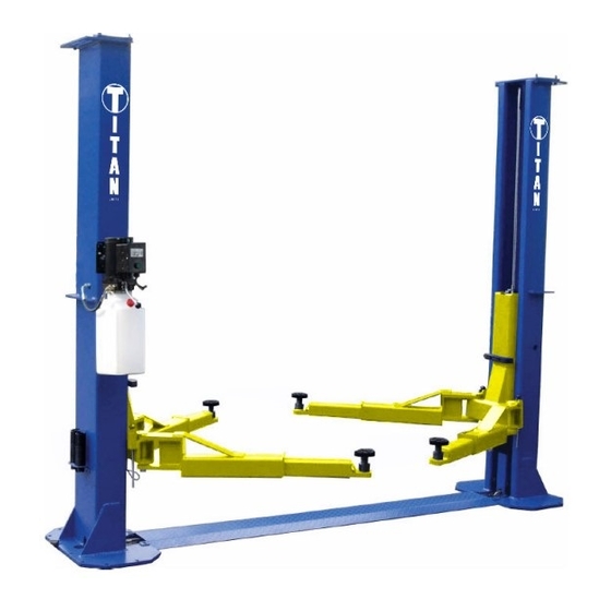
2-DESCRIPTION This lift is a 12,000 lb. capacity, symmetric arm floorplate lift. The safety system in this lift is attached to the back of the carriage to provide a single point release that saves time when operating. This lift is equipped with heavy-duty bearings and driven by two heavy- duty BL646 leaf chains, one per side. -
Page 8: 3-Unpacking & Setup
3-UNPACKING & SETUP Only skilled personnel who are familiar with the lift and this manual shall be allowed to carry out, lifting, handling, transport and unpacking operations. 3.1 DELIVERY AND CHECK OF PACKAGES When the lift is delivered, carefully unpack the lift making sure all the parts have been included. -
Page 9: Specifications
Description Capacity Overall Height Overall Width Between Posts Plate Dimensions Floorplate/ 20 1/2” x 34 1/2” HD2P-12000F 12,000 lbs 122” 148” 120 1/4” Symmetric x 3/4” *Due to minor variances in the manufacturing process, dimensions in this manual may vary slightly from the finished product. -
Page 10: Important Concrete And Anchoring Information
5.3 IMPORTANT CONCRETE AND ANCHORING INFORMATION 1. Concrete shall have compression strength of at least 3,000 PSI and a minimum thickness of 6”. Measure the length of the supplied anchor bolts in order to achieve a minimum anchor embedment of 3-1/4”. 2. -
Page 11: 6-Installation Instructions
6-INSTALLATION INSTRUCTIONS PLEASE READ THIS INSTRUCTION BEFORE STARTING TO OPERATE THE LIFT. Check for ceiling clearance to confirm the lift can be set up in your bay. 1) After unloading the lift, place it near the intended installation location. 2) Remove the shipping bands and packing materials from the unit. 3) Remove the packing brackets and bolts holding the two columns together (do not discard bolts, they are used in the assembly of the lift) 4) Once the lift location is decided, chalk the center line in the bay and ensure that the... - Page 12 11) Install the cylinders: Put one cylinder into each carriage by sliding it all the way down to the top of the cylinder mount at column base. Make sure the “tip” on the bottom of the cylinder will fix into the center hole on top of the cylinder mount in base. Pull the pre- attached leaf chain in both sides up and over the chain sheave on top of the cylinders.
- Page 13 WARNING: THE WIRING MUST COMPLY WITH LOCAL CODE. HAVE A CERTIFIED ELECTRICIAN MAKE THE ELECTRICAL HOOK-UP TO THE POWER UNIT. PROTECT EACH CIRCUIT WITH TIME DELAY FUSE OR CIRCUIT BREAKER; 208V-230V SINGLE PHASE. 60 HZ 30 AMP. WARNING: DO NOT PERFORM ANY MAINTENANCE OR INSTALLATION OF ANY COMPONENTS WITHOUT FIRST ENSURING THAT ELECTRICAL POWER HAS BEEN DISCONNECTED AT THE SOURCE OR PANEL AND CANNOT BE REENERGIZED UNTIL ALL MAINTENANCE AND/OR INSTALLATION PROCEDURES...
-
Page 14: 7-Operation Instructions
7-OPERATION INSTRUCTIONS WARNING: LIFT OPERATION BY TRAINED AUTHORIZED PERSONNEL OVER 18 YEARS ONLY. APPLY THE PARKING BRAKE AFTER POSITIONING THE VEHICLE ON THE LIFT. DO NOT ALLOW ANYONE TO STAY IN LIFT AREA DURING RAISING AND LOWERING CYCLES. CLOSELY WATCH THE VEHICLE AND THE LIFT DURING RAISING AND LOWERING CYCLES. -
Page 15: Lowering Control
NOTE: IT IS NORMAL FOR AN EMPTY LIFT TO LOWER SLOWLY - IT MAY BE NECESSARY TO ADD WEIGHT. 7.2.3 LOWERING CONTROL Press the up button enough to allow the safety locks to be disengaged. Pull both latch releases Fig. 2 to release the safety Fig. - Page 16 WARNING: Do not lift the vehicle if you cannot establish secure and level lifting points. Do not use sub-standard shims or other devices in place of approved and recommended rubber pad adapters. Never use the lift without the rubber pads in place on each plate and in contact with the lifting points of a vehicle.
-
Page 17: 8-Maintenance
8-MAINTENANCE WARNING: DISCONNECT THE POWER BEFORE SERVICING THE LIFT. IMPORTANT: THE MAINTENANCE INTERVALS INDICATED BELOW APPLY TO AVERAGE WORKSHOP USE. THE LIFT SHOULD BE INSPECTED MORE FREQUENTLY FOR SEVERE USE APPLICATIONS. 8.1 MAINTENANCE SCHEDULE It is important to keep the lift clean, dry, and well maintained by establishing a periodic preventive maintenance program to ensure trouble-free operation and long service life. -
Page 18: Monthly
8.1.3 MONTHLY 1. Check safety mechanism operation. 2. Check condition of shafts, shaft locks and bushings. 3. Check overall cleanliness. 8.1.4 BIMONTHLY 1. Check condition of extensions and lubricate. 2. Check oil leaks from cylinders. 3. Check oil leaks at pipe joints. 8.1.5 YEARLY Service and safety inspection on the lift must be performed by a competent person. -
Page 19: Maintenance By Operator
IMPORTANT: AFTER CLEANING WORKSHOP FLOOR OR LIFT, TO MAINTAIN HOIST EFFICIENCY WE ADVISE TO LUBRICATE LIFTING ARM LOCKING MECHANISM, AND SAFETY LOCKING MECHANISM. CHECK SAFETY LOCKING MECHANISM IS FUNCTIONING CORRECTLY. 8.2 MAINTENANCE BY OPERATOR All moving parts have been lubricated at the factory and should be re-lubricated before the first use and at least once every six months to prevent damage. -
Page 20: Operation And Wear Checks
8.2.3 OPERATION AND WEAR CHECKS 1. Examine lift for structural cracks, bends, or other signs of damage prior to each use. Do not use this product if worn or damaged. 2. Check that the safety locking mechanism is functioning correctly. 3. -
Page 21: 9-Troubleshooting
9-TROUBLESHOOTING Motor does not run: A. Breaker or fuse blown. B. Motor thermal overload tripped. Wait for overload to cool. C. Faulty wiring connections……Call electrician for service. Defective up button……Call electrician for service. Motor runs but will not raise: A. A piece of trash is under the check valve. Push handle down and push the up button at the same time. -
Page 22: 10-Owner/Employer Responsibilities
10-OWNER/EMPLOYER RESPONSIBILITIES The owner/employer: Shall establish procedures to periodically maintain, inspect and care for the lift in accordance with the manufactures recommended procedures to ensure it’s continued safe operations. Shall provide necessary lockout / tag outs of energy sources per ANSI Z244.1 - 1982 before beginning any lift repairs. -
Page 23: 11-Diagrams (Fig. 1-5)
11-DIAGRAMS (FIG. 1-5) FIG. 1 - DIMENSIONS 120-1/4” 148” R37-1/8” - 52-1/8” R37-1/8” - 52-1/8”... - Page 24 FIG. 2 - CABLES...
- Page 25 FIG. 3 - EXPLODED VIEW 1 25.1 27/28 15/16/17 39/40...
- Page 26 FIG. 4 - EXPLODED VIEW 2 53/54/55/56...
- Page 27 PART # CODE DESCRIPTION TT-6961KY-101-01-00A MAIN COLUMN TT-6961KY-101-01-00B OFFSIDE COLUMN TPO15-600-01-00 FLOORPLATE TT-6961KY-300-01-00 LIFTING ARM TT-6961KY-200-01-00 CARRIAGE GB895.2-1986 D35 C-CLIP TT-6961KY-048417160 THREADED SLEEVE 45 TT-6961KY-048417190L THREADED PAD MOUNT TT-6934-046405772 RUBBER PAD TPO15-300-02 ARM PIN GB70.1-2000 M8X35 HEX BOLT DL38G-C116A RUBBER DOOR GUARD TPO15-200-04 NYLON BLOCK BALL HANDLE...
- Page 28 PART # CODE DESCRIPTION GB818-85 M8X10 SCREW M8X10 TT-6961KY-103-01 TRUCK ADAPTER HOLDER TT-6961KY-300-02-00 TALL ADAPTER L=120MM TT-6961KY-300-03-00 SHORT ADAPTER L=76MM ANCHOR BOLT TPO15-505-01 STEEL CABLE GB95-85 WASHER GB889.1 M20 LOCKING NUT TT-6835-100-03 RUBBER GROMMET POWER UNIT TPO15-NEW CYLINDER COMPONENT CHAIN LH1246*115 SECTION GB5781-86 M8X25 BOLT GB95-85 D8...
- Page 29 FIG. 5 - POWER UNIT Description Overflow valve Hose fitting Annectent spindle Check valve Lowering valve Bolt Throttle valve Escape oil valve Oil Reservoir (12 Liter) Suction oil hose Gear pump Bumper valve Valve seat Motor Power Control Button Lowering Handle...
- Page 30 Titan TJ1T, FJ2T, and FJ3T are warrantied for replacement parts only to the original purchaser for a period of 1 year from the date of purchase. All non-serialized items will require proof of purchase in the form of a sales receipt from an authorized Titan Lifts dealer showing the date of purchase for any warranty consideration.
- Page 31 WARRANTY REGISTRATION In order to utilize the warranty on this Titan Lifts product, you must register your product with us. The TITANLIFTS.COM/WARRANTIES simplest way to do this is to visit and submit your information online. If you prefer to send your information through the mail, please fill out the form below and send this page to us at :...
- Page 33 NOTES...
- Page 34 NOTES...
- Page 35 NOTES...
- Page 36 WARNING The warnings, precautions and instructions in this manual cannot cover all possible conditions and situations that may occur. The operator must understand that the operator must supply common sense and examine caution factors when using this product to determine safety in all circumstances being used. ®...
Need help?
Do you have a question about the HD2P-12000F and is the answer not in the manual?
Questions and answers