Table of Contents
Advertisement
Quick Links
®
INSTALLATION, OPERATION
& MAINTENANCE MANUAL
MODELS:
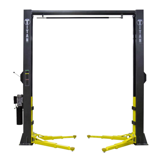
HD2P-13KCL
13,000 LB CAPACITY 2 POST LIFT
FOLLOW THIS MANUAL CAREFULLY TO ENSURE THE MACHINE WILL
FUNCTION CORRECTLY AND PROVIDE MANY YEARS OF DEPENDABLE SERVICE.
FAILURE TO FOLLOW THESE INSTRUCTIONS AND SAFETY WARNINGS MAY
RESULT IN PERSONAL INJURY OR PROPERTY DAMAGE. KEEP THIS MANUAL IN A
SAFE DRY PLACE FOR FUTURE REFERENCE.
Advertisement
Table of Contents

Related Manuals for Titan Lifts PREMIER Series


Summary of Contents for Titan Lifts PREMIER Series
- Page 1 ® INSTALLATION, OPERATION & MAINTENANCE MANUAL MODELS: HD2P-13KCL 13,000 LB CAPACITY 2 POST LIFT FOLLOW THIS MANUAL CAREFULLY TO ENSURE THE MACHINE WILL FUNCTION CORRECTLY AND PROVIDE MANY YEARS OF DEPENDABLE SERVICE. FAILURE TO FOLLOW THESE INSTRUCTIONS AND SAFETY WARNINGS MAY RESULT IN PERSONAL INJURY OR PROPERTY DAMAGE.
- Page 2 Products May Be Upgraded Without Notice Please Visit WWW.TITANLIFTS.COM For The Latest Version Of This Manual P.O. Box 7069 • Greenwood, IN 46142 • Ph. 888-908-4826 • Fx. 317-215-2770 • www.titanlifts.com...
- Page 3 Claims must be filed to cover cost. If you have any questions or if we can be of any further assistance, please don’t hesitate to contact a Titan Lifts® representative at 1-888-908-4826. Thank you for the opportunity to continue to serve your lift equipment needs.
-
Page 4: Table Of Contents
TABLE OF CONTENTS 1-SAFETY ���������������������������������������������������������������������������������������������������������������� PAGE 1 1�1 INTRODUCTION �������������������������������������������������������������������������������������������������������������������PAGE 1 1�2 SAFETY INSTRUCTIONS FOR COMMISSIONING ����������������������������������������������������������������PAGE 1 1�3 SAFETY INSTRUCTIONS FOR OPERATION �������������������������������������������������������������������������PAGE 1 1�4 SAFETY INSTRUCTIONS FOR MAINTENANCE �������������������������������������������������������������������PAGE 3 1�5 RISKS �����������������������������������������������������������������������������������������������������������������������������������PAGE 3 2-DESCRIPTION ������������������������������������������������������������������������������������������������������ PAGE 4 3-UNPACKING &... - Page 5 INSTRUCTIONS 1-SAFETY 1.1 INTRODUCTION WARNING: READ ENTIRE MANUAL AND COMPLY WITH ALL SAFETY AND SERVICE PRECAUTIONS. DEATH, PERSONAL INJURY AND / OR PROPERTY DAMAGE MAY OCCUR IF INSTRUCTIONS ARE NOT FOLLOWED CAREFULLY. Personal injury and property damage incurred due to non-compliance with these safety instructions are not covered by the product liability regulations.
- Page 6 • Maintain a safe working environment. The work area should be clean, dry, clutter free, and sufficiently lit. • Vehicle doors should be closed during the raising and lowering cycles. • Closely watch the vehicle and lift during the raising and lowering cycles. •...
- Page 7 1.4 SAFETY INSTRUCTIONS FOR MAINTENANCE • Maintenance or repair work should be done by authorized service personnel only. • Work on the electrical equipment should be done by certified licensed electricians only. • Ensure that ecologically harmful substances are disposed of in accordance with the appropriate regulations.
- Page 8 2-DESCRIPTION The following is a 2-Column hydraulic, leaf chain driven lift. The model numbers covered in this manual are designated below: HD2P-13KCL: 2-Column Overhead Beam Lift type, 13,000 lb Capacity, Symmetric Swing Arm set up. This lift is a 13,000 lb capacity, 2-Post Lift. The safety latch system is very similar to an extension ladder.
- Page 9 3-UNPACKING & SETUP Only skilled personnel who are familiar with the lift and this manual shall be allowed to carry out, lifting, handling, transport and unpacking operations. 3.1 DELIVERY AND CHECK OF PACKAGES When the lift is delivered, carefully unpack the lift making sure all the parts have been included.
- Page 10 4 SPECIFICATIONS Model Description Capacity Lifting Time Overall Height Overall Width Between Posts Clear Floor/ HD2P-13KCL 13,000 lb 40-60 sec. 151” 142.75” 117.50” Asymmetric Max Lifting Min Pad Height Drive-Thru Height 72.75” 4” 107” *Due to minor variances in the manufacturing process, dimensions in this manual may vary slightly from the finished product.
- Page 11 5.3 IMPORTANT CONCRETE AND ANCHORING INFORMATION 1. Concrete shall have compression strength of at least 3,000 PSI and a minimum thickness of 4”. Measure the length of the supplied anchor bolts in order to achieve a minimum anchor embedment of 3-1/4”. If the top of the anchor exceeds 2” above the floor grade, you DO NOT have enough embedment.
- Page 12 6-INSTALLATION INSTRUCTIONS PLEASE NOTE THAT ALL DIMENSIONS GIVEN ARE FOR REFERENCE. FINAL DIMENSIONS MAY VARY SLIGHTLY. LIFT COLUMNS MUST BE PLUMB AND SQUARE REGARDLESS OF FINAL DIMENSIONS. 1) After unloading the lift, place it near the intended installation location. 2) Remove the shipping bands and protective wrapping from the lift. Support the top column as you remove the packing frames from each end of the lift.
- Page 13 9) Measure the distance from the back of the crossbar mounting plate to the back of opposite mounting plate and set the second column this distance away from the first column that has already been anchored. (As a reference - the distance between the face of the columns should be +/- 117.50”...
- Page 14 12) You are now ready to install the equalizing cables: Route cables through carriages and around pulleys as shown in diagram. Secure cables to the carriage using one of the two supplied cable nuts on each end of the cable. (The second nut will be used as a jam nut after final adjustments are made to cable.) (Tip: When installing the cables, loosen the nut on the cable that is pointing upward inside each carriage until the end of the stud is flush with the just one nut.
- Page 15 18) Press and hold power button on motor to operate lift. Raise carriages all the way to the top of the lift, then lower carriages down to the ground to bleed air from the hydraulic system prior to adjusting cable tension. NOTE: Cables must be adjusted so that the safety locks engage simultaneously prior to lifting any weight.
-
Page 16: Up Control
7-OPERATION INSTRUCTIONS WARNING: LIFT OPERATION BY TRAINED AUTHORIZED PERSONNEL OVER 18 YEARS ONLY. APPLY THE PARKING BRAKE AFTER POSITIONING THE VEHICLE ON THE LIFT. DO NOT ALLOW ANYONE TO STAY IN LIFT AREA DURING RAISING AND LOWERING CYCLES. CLOSELY WATCH THE VEHICLE AND THE LIFT DURING RAISING AND LOWERING CYCLES. -
Page 17: Lowering Control
NOTE: IT IS NORMAL FOR AN EMPTY LIFT TO LOWER SLOWLY - IT MAY BE NECESSARY TO ADD WEIGHT. 7.2.3 LOWERING CONTROL Press the up button enough to allow the safety locks to be disengaged. Pull the latch release handle (Fig. 1) to release the safety locks. WARNING: ALWAYS ENSURE BOTH SIDES RELEASE. - Page 18 WARNING: Do not lift the vehicle if you cannot establish secure and level lifting points. Do not use sub-standard shims or other devices in place of approved and recommended rubber pad adapters. Never use the lift without the rubber pads in place on each plate and in contact with the lifting points of a vehicle.
-
Page 19: Daily
8-MAINTENANCE WARNING: DISCONNECT THE POWER BEFORE SERVICING THE LIFT. IMPORTANT: THE MAINTENANCE INTERVALS INDICATED BELOW APPLY TO AVERAGE WORKSHOP USE. THE LIFT SHOULD BE INSPECTED MORE FREQUENTLY FOR SEVERE USE APPLICATIONS. 8.1 MAINTENANCE SCHEDULE It is important to keep the lift clean, dry, lubricated and well maintained by establishing a periodic preventive maintenance program to ensure trouble-free operation and long service life. -
Page 20: Monthly
8.1.3 MONTHLY 1. Check safety mechanism operation. 2. Check condition of shafts, shaft locks and bushings. 3. Check overall cleanliness. 8.1.4 BI-MONTHLY 1. Check condition of extensions and lubricate. 2. Check oil leaks from cylinders. 3. Check oil leaks at pipe joints. 8.1.5 YEARLY Service and safety inspection on the lift must be performed by a competent person. -
Page 21: Hydraulic System
IMPORTANT: AFTER CLEANING WORKSHOP FLOOR OR LIFT, TO MAINTAIN HOIST EFFICIENCY WE ADVISE TO LUBRICATE LIFTING ARM LOCKING MECHANISM, AND SAFETY LOCKING MECHANISM. CHECK SAFETY LOCKING MECHANISM IS FUNCTIONING CORRECTLY. 8.2 MAINTENANCE BY OPERATOR All moving parts have been lubricated at the factory and should be re-lubricated before the first use and at least once every six months to prevent damage. -
Page 22: Operation And Wear Checks
8.2.3 OPERATION AND WEAR CHECKS 1. Examine lift for structural cracks, bends, or other signs of damage prior to each use. Do not use this product if worn or damaged. 2. Check that the safety locking mechanism is functioning correctly. 3. - Page 23 9-TROUBLESHOOTING 1� Motor does not run: A. Breaker or fuse blown. B. Motor thermal overload tripped. Wait for overload to cool. C. Faulty wiring connections……Call electrician for service. D. Defective up button……Call electrician for service. 2� Motor runs but will not raise: A.
- Page 24 10-OWNER/EMPLOYER RESPONSIBILITIES The owner/employer: Shall establish procedures to periodically maintain, inspect and care for the lift in accordance with the manufactures recommended procedures to ensure it’s continued safe operations. Shall provide necessary lockout / tag outs of energy sources per ANSI Z244.1 - 1982 before beginning any lift repairs.
- Page 25 11-DIAGRAMS (FIG. 1-8) FIG. 1 - HD2P-13KCL 117.50” 151.00” 4” - 72.75” 32” - 45.50” 142.75”...
- Page 26 FIG. 2 - HD2P-13KCL Column Column Anchor Bolts 3/4” 6.25” 6” Concrete 3000PSI min Torque Nut...
- Page 27 FIG. 3 - POWER UNIT Power Unit for 2-Post lift (Manual Release) Parts List (Power Unit) Desc. Item Motor Valve Body Pressure ReliefValve Plug Cushion Valve Oil Pickup Tube Oil Filter Throttle Valve Straight Fitting Release Valve Check Valve Gear Pump Reservoir Reservoir Lid Drain Tube...
- Page 28 FIG. 4 - MAIN COLUMN 14 14 30 29 28 28 28 28 28...
- Page 29 FIG. 5 - OFFSIDE COLUMN 28 28 19 18...
- Page 30 FIG. 6 - CARRIAGE...
- Page 31 FIG. 7 - CROSSBEAM...
- Page 32 FIG. 8 - CABLES & HOSES...
- Page 33 PARTS LIST ITEM DESCRIPTION QTY ITEM DESCRIPTION Main column assembly Carriage assembly Offside column assembly Lifting pad assembly Hex bolt - M8x8 Rubber lifting pad Washer - Ø8 Clip - C50 Spring washer - C25 Forearm of 2-stage straight arm assembly Copper bush - Ø29x25x16 Rear arm of 2-stage straight arm assembly Wire rope pulley...
- Page 34 ITEM DESCRIPTION Cable 10900mm Chain Hydraulic Hose 5300mm Hydraulic Hose Fitting 9/16 to 9/16 Nut for cable M16 Hydraulic Hose 4450mm Hydraulic Hose 940mm Connector to Cylinder 65mm Banjo Bolt Combination Seal T-Fitting Hydraulic Hose 430mm Connector to Power Unit 1/4 to 3/8 Safety Release Cable...
- Page 35 NOTES...
- Page 36 Titan TJ1T, FJ2T, and FJ3T are warrantied for replacement parts only to the original purchaser for a period of 1 year from the date of purchase. All non-serialized items will require proof of purchase in the form of a sales receipt from an authorized Titan Lifts dealer showing the date of purchase for any warranty consideration.
- Page 37 WARRANTY REGISTRATION In order to utilize the warranty on this Titan Lifts product, you must register your product with us. The TITANLIFTS.COM/WARRANTIES simplest way to do this is to visit and submit your information online. If you prefer to send your information through the mail, please fill out the form below and send this page to us at :...
- Page 39 NOTES...
- Page 40 WARNING The warnings, precautions and instructions in this manual cannot cover all possible conditions and situations that may occur. The operator must understand that the operator must supply common sense and examine caution factors when using this product to determine safety in all circumstances being used. TITAN MARKETING, LLC PO Box 7069 Greenwood, IN 46142 1.888.908-4826...
Need help?
Do you have a question about the PREMIER Series and is the answer not in the manual?
Questions and answers