Table of Contents
Advertisement
Quick Links
Advertisement
Table of Contents

Related Manuals for IBASE Technology SI - 83


Summary of Contents for IBASE Technology SI - 83
-
Page 1: User Manual
Digital Player SI - 83 User Manual Revision Release Date V1.0 2014/12/12... -
Page 2: Table Of Contents
SI-83 User Manual Table of Contents Setting up your system ....................v Care during use ......................vi Acknowledgments ....................... vi CHAPTER 1 INTRODUCTION ..................1 1.1 General Description ....................1 1.2 System Specifications .................... 2 1.2.1 Hardware Specifications ..................2 1.2.2 Dimensions ...................... -
Page 3: Setting Up Your System
IBASE Technology Inc. Safety Information Your SI-83 is designed and tested to meet the latest standards of safety for information technology equipment. However, to ensure your safety, it is important that you read the following safety instructions Setting up your system ... -
Page 4: Care During Use
SI-83 User Manual Care during use Do not walk on the power cord or allow anything to rest on it. Do not spill water or any other liquids on your system. When the system is turned off, a small amount of electrical current still flows. Always unplug all power, and network cables from the power outlets before cleaning the system. -
Page 5: Acknowledgments
Acknowledgments AMI is a registered trademark of AMI Software International, Inc. AMD and ATI are registered trademarks of AMD Corporation. Microsoft Windows is a registered trademark of Microsoft Corporation. FINTEK is a registered trademark of FINTEK Electronics Corporation. ... - Page 6 SI-83 User Manual...
-
Page 7: Chapter 1 Introduction
SI-83 User Manual CHAPTER 1 INTRODUCTION 1.1 General Description The “Signature Book™” SI-83 is a professional digital signage system powered ® by 4th Gen. Intel® Core i Processor with Intel HD 4600 / 4400 Integrated Graphics. It comes with dual DP and one HDMI. The slim and segregated ventilation design player comes with a chassis that provides passive cooling for better system reliability and quiet operation. -
Page 8: System Specifications
SI-83 User Manual 1.2 System Specifications 1.2.1 Hardware Specifications Model Name SI-83 System Mainboard IB983 4th Generation Intel® Core™ i7-4700EQ 2.4GHz 4th Generation Intel® Core™ i5-4400E 2.7GHz Memory 2x DDR3L-1600 MHz SO-DIMM, Max. 16GB (Non-ECC) I/O Interface 1 x HDMI 2 x DP 2 x USB 3.0 ports, 2x USB 2.0 port 2 x RJ45 for GbE LAN, 1x RJ45 for RS232... -
Page 9: Dimensions
1.2.2 Dimensions... -
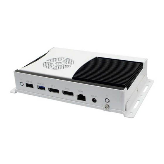
Page 10: I/O View
SI-83 User Manual 1.2.3 I/O View SI-83 front side SI-83 rear side... -
Page 11: Exploded View Of The Si-83 Assembly
1.3 Exploded View of the SI-83 Assembly... -
Page 12: Parts Description
SI-83 User Manual 1.3.1 Parts Description Part No. Description Part No. Description SI-83 heat sink SI-83 fan bracket IB983 motherboard SI-83 body case SI-83 base SI-83 system base bracket Antenna SI-83 label SI-83 board bracket SI-83 top gasket 12/13 SI-83 I/O gasket-1/2... -
Page 13: Packing List
1.4 Packing List Item No. Description Driver CD Power adaptor Power cord Mounting kit 1.4.1 Optional Items Description WiFi Solution Wireless; PCI-E Mini Card 802.11B/G/N WiFi module [AW-NE238H] (A008WLAWNE238H000P) External Antenna, WiFi Antenna (A055RFA02C2M20800P) 2pcs Internal Antenna 100mm[ BTC130-1-70B-100] Internal cable RoHS (A055RFA0000021000P) Internal Antenna 200mm [ BTC130-1-70B-200-1] Internal cable... -
Page 14: Hardware Installation
SI-83 User Manual 1.5 HARDWARE INSTALLATION 1.5.1 Installing the Mounting Kit 1. Please install the mounting kit and make sure the direction. And then screw two screws as shown. -
Page 15: Installing The Optional Wireless Module
1.5.2 Installing the Optional Wireless Module 1. Remove the two screws on the back cover that are used to secure the cover to the chassis. Once all the screws are removed, from the side, dismount the cover forward to remove it. 2. - Page 16 SI-83 User Manual 3. Remove the eight screws indicated on the picture below and remove the motherboard. 4. Install the internal cable on the “ㄇ” type bracket. Please pay attention to the length of two internal cables. Internal Antenna [A055RFA0000021000P] 10cm Internal Antenna [ A055RFA0000020000P] 20cm...
- Page 17 5. Install the motherboard and bracket, and arrange the longer right cable as shown. 6. Screw the two screws and note to the orientation of the WIFI module and bracket. 7. Push the WIFI module into the slot and connect the two internal antenna as shown below.
-
Page 18: Installing Msata
SI-83 User Manual 1.5.3 Installing mSATA 1. Remove the 2 screws on the back cover that are used to secure the cover to the chassis. Once all the screws are removed, from the side, dismount the cover forward to remove it. 2. -
Page 19: Mounting Bracket Solution
1.5.4 SI-83 Mounting Bracket Solution SI-83 mounting bracket (IBASE) part number: SC2SIMK3---0A1100P Please install SI-83 to the mounting bracket using 4 screws, as shown in the picture. -
Page 20: Chapter 2 Motherboard Introduction
SI-83 User Manual CHAPTER 2 MOTHERBOARD INTRODUCTION 2.1 Introduction The IB983 CUSTOM SIGNAGE SBC is based on the latest Intel® QM87 chipset. The platform supports onboard 4th generation Intel® Core processor family that features an integrated dual-channel DDR3 memory controller as well as a graphics core. The latest Intel®... - Page 21 Edge I/O Display 1x HDMI 1.4a 2x DP v1.3 LAN / PHY 1x GbE with Intel® WGI217LM 1x GbE with Realtek RTL8111G-CG Audio Intel® QM87 PCH built-in HD audio controller + ALC892 w/ 7.1 channels 1x Audio Connector (Lin out) 2x USB 3.0;...
-
Page 22: Ib983 Jumpers And Connectors
SI-83 User Manual IB983 Jumpers and Connectors... - Page 23 Board Dimensions...
-
Page 24: Installations
SI-83 User Manual 2.2 Installations 2.2.1 Installing the Memory The IB983 board supports two DDR3 memory sockets for a maximum total memory of 16GB DDR3 memory type. Installing and Removing Memory Modules To install the DDR3 modules, locate the memory slot on the board and perform the following steps: 1. -
Page 25: Setting The Jumpers
2.3 Setting the Jumpers Jumper Locations on IB983 JP1: Clear CMOS Contents Setting Function Pin 1-2 Normal Short/Closed Pin 2-3 Clear CMOS Short/Closed JP2: Clear ME Contents... - Page 26 SI-83 User Manual Setting Function Pin 1-2 Normal Short/Closed Pin 2-3 Clear CMOS Short/Closed...
-
Page 27: Connectors On Ib983
2.4 Connectors on IB983 Connector Locations on IB983 CN1: Board Input Power(12V) Connector CN2: Console Port ( COM1) The console port is an RJ45 RS-232 serial port. Pin # Signal Name CN3, 4: Display Port... - Page 28 SI-83 User Manual CN5, CN8: USB2.0 Connector CN6, CN7: USB3.0 Connector CN9: Gigabit LAN (RTL8111G) RJ45 Connector...
- Page 29 CN10: Gigabit LAN (I217) RJ45 Connector CN11: HDMI Port CN12: HD Audio (Audio out) Connector CN13: Micro SIM Card Connector...
- Page 30 SI-83 User Manual J1, J9: DDR3 SO-DIMM Socket J4: Mini PCIE Connector J5: mSATA Connector...
- Page 31 J7: CPU Fan Power Connector Signal Name Pin # Ground +12V Rotation detection J8: SPI Flash Connector (Factory use only) J10: LPC debug Connector (Factory use only) SW1: Power Switch...
-
Page 32: Chapter 3 Bios Setup
SI-83 User Manual CHAPTER 3 BIOS SETUP This chapter describes the different settings available in the AMI BIOS that comes with the board. The topics covered in this chapter are as follows: 3.1 BIOS Introduction The BIOS (Basic Input/Output System) installed in your computer system’s ROM supports Intel processors. - Page 33 Warning: It is strongly recommended that you avoid making any changes to the chipset defaults. These defaults have been carefully chosen by both AMI and your system manufacturer to provide the absolute maximum performance and reliability. Changing the defaults could cause the system to become unstable and crash in some cases.
-
Page 34: Advanced Settings
SI-83 User Manual Advanced Settings This section allows you to configure and improve your system and allows you to set up some system features according to your preference. Aptio Setup Utility Advanced Main Chipset Boot Security Save & Exit ► ACPI Settings ►... - Page 35 Trusted Computing Aptio Setup Utility Advanced Main Chipset Boot Security Save & Exit Configuration Security Device Support Disabled → ← Select Screen ↑↓ Select Item Enter: Select +- Change Field Current Status Information F1: General Help F2: Previous Values SUPPORT TURNED OFF F3: Optimized Default F4: Save ESC: Exit...
- Page 36 SI-83 User Manual CPU Configuration This section shows the CPU configuration parameters. Aptio Setup Utility Advanced Main Chipset Boot Security Save & Exit CPU Configuration Intel(R) CPU Core(TM)i7-4700EQE @ 2.40GHz CPU Signature 306c3 Processor Family Microcode Patch FSB Speed 100MHz Max CPU Speed 2400 MHz Min CPU Speed...
- Page 37 Execute Disable Bit XD can prevent certain classes of malicious buffer overflow attacks when combined with a supporting OS Intel Virtualization Technology When enabled, a VMM can utilize the additional hardware capabilities provided by Vanderpool Technology. EIST Enabled/Disabled Intel Speedstep. SATA Configuration SATA Devices Configuration.
- Page 38 SI-83 User Manual Shutdown Temperature Configuration Aptio Setup Utility Advanced Main Chipset Boot Security Save & Exit → ← Select Screen APCI Shutdown Temperature Disabled ↑↓ Select Item Enter: Select +- Change Field F1: General Help F2: Previous Values F3: Optimized Default F4: Save ESC: Exit ACPI Shutdown Temperature...
- Page 39 AMT Configuration Aptio Setup Utility Advanced Main Chipset Boot Security Save & Exit Intel AMT Enabled BIOS Hotkey Pressed Disabled MEBx Selection Screen Disabled Hide Un-Configure ME Confirmation Disabled Un-Configure ME Disabled Amt Wait Timer Activate Remote Assistance Process Disabled USB Configure Enabled PET Progress...
- Page 40 SI-83 User Manual Hide Un-Configure ME Confirmation OEMFLag Bit 15: Un-Configure ME without password Amt Wait Timer Set timer to wait before sending ASF_GET_BOOT_OPTIONS. Disable ME Set ME to Soft Temporary Disabled. Activate Remote Assistance Process Trigger CIRA boot. USB Configure Enable/Disable USB Configure function.
- Page 41 USB Configuration Aptio Setup Utility Advanced Main Chipset Boot Security Save & Exit USB Configuration USB Module Version 8.10.28 USB Devices: Legacy USB Support Enabled USB3.0 Support Enabled XHCI Hand-off Enabled EHCI Hand-off Enabled USB Mass Storage Driver Support Enabled Port 60/64 Emulation Enabled →...
- Page 42 SI-83 User Manual USB Mass Storage Driver Support Enable/Disable USB Mass Storage Driver Support. Port 60/64 Emulation Enables I/O port 60h/64h emulation support. This should be enabled for the complete USB keyboard legacy support for non-USB aware OSes. USB Transfer time-out The time-out value for Control, Bulk, and Interrupt transfers.
- Page 43 Chipset Settings This section allows you to configure and improve your system and allows you to set up some system features according to your preference. Aptio Setup Utility Advanced Main Chipset Boot Security Save & Exit → ← Select Screen ►...
- Page 44 SI-83 User Manual USB Configuration Chipset Main Advanced Boot Security Save & Exit USB Configuration USB Precondition Disabled xHCI Mode Smart Auto BTCG Enabled → ← Select Screen ↑↓ Select Item Enter: Select +- Change Field USB Ports Per-Port Disable Control Disabled F1: General Help F2: Previous Values...
- Page 45 PCH Azalia Configuration Chipset Main Advanced Boot Security Save & Exit PCH Azalia Configuration → ← Select Screen ↑↓ Select Item Enter: Select Azalia Auto +- Change Field F1: General Help F2: Previous Values F3: Optimized Default F4: Save ESC: Exit Azalia Control Detection of the Azalia device.
- Page 46 SI-83 User Manual Graphics Configuration Aptio Setup Utility Chipset Main Advanced Boot Security Save & Exit Graphics Configuration IGFX VBIOS Version 2167 IGfx Frequency 800 MHz Graphics Turbo IMON Current Primary Display Auto Primary PEG Auto Primary PCIE Auto Internal Graphics Auto →...
- Page 47 Aperture Size Select the Aperture Size DVMT Pre-Allocated Select DVMT 5.0 Pre-Allocated (Fixed) Graphics memory size used by the internal graphics device. DVMT Total Gfx Mem Select DVMT 5.0 total graphics memory size used by the internal graphics device. Gfx Low Power Mode This option is applicable for SFF only.
- Page 48 SI-83 User Manual Boot Settings Aptio Setup Utility Boot Main Advanced Chipset Security Save & Exit Boot Configuration Setup Prompt Timeout Bootup NumLock State Quiet Boot Disabled Fast Boot Disabled Set Boot Priority 1st Boot CD/DVD 2nd Boot Hard Disk 3rd Boot USb Floppy 4th Boot...
- Page 49 Set Boot Priority Set Boot Priority Boot Option Priorities Sets the system boot order. CSM parameters This section allows you to configure the boot settings. Aptio Setup Utility Boot Main Advanced Chipset Security Save & Exit Launch CSM Enabled Boot option filter UEFI and Legacy →...
-
Page 50: Security Settings
SI-83 User Manual Security Settings This section allows you to configure and improve your system and allows you to set up some system features according to your preference. Aptio Setup Utility Security Main Advanced Chipset Boot Save & Exit Password Description If ONLY the Administrator’s password is set, then this only limit access to Setup and is only asked for when entering Setup. - Page 51 Save & Exit Settings Aptio Setup Utility Advanced Main Chipset Boot Security Save & Exit Save Changes and Exit Discard Changes and Exit Save Changes and Reset Discard Changes and Reset Save Options → ← Select Screen Save Changes ↑↓ Select Item Discard Changes Enter: Select +- Change Field...
-
Page 52: Chapter 4 Drivers Installation
SI-83 User Manual CHAPTER 4 DRIVERS INSTALLATION The Intel Chipset Drivers should be installed first before the software drivers to enable Plug & Play INF support for Intel chipset components. Follow the instructions below to complete the installation. 4.1 Intel Chipset Software Installation Utility 1. - Page 53 3. When the Welcome screen to the Intel® Chipset Device Software appears, click Next to continue. 4. Click Yes to accept the software license agreement and proceed with the installation process. 5. On the Readme File Information screen, click Next to continue the installation. 6.
-
Page 54: Vga Drivers Installation
SI-83 User Manual 4.2 VGA Drivers Installation 1. Insert the DVD that comes with the board. Click Intel and then Intel(R) 8 Series Chipset Drivers. 2. Click Intel(R) Core(TM) i3/i5/i7 Graphics Driver. 3. When the Welcome screen appears, click Next to continue. 4. - Page 55 5. On the screen shown below, click Install to continue. 6. Setup complete. Click Finish to restart the computer and for changes to take effect.
-
Page 56: Realtek Hd Audio Driver Installation
SI-83 User Manual 4.3 Realtek HD Audio Driver Installation 1. Insert the DVD that comes with the board. Click Intel and then Intel(R) 8 Series Chipset Drivers. 2. Click Realtek High Definition Audio Driver. - Page 57 3. On the Welcome to the InstallShield Wizard screen, click Yes to proceed with and complete the installation process. 4. The InstallShield Wizard Complete. Click Finish to restart the computer and for changes to take ffect.
-
Page 58: Lan Drivers Installation
SI-83 User Manual 4.4 LAN Drivers Installation 1. Insert the DVD that comes with the board. Click Intel and then Intel(R) 8 Series Chipset Drivers. 2. Click Intel(R) PRO LAN Network Driver. - Page 59 3. Click Install Drivers and Software. 4. When the Welcome screen appears, click Next. 5. Click Next to to agree with the license agreement. 6. Click the checkbox for Drivers in the Setup Options screen to select it and click Next to continue.
- Page 60 SI-83 User Manual 7. The wizard is ready to begin installation. Click Install to begin the installation. 8. When InstallShield Wizard is complete, click Finish.
-
Page 61: Realtek Lan Controller Drivers Installation
4.5 Realtek LAN Controller Drivers Installation Follow the steps below to install the Realtek LAN Drivers. 1. Insert the CD that comes with the board. Click LAN Card, and then Realtek Lan Controller Drivers. 2. Click Realtek RTL8111E LAN Drivers. - Page 62 SI-83 User Manual 3.When the welcome screen to InstallShield Wizard appears, click Next to start the installation. 4.When the InstallShieldWizard has finished installing the Realtek LAN drivers, click Finish.
-
Page 63: Intel® Management Engine Interface
4.6 Intel® Management Engine Interface Follow the steps below to install the Intel Management Engine. 1. Insert the DVD that comes with the board. Click Intel and then Intel(R) 8 Series Chipset Drivers and then Intel(R) AMT 9.0 Drivers. - Page 64 SI-83 User Manual 2. When the Welcome screen to the InstallShield Wizard for Intel® Management Engine Components, click the checkbox for Install Intel® Control Center & click Next. 3. Click Yes to to agree with the license agreement.
- Page 65 4. When the Setup Progress screen appears, click Next. Then, click Finish when the setup progress has been successfully installed.
-
Page 66: Intel® Usb 3.0 Drivers
SI-83 User Manual 4.7 Intel® USB 3.0 Drivers 1. Insert the DVD that comes with the board. Click Intel and then Intel(R) 8 Series Chipset Drivers. 2. Click Intel(R) USB 3.0 Drivers. - Page 67 3. When the Welcome screen to the InstallShield Wizard for Intel® USB 3.0 eXtensible Host Controller Driver, click Next. 4. Click Yes to to agree with the license agreement and continue the installation.
- Page 68 SI-83 User Manual 5. On the Readme File Information screen, click Next to continue the installation of the Intel® USB 3.0 eXtensible Host Controller Driver. 6. Setup complete. Click Finish to restart the computer and for changes to take effect.
-
Page 69: Appendix
Appendix A. I/O Port Address Map Each peripheral device in the system is assigned a set of I/O port addresses which also becomes the identity of the device. The following table lists the I/O port addresses used. Address Device Description 0000h-001Fh Direct memory access controller 0000h-0001h... -
Page 70: Interrupt Request Lines (Irq)
SI-83 User Manual B. Interrupt Request Lines (IRQ) Peripheral devices use interrupt request lines to notify CPU for the service required. The following table shows the IRQ used by the devices on board. Level Function IRQ0 System timer IRQ4 Serial Port #1 IRQ8 System CMOS / real time clock IRQ11... -
Page 71: Watchdog Timer Configuration
C. Watchdog Timer Configuration The WDT is used to generate a variety of output signals after a user programmable count. The WDT is suitable for use in the prevention of system lock-up, such as when software becomes trapped in a deadlock. Under these sorts of circumstances, the timer will count to zero and the selected outputs will be driven. - Page 72 SI-83 User Manual File of the MAIN.CPP. //--------------------------------------------------------------------------- // THIS CODE AND INFORMATION IS PROVIDED "AS IS" WITHOUT WARRANTY OF ANY // KIND, EITHER EXPRESSED OR IMPLIED, INCLUDING BUT NOT LIMITED TO THE // IMPLIED WARRANTIES OF MERCHANTABILITY AND/OR FITNESS FOR A PARTICULAR // PURPOSE.
- Page 73 //--------------------------------------------------------------------------- int main (void) char SIO; SIO = Init_NCT5523D(); if (SIO == 0) printf("Can not detect Nuvoton NCT5523D, program abort.\n"); return(1); WDTInitial(); WDTEnable(10); WDTDisable(); return 0; //--------------------------------------------------------------------------- void WDTInitial(void) unsigned char bBuf; Set_NCT5523D_LD(0x08); //switch to logic device 8 bBuf = Get_NCT5523D_Reg(0x30); bBuf &= (~0x01);...
- Page 74 SI-83 User Manual Set_NCT5523D_Reg(0xF1, NewInterval); //set timer //--------------------------------------------------------------------------- void WDTDisable(void) Set_NCT5523D_LD(0x08); //switch to logic device 8 Set_NCT5523D_Reg(0xF1, 0x00); //clear watchdog timer Set_NCT5523D_Reg(0x30, 0x00); //watchdog disabled //--------------------------------------------------------------------------- File of the NCT5523D.CPP //--------------------------------------------------------------------------- // THIS CODE AND INFORMATION IS PROVIDED "AS IS" WITHOUT WARRANTY OF ANY // KIND, EITHER EXPRESSED OR IMPLIED, INCLUDING BUT NOT LIMITED TO THE // IMPLIED WARRANTIES OF MERCHANTABILITY AND/OR FITNESS FOR A PARTICULAR // PURPOSE.
- Page 75 void Unlock_NCT5523D (void); void Lock_NCT5523D (void); //--------------------------------------------------------------------------- unsigned int Init_NCT5523D(void) unsigned int result; unsigned char ucDid; NCT5523D_BASE = 0x4E; result = NCT5523D_BASE; ucDid = Get_NCT5523D_Reg(0x20); if (ucDid == 0xC4) //NCT5523D?? { goto Init_Finish; } NCT5523D_BASE = 0x2E; result = NCT5523D_BASE; ucDid = Get_NCT5523D_Reg(0x20);...
- Page 76 SI-83 User Manual //--------------------------------------------------------------------------- void Set_NCT5523D_LD( unsigned char LD) Unlock_NCT5523D(); outportb(NCT5523D_INDEX_PORT, NCT5523D_REG_LD); outportb(NCT5523D_DATA_PORT, LD); Lock_NCT5523D(); //--------------------------------------------------------------------------- void Set_NCT5523D_Reg( unsigned char REG, unsigned char DATA) Unlock_NCT5523D(); outportb(NCT5523D_INDEX_PORT, REG); outportb(NCT5523D_DATA_PORT, DATA); Lock_NCT5523D(); //--------------------------------------------------------------------------- unsigned char Get_NCT5523D_Reg(unsigned char REG) unsigned char Result; Unlock_NCT5523D(); outportb(NCT5523D_INDEX_PORT, REG);...
Need help?
Do you have a question about the SI - 83 and is the answer not in the manual?
Questions and answers