Table of Contents
Advertisement
Advertisement
Table of Contents

Related Manuals for Invertek Drives Optidrive ODE-2-12005-1H01 01 Series


Summary of Contents for Invertek Drives Optidrive ODE-2-12005-1H01 01 Series
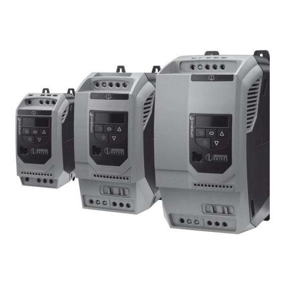
- Page 1 Optidrive E2 Single Phase Output User Guide V3.10 User Guide Single Phase Output AC Variable Speed Drive for PSC & Shaded Pole Single Phase Motors 0.37 – 1.1kW / 0.5 – 1.5HP IP20 Open & IP66 (Nema 4X) Enclosed Units Installation and Operating Instructions...
- Page 2 Optidrive E2 Single Phase Output User Guide V3.10 AC Supply Voltage Supply Voltage: (50/60Hz) - 115, 230V - 1 phase Earth - check drive rating information on page 27 Fuses or MCB & cable sizes: Fuses or MCB - check drive rating information on page 27 Mechanical Mounting: - Information can be found on page 9 Keypad Operation can be found on page 16...
- Page 3 Optidrive E2 Single Phase Output User Guide V3.10 Switched Enclosure Variant only: Local Speed Potentiometer: The local speed potentiometer will Mechanical Mounting: adjust the output frequency from - Information can be found on minimum speed P-02=0Hz to maximum page 9 speed P-01=50Hz (60Hz for HP rated drives) Minimum speed P-02 = 0Hz...
- Page 4 User Guide Revision 3.10 Invertek Drives Ltd adopts a policy of continuous improvement and whilst every effort has been made to provide accurate and up to date information, the information contained in this User Guide should be used for guidance purposes only and does not form the part of any contract.
-
Page 5: Table Of Contents
Optidrive E2 Single Phase Output User Guide V3.10 Introduction ..................................6 1.1. Important Safety Information General Information and Ratings ............................7 2.1. Identifying the Drive by Model Number 2.2. Drive Model Numbers Mechanical Installation ..............................8 3.1. General 3.2. Before Installation 3.3. -
Page 6: Introduction
Optidrive E2 Single Phase Output User Guide V3.10 1. Introduction 1.1. Important Safety Information Please read the IMPORTANT SAFETY INFORMATION below, and all Warning and Caution information elsewhere. Danger : Indicates a risk of electric shock, which, if not Danger : Indicates a potentially hazardous situation avoided, could result in damage to the equipment and other than electrical, which if not avoided, could result possible injury or death. -
Page 7: General Information And Ratings
Optidrive E2 Single Phase Output User Guide V3.10 2. General Information and Ratings This chapter contains information about the Optidrive E2 including how to identify the drive 2.1. Identifying the Drive by Model Number Each drive can be identified by its model number, as shown in the table below. The model number is on the shipping label and the drive nameplate. -
Page 8: Mechanical Installation
The enclosure design and layout should ensure that the adequate ventilation paths and clearances are left to allow air to circulate through the drive heatsink. Invertek Drives recommend the following minimum sizes for drives mounted in non-ventilated metallic enclosures:- www.invertekdrives.com... -
Page 9: Mechanical Dimensions - Ip66 (Nema 4X) Enclosed Units
Optidrive E2 Single Phase Output User Guide V3.10 Drive Recommended Size Above & Either Between airflow Below Side CFM (ft /min) 1.97 1.97 1.30 2.95 1.97 1.81 Note : Dimension Z assumes that the drives are mounted side-by-side with no clearance. Typical drive heat losses are 3% of operating load conditions. -
Page 10: Gland Plate And Lock Off
Optidrive E2 Single Phase Output User Guide V3.10 3.8. Gland Plate and Lock Off The use of a suitable gland system is required to maintain the appropriate IP / Nema rating. The gland plate has pre moulded cable entry holes for power and motor connections suitable for use with glands as shown in the following table. -
Page 11: Ip66 (Nema 4X) Enclosure Layout
Optidrive E2 Single Phase Output User Guide V3.10 3.11. IP66 (Nema 4X) Enclosure Layout 3.11.1. IP66 (Nema 4X) Switched Unit Local Speed Potentiometer Drive LED Display REV / 0 / FWD Drive LED Display Selector Switch Keypad Keypad Local Power Isolator Control Terminals Removable Cover... -
Page 12: Power Wiring
Grounding the Drive This manual is intended as a guide for proper installation. Invertek Drives Ltd cannot assume responsibility for the compliance or the non-compliance to any code, national, local or otherwise, for the proper installation of this drive or associated equipment. A hazard of personal injury and/or equipment damage exists if codes are ignored during installation. -
Page 13: Incoming Power Connection
Optidrive E2 Single Phase Output User Guide V3.10 4.3. Incoming Power Connection Power should be connected to the L1/L, L2/N terminals. For compliance with CE and C Tick EMC requirements, a symmetrical shielded cable is recommended. A fixed installation is required according to IEC61800-5-1 with a suitable disconnecting device installed between the Optidrive and the AC Power Source. -
Page 14: Connection Diagram - Ip20 Open & Ip66 (Nema 4X) Non Switched Units
Optidrive E2 Single Phase Output User Guide V3.10 4.7. Connection Diagram – IP20 Open & IP66 (Nema 4X) Non Switched Units Power Connections Incoming Power Supply Isolator / Disconnect MCB or Fuse Optional Input Choke Optional Input Filter L1/L Optional Brake Resistor L2/N Shielded Motor Cable Analog Output... -
Page 15: Using The Rev/0/Fwd Selector Switch (Switched Version Only)
Optidrive E2 Single Phase Output User Guide V3.10 4.9. Using the REV/0/FWD Selector Switch (Switched Version Only) By adjusting the parameter settings the Optidrive can be configured for multiple applications and not just for Forward operation. This could typically be for Hand/Off/Auto applications (also known and Local/Remote) for HVAC and pumping industries. Parameters to Set Switch Position Notes... -
Page 16: Operation
Optidrive E2 Single Phase Output User Guide V3.10 5. Operation 5.1. Managing the Keypad The drive is configured and its operation monitored via the keypad and display. Used to display real-time information, to access and exit NAVIGATE parameter edit mode and to store parameter changes Used to increase speed in real-time mode or to increase parameter values in parameter edit mode Used to decrease speed in real-time mode or to decrease... -
Page 17: Single Phase Motor - Boost Starting Cycle
Optidrive E2 Single Phase Output User Guide V3.10 5.4. Single Phase Motor - Boost Starting cycle In order to provide a reliable method for starting the motor, a special technique is used. The motor is started immediately at rated frequency, whilst the voltage is ramped from an initial Boost Voltage (set in P-11) to the Motor Rated Voltage (set in P-07) over a Boost Period Duration (set in P-33). -
Page 18: Standard Parameters
Optidrive E2 Single Phase Output User Guide V3.10 6. Parameters 6.1. Standard Parameters Par. Description Minimum Maximum Default Units P-01 Maximum Frequency / Speed Limit P-02 120.0 50.0 (60.0) Hz / Rpm Maximum output frequency or motor speed limit – Hz or rpm. If P-10 >0, the value entered / displayed is in Rpm P-02 Minimum Frequency / Speed Limit P-01... -
Page 19: Extended Parameters
Optidrive E2 Single Phase Output User Guide V3.10 6.2. Extended Parameters Par. Description Minimum Maximum Default Units P-15 Digital Input Function Select Defines the function of the digital inputs depending on the control mode setting in P-12. See section 7, Analog and Digital Input Configurations for more information. - Page 20 Optidrive E2 Single Phase Output User Guide V3.10 Par. Description Minimum Maximum Default Units P-30 Terminal Mode Restart function Auto-0 Defines the behaviour of the drive relating to the enable digital input and also configures the Automatic Restart function. : Following Power on or reset, the drive will not start if Digital Input 1 remains closed. The Input must be closed after a power on or reset to start the drive.
-
Page 21: Adjusting The Voltage / Frequency (V/F) Characteristics
Optidrive E2 Single Phase Output User Guide V3.10 Par. Description Minimum Maximum Default Units When P-44 = 0, this parameter sets the preset digital reference (setpoint) used for the PI Controller P-46 PI Feedback Source Select 0 : Analog Input 2 (Terminal 4) 1 : Analog Input 1 (Terminal 6) 2 : Motor Current 3 : DC Bus Voltage Scaled 0 –... -
Page 22: Read Only Status Parameters
Optidrive E2 Single Phase Output User Guide V3.10 6.4. P-00 Read Only Status Parameters Description Display range Explanation 1st Analog input value 100% = max input voltage 0 … 100% 2nd Analog input value 100% = max input voltage 0 …... -
Page 23: Analog And Digital Input Configurations
Optidrive E2 Single Phase Output User Guide V3.10 7. Analog and Digital Input Configurations 7.1. Terminal Mode (P-12 = 0) P-15 Digital input 1 (T2) Digital input 2 (T3) Digital input 3 (T4) Analog input (T6) Comments Open: Stop (disable) Open : Analog speed ref No Effect Analog input 1 reference... -
Page 24: Keypad Mode (P-12 = 1 Or 2)
1 No effect Closed: Run (enable) Closed : keypad speed ref Open: Trip, Closed: Run closed, depending on P-31 setting Further information the MODBUS RTU Register Map information and communication setup; please contact your Invertek Drives Sales Partner. www.invertekdrives.com... -
Page 25: User Pi Control Mode
Optidrive E2 Single Phase Output User Guide V3.10 7.4. User PI Control Mode P-15 Digital input 1 (T2) Digital input 2 (T3) Digital input 3 (T4) Analog input (T6) Comments 0, 2, 4, Analog Input 1 can provide Open: Stop (disable) Open : PI control PI feedback analog input No Effect... -
Page 26: Modbus Rtu Communications
The Register number for each parameter P-04 to P-047 is defined as 128 + Parameter number, e.g. for parameter P-15, the register number is 128 + 15 = 143. Internal scaling is used on some parameters, for further details; please contact your Invertek Drives Sales Partner. -
Page 27: Technical Data
All Optidrive E2 units have phase imbalance monitoring. A phase imbalance of > 3% will result in the drive tripping. For input supplies which have supply imbalance greater than 3% (typically the Indian sub- continent & parts of Asia Pacific including China) Invertek Drives recommends the installation of input line reactors. Frequency 50 –... -
Page 28: Trouble Shooting
Optidrive E2 Single Phase Output User Guide V3.10 10. Trouble Shooting 10.1. Fault Code Messages Fault Code Description Corrective Action Factory Default parameters Press STOP key, drive is ready to configure for particular application have been loaded Over current on drive output. Motor at constant speed: investigate overload or malfunction.
Need help?
Do you have a question about the Optidrive ODE-2-12005-1H01 01 Series and is the answer not in the manual?
Questions and answers