Table of Contents
Advertisement
Quick Links
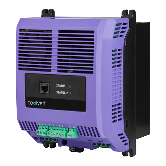
AC Variable Speed Drive
7.0 – 20.0A 200V Single Phase Input
14.0 – 58.0A 400V Three Phase Input
1 2 3
4 5 6 7 8 9
EMC
L1 L2 L3
Please scan the QR code
to access the complete User Manual
Or visit
www.invertekdrives.com/coolvert/documentation
STATUS 1
STATUS 2
1 2 3
4 5 6 7 8 9
10 11
L1 L2 L3
EMC
U
V
W
STATUS 1
STATUS 2
1 2 3
L1 L2 L3
10 11
EMC
U
V
W
STATUS 1
STATUS 2
4 5 6 7 8
10 11
U
V
W
Advertisement
Table of Contents

Subscribe to Our Youtube Channel
Related Manuals for Invertek Drives OPTIDRIVE coolvert CV-220070-1FHP


Summary of Contents for Invertek Drives OPTIDRIVE coolvert CV-220070-1FHP
- Page 1 AC Variable Speed Drive 7.0 – 20.0A 200V Single Phase Input 14.0 – 58.0A 400V Three Phase Input STATUS 1 STATUS 2 STATUS 1 STATUS 1 STATUS 2 STATUS 2 1 2 3 4 5 6 7 8 10 11 L1 L2 L3 1 2 3 4 5 6 7 8 9...
-
Page 2: Important Safety Information
Do not attempt to carry out any repair of the Optidrive. In the case of suspected fault or malfunction, contact your local Invertek Drives Sales Partner for further assistance. 2 | Coolvert Quick Start User Guide | Version 1.00 www.invertekdrives.com... -
Page 3: Product Introduction
2 PRODUCT INTRODUCTION The product range has been specifically designed for OEM and machine-builders alike with through panel mounting and cold-plate technology options available. The drive has no built-in keypad display but the status of the drive is indicated by 2 LED’s on the front of the drive. -
Page 4: Mechanical Installation
3 INSTALLATION 3.1. Mechanical Installation 3.1.1. General The Optidrive Coolvert has been designed to be installed in a suitable enclosure. The drive can be through panel mounted or mounted directly onto the back of a panel using the appropriate mounting kit. Using the drive as a template, or the dimensions shown below, mark the locations for drilling. - Page 5 3.2. Mechanical Installation 3.2.1. Frame Size 2 Heatsink drives L1 L2 L3 A B C STATUS 1 STATUS 2 1 2 3 4 5 6 7 8 9 10 11 L1 L2 L3 226.3 8.9 215.2 8.5 201.4 7.9 165.3 6.5 144.8 5.7 182 7.2 177 6.96 71.7 2.82 104.4 4.
- Page 6 3.2.3. Frame Size 3 Heatsink drives L1 L2 L3 A B C STATUS 1 STATUS 2 1 2 3 4 5 6 7 8 9 10 11 L1 L2 L3 277.5 10.9 262.6 10.3 247.2 9.7 193.6 7.6 168.9 6.6 224.0 8.8 200.3 7.9 84.3 3.3 1 16.0 4.6 170.0 6.7 3.2.4.
- Page 7 3.2.5. Frame Size 4 Heatsink drives A B C STATUS 1 STATUS 2 1 2 3 4 5 6 7 8 10 11 L1 L2 L3 310 12.2 336 13.3 364 14.3 239.5 9.4 5.9 291.5 1 1.5 230.6 9. 1 5.2 209.5 8.2 3.2.6.
- Page 8 3.2.7. Panel Mounting with Panel Mounting Kit If the installation does not lend itself to through panel mounting, the drive can be mounted to a back-plate of a panel using the optional panel mounting kit. Size 2 STATUS 1 STATUS 2 1 2 3 4 5 6 7 8 9 10 11...
- Page 9 Size 4 STATUS 1 STATUS 2 1 2 3 4 5 6 7 8 10 11 L1 L2 L3 12.2 13.2 14.3 239.5 363.5 14.3 233.5 100.4 3.2.8. Through Panel Mounting Through panel mounting is the most efficient installation in terms of both panel space and thermal management. With the heatsink protruding through the back of the electrical panel, the heat generated by the drive will be exhausted outside of the electrical panel.
- Page 10 Size 3 STATUS 1 STATUS 2 1 2 3 4 5 6 7 8 9 10 11 L1 L2 L3 277.5 10.9 18.8 0.75 227. 1 8.94 16.7 0.65 193.6 7.6 173. 1 6.8 200.3 84.3 1 16 Size 4 STATUS 1 STATUS 2 1 2 3...
- Page 11 3.2.9. Ventilation and Clearances In order for the drive to maintain it’s temperature, a minimum clearance is required around the drive as shown in the diagram below: STATUS 1 STATUS 2 1 2 3 4 5 6 7 8 9 10 11 L1 L2 L3 Frame...
-
Page 12: Connection Diagram
3.2. Connection Diagram All power terminal locations are marked directly on the product with AC power input and motor connections located at the bottom of the unit. 3.2.1. Electrical Power Connections Mains (1 or 3 phase) Incoming Power Connection Additional information in section 3.2.2. on page 13 L1/L L2/N L3 Protective Earth PE Connection Additional information in section 3.2.2. -
Page 13: Motor Connection
3.2.2. Incoming Power Connection Cable Selection For 1 phase supply, the mains power cables should be connected to L1/L, L2/N. For 3 phase supplies, the mains power cables should be connected to L1, L2, and L3. Phase sequence is not important. T he cables should be dimensioned according to any local codes or regulations. -
Page 14: Control Wiring
3.3. Control Wiring The Optidrive Coolvert has pluggable control terminals to support easy installation. There are three pluggable control terminal blocks split into: S erial Communications (T1-T3) I nputs (T5 – T9) O utput Relay (T10 – T1 1) P1-11 = 0 - Modbus control STATUS 1 STATUS 1... - Page 15 P1-11 = 4 Slave mode 3.3.1. Safe Torque Off For information covering the STO function refer to section 3.3.4 in the main user guide. The STO input is a hardware enable for the drive. If your application does not require the Safe Torque Off function, it will be necessary to link terminal 4 to terminal 8 and separately terminal 7 to terminal 9 as per the diagram below: P1-11 = 0 MODBUS...
-
Page 16: Setup And Operation
4 SET-UP AND OPERATION 4.1. Basic Checks Before Commissioning It is vitally important to ensure that the Coolvert that you have purchased is suitable for the supply that you intend to connect it to, as is the importance of ensuring that this is appropriate for the motor to be connected to. The motor nameplate data needs to be entered accurately before attempting to run the motor. - Page 17 4.1.4. Operating Limits and Ramp Rates Par. Modbus Description Unit Address 1-01 Maximum Motor Speed P1-02 1-02 Minimum Motor Speed P1-01 1-03 Acceleration Ramp Time from 0rps to Rated Speed 6000 1-04 Deceleration Ramp Time from Rated Speed to 0rps 6000 5-06 Motor Switching Frequency (24 x max frequency)
- Page 18 4.1.7. Control Mode Par. Modbus Description Unit Address 1-11 1 1 1 Command Source 0: Modbus Mode 1: Terminal Control 2: Terminal Control (AI1 Start) 3: User PID Mode 4: Slave Mode 1-05 Stop Mode 0: Ramp to Stop 1: Coast to Stop 2: AC Flux Braking (IM Motor only) 3: Ramp to Minimum Speed then Coast to Stop The primary command source setting in P1-1 1 makes a significant difference to how the drive is operated or controlled.
- Page 19 5 DIAGNOSTICS 5.1. Trips Fault No. Description Suggested Remedy Code No Fault or No Trip No fault in trip log – no problem with the drive Instantaneous over current High current from either – short-circuit on the drive output / acceleration ramps too short / incorrect motor data.
-
Page 20: Status Led Indication
Fault No. Description Suggested Remedy Code Safety circuit momentarily Check the wiring of the STO circuit and any switches or devices within that opened during drive circuit. Ensure that any intermediate devices are not activating momentarily running during drive operation. Slow rising edge on 24V Can happen if an external 24V supply is used and the voltage ramps up slowly on supply... -
Page 21: Technical Data
6 TECHNICAL DATA 6.1. Detailed Product Rating Tables Part Number Power Input Fuse or Max Input Continuous Overload Maximum Maximum Rating Current Cable Size Output Output Output Motor Cable (Type B) Current Current Cable Size Length Non UL UL CV-220070-1FHP 9. - Page 22 22 | Coolvert Quick Start User Guide | Version 1.00 www.invertekdrives.com...
- Page 23 www.invertekdrives.com Version 1.00 | Coolvert Quick Start User Guide | 23...
- Page 24 Ñ82-CVQSG-IN_V1.00ÌÓ 82-CVQSG-IN_V1.00 Invertek Drives Ltd. Offa's Dyke Business Park, Welshpool, Powys SY21 8JF United Kingdom Tel: +44 (0)1938 556868 Fax: +44 (0)1938 556869 www.invertekdrives.com...
Need help?
Do you have a question about the OPTIDRIVE coolvert CV-220070-1FHP and is the answer not in the manual?
Questions and answers