
Related Manuals for Redarc BCDC ALPHA


Summary of Contents for Redarc BCDC ALPHA
- Page 1 BCDC ALPHA ® 12 V 25/50 A DC‑DC Charger with Bluetooth and Start Battery Charging ® MODELS: BCDC12025B ƒ BCDC12050B ƒ...
- Page 2 Wirelessly pair to the BCDC Alpha using the REDARC Configurator and RedVision App on your smartphone ®...
-
Page 3: Table Of Contents
........... Auxiliary Battery Connection........Start Battery Cable Connection ........Solar Cable Connection ..........Fuse Connections ............Strain‑Relief and Cable Management ......For the latest version of this document and any available translations, visit the REDARC website: www.redarcelectronics.com Contents | 3... -
Page 4: Warnings & Safety Instructions
7. Do not charge Gel type batteries below 0°C (32°F), there is a risk of damage to the battery. Disclaimer: REDARC accepts no liability for any injury, loss or property 8. The Battery Type setting must match your auxiliary battery's damage which may occur from the improper or unsafe installation or use of its products. -
Page 5: Product Overview
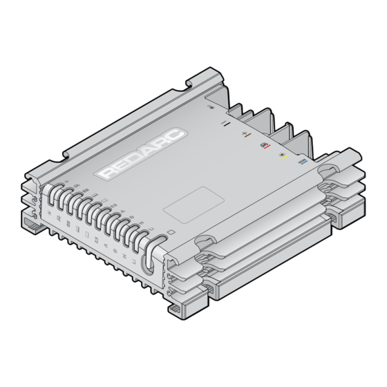
PRODUCT OVERVIEW KIT CONTENTS Terminals Status LEDs Control Button 4× Mounting Points Ref. Part Description Qty. Main Unit Temperature Sensor Cable, 2 m (6'7") M5 × 10 mm Hex Head Phillips Screw M3 × 8 mm Hex Head Phillips Screw Product Overview | 5... -
Page 6: Status Leds
STATUS LEDS The Status LEDs on the Main Unit display the status of the system and its settings. VEHICLE AND SOLAR LEDS Solar The Solar and Vehicle LEDs illuminate when the corresponding input is in use. Input from solar is prioritised to lighten the load on your vehicle's alternator Vehicle and maximise the collection of free solar energy. -
Page 7: Control Button
The Control Button controls the BCDC Alpha and can be used to configure the essential settings. Note that there are additional settings that can be configured using the REDARC Configurator App (see page 23). To wake up the BCDC Alpha, press and hold the Control Button until it turns blue. Press the Control Button again to cycle to the next setting, which is indicated by the LED colour. -
Page 8: Typical Bcdc Alpha Setup
TYPICAL BCDC ALPHA SETUP WIRING DIAGRAM This wiring diagram shows a typical system configuration. If unsure, contact REDARC Technical Support for advice on your individual system requirements. TEMPERATURE SENSOR max. 1.5 m (4'11") GROUND Common Ground* AUXILIARY BATTERY 12 V Auxiliary... -
Page 9: System Planning
SYSTEM PLANNING WHAT YOU WILL NEED TOOLS The tools listed may be required for mounting and wiring the BCDC Alpha: Screwdriver set Power drill Lug/Ring terminal crimping tool ƒ ƒ ƒ Spanner set Side / Cable cutters Heat gun ƒ ƒ ƒ... -
Page 10: Cable And Fuse Sizing
CABLE AND FUSE SIZING CAUTION: Cable sizes are specified by various codes and standards which depend on the type of vehicle the auxiliary battery is installed in. Selecting the wrong cable size could result in harm to the installer or user and/ or damage the BCDC Alpha or other equipment installed in the system. - Page 11 *2 Vehicles with smart alternators may have a reduced charging current if the minimum specified cable gauge is selected for long cable lengths. To avoid this, you can use the next cable size up. Fuses must be mounted within 150 mm (6") of the battery positive (+) terminal — the REDARC KIT19 battery‑to‑fuse cable is recommended for this connection.
-
Page 12: Installation - Mounting
INSTALLATION — MOUNTING MOUNTING REQUIREMENTS The Main Unit can be installed in the engine bay of a vehicle, along a chassis rail or in the cabin of a vehicle. Confirm that all cables can comfortably reach the components in your setup, trimming as needed to avoid ƒ... -
Page 13: Mounting Hardware
MOUNTING ACCESSORIES REDARC has mounting brackets designed for specific vehicle models. They allow you to quickly mount the BCDC Alpha to existing mounting points in your vehicle. Visit the REDARC website to see the full range. MOUNTING STEPS CAUTION: Use suitable Personal Protective Equipment (PPE) when operating power tools. -
Page 14: Installation - Wiring
INSTALLATION — WIRING WARNING: Before beginning wiring, carefully read and follow all advice listed in "Warnings & Safety Instructions" (page 4). CAUTION: Wiring must be installed in protected areas away from heat sources and sharp objects. Cables must not be routed over or through moving parts of the vehicle. Additional protection such as conduit may be required, especially if routing cables through the engine bay and exposed areas. -
Page 15: Connect Cables To The Main Unit
LUG AND HEATSHRINK ASSEMBLY Assemble each cable with the appropriate sized lug using heatshrink as shown. 1. Slide the heatshrink over the cable. 2. Strip the end of the cable back enough to ensure the insulation does not enter the barrel of the lug when fully inserted. 3. -
Page 16: Battery Temperature Sensor Cable Connection
The Battery Temperature Sensor cable allows BCDC Alpha to monitor the temperature of the auxiliary battery during the charging process. BCDC Alpha will then adjust the charging rate automatically to protect against overheating for faster and safer charging. Connect the Temperature Sensor Cable to the negative (–) terminal on the auxiliary battery. -
Page 17: Ground Cable Connection
GROUND CABLE CONNECTION The Ground cable must be connected to a ground point that forms a common ground with all devices in your system. Do this by connecting all grounds to the vehicle chassis or by connecting all grounds to a common ground busbar, (see "Using a Common Ground Busbar"... -
Page 18: Auxiliary Battery Connection
Ensure the cable length is no more than 1.5 m (4'11"). 3. Connect a short cable between the fuse holder and the positive (+) terminal on the auxiliary battery. The short cable must be no longer than 150 mm (6"). REDARC KIT19 is recommended for this connection. 12 V Auxiliary... -
Page 19: Solar Cable Connection
NOTICE: DO NOT connect solar panels that have inbuilt regulators or use a supplementary external regulator. The BCDC Alpha has an inbuilt MPPT regulator that may not function correctly if regulated solar panels are connected. The BCDC Alpha prioritises charging from solar to lighten the load on your vehicle's alternator and maximise the collection of free solar energy. - Page 20 ƒ The total rated power is below the maximum array size (page 36) rating of the BCDC Alpha. All solar panels are the same. ƒ When connecting multiple solar strings in parallel each string must have the same number of solar panels.
- Page 21 Main Unit. Busbars and fuse holders must be suitable for the environmental conditions of their mounting locations. ƒ 4 Solar Strings in Parallel Example (BCDC12050B only) BCDC Alpha 50 BCDC12050B Solar panels e.g. SMRP1120 (120 W ×8)
-
Page 22: Fuse Connections
FUSE CONNECTIONS To complete the Auxiliary Battery cable connection, install and secure the auxiliary battery MIDI fuse to the fuse holder as illustrated below. Then, install and secure the start battery MIDI fuse to the fuse holder to complete the Start Battery cable connection. Auxiliary Battery Fuse Example 12 V Auxiliary Chassis... -
Page 23: System Configuration
5 seconds to indicate that the BCDC Alpha is On and ready to be configured. PAIR TO THE CONFIGURATOR APP Get the RedVision Configurator App ® Download the free REDARC RedVision Configurator App to Configure the settings ® of the BCDC Alpha using your smartphone via Bluetooth ®... -
Page 24: Configure Your Bcdc Alpha Via The App
CONFIGURE YOUR BCDC ALPHA VIA THE APP 1. In the Configurator App, configure the settings listed below to suit your auxiliary battery's specifications. Note, some settings can also be configured via the Control Button on the Main Unit . BCDC Settings: Vehicle Input Trigger (page 25) ƒ... -
Page 25: Set The Vehicle Input Trigger
SET THE VEHICLE INPUT TRIGGER The Vehicle Input Trigger sets the vehicle start battery turn on/off voltage. Configuration: App only Default: Auto Settings: Auto — automatically detects if the start battery is 12 V or 24 V and operates within the 12 / 24 V ƒ... -
Page 26: Set The Maximum Charge Currents
The Max Charge Current sets the maximum current supplied from the BCDC Alpha to be at or below the maximum output of your BCDC Alpha (25 A or 50 A). Ensure the Auxiliary Battery cable size and fuse size installed is capable of carrying this configuration. -
Page 27: Set The Start Battery Charge Mode
Enabled, Disabled When in this Mode, the BCDC Alpha delivers up to 25 A to the start battery (unless the Vehicle Input Current Limit or Max Charge Current is configured lower) and aims to keep the start battery topped up to 12.8 V. -
Page 28: Set The Battery Type
SET THE BATTERY TYPE The Battery Type setting must match the chemistry of your auxiliary battery (refer to the manufacturer’s specifications). It makes sure that the correct charging profile is used for your battery's chemistry type. Configure via: App or Control Button Settings: Control Button Setting App Setting... -
Page 29: Operation
OPERATION PAIR TO THE REDVISION ® Get the RedVision ® The RedVision App gives you remote access to the BCDC Alpha's functions and ® features including system and input source monitoring. PAIRING INSTRUCTIONS 1. Download the RedVision App and make sure Bluetooth is enabled on your smartphone. -
Page 30: Charging Stages
CHARGING STAGES The auxiliary battery's charging stage is indicated by the Charging Stage LEDs on the Main Unit. BOOST Float When the Main Unit is on and charging, it will begin in the Boost stage. This stage gradually ramps up then maintains a constant current until the auxiliary battery's voltage reaches its Absorption voltage. -
Page 31: Start Battery Recovery
When in this Mode, the BCDC Alpha delivers 25 A to the start battery (unless the Vehicle Input Current Limit or Max Charge Current is configured lower) and aims to charge the start battery up to 14.6 V. -
Page 32: Care And Maintenance
CARE AND MAINTENANCE CAUTION: Before performing work or maintenance on the auxiliary electrical system (which includes the Vehicle Start Battery, Auxiliary Battery, and Solar Panels), isolate all input and output sources of power to the electrical system and charger. Isolate the system by removing fuses or by activating isolation switches (if fitted). There is a risk electric shock and fire if all sources of power are not completely isolated before carrying out work. - Page 33 Charger Over Temperature — The Main Unit is above the operating temperature range, see page 36. Disconnect wiring from the Main Unit and wait for it to cool down before using. Internal Hardware Fault — Power cycle the BCDC Alpha by disconnecting all powered terminals, if the fault persists, contact technical support.
-
Page 34: Communication Troubleshooting
Control Button will flash blue rapidly for 1 second to indicate that all device pairings have been cleared. 5. Re‑pair your smartphone and Main Unit by following the bluetooth pairing instructions on page 29. If the fault remains, it is likely an Internal Hardware Fault. Contact REDARC Tech Support. 34 | Care and Maintenance... -
Page 35: Specifications
SPECIFICATIONS GENERAL SPECIFICATIONS BCDC12025B BCDC12050B Weight 925 g (32.6 oz) 960 g (33.9 oz) Dimensions 164 × 146 × 44 mm (6.46" × 5.75" × 1.73") M5 Terminal Depth 9 mm (0.35") M5 Terminal Torque 4 N∙m (2.95 ft∙lbf) M3 Terminal Depth 8 mm (0.31") M3 Terminal Torque 1 N∙m (0.74 ft∙lbf) -
Page 36: Electrical Specifications
ELECTRICAL SPECIFICATIONS BCDC12025B BCDC12050B Nominal Current Rating 25 A 50 A Operating Temperature*¹ –40°C to 85°C (–40°F to 185°F) Start Battery Input 9 to 32 V DC ⎓ Voltage Range Maximum Input Current 28 A 55 A Solar Input 9 to 48 V DC ⎓ Voltage Range*²... -
Page 37: Temperature Compensation
TEMPERATURE COMPENSATION Battery Type Setting Voltage / Temperature Range AGM /Calcium / Gel / SLA 0°C < –30 mV / °C < 60°C (32°F < –17 mV / °F < 140°F) LiFePO 40°C < –70 mV / °C < 60°C (104°F < –39 mV / °F < 140°F) COMPLIANCE AND STANDARDS Compliance Marks IP Rating... -
Page 38: Warranty
WARRANTY For full warranty terms and conditions, visit the Warranty page of the REDARC website: www.redarcelectronics.com/warranty Australia, New Zealand, UK & Europe North America REDARC Electronics Pty Ltd, 23 Brodie Road (North), REDARC Corporation, c/o Shallco, Inc., 308 Lonsdale SA 5160, Australia Component Dr., Smithfield, NC 27577, USA... - Page 39 REDARC®, THE POWER OF REDARC®, RedVision®, BCDC® and BCDC Alpha® are trademarks of Redarc Electronics Pty Ltd. | The Bluetooth® word mark and logos are registered trademarks owned by Bluetooth SIG, Inc. and any use of such marks by REDARC is under license. | Other trademarks and trade names are those...
- Page 40 Tech Support 1300 REDARC (1300‑733‑272) Australia +61 8 8322 4848 New Zealand +64 9 222 1024 UK & Europe +44 (0)20 3930 8109 +1 (704) 247‑5150 Canada +1 (604) 260‑5512 Mexico +52 (558) 526‑2898 redarcelectronics.com INST300‑1...
Need help?
Do you have a question about the BCDC ALPHA and is the answer not in the manual?
Questions and answers