Table of Contents
Advertisement
Quick Links
Advertisement
Table of Contents

Related Manuals for RuggON PX501C8H


Summary of Contents for RuggON PX501C8H
- Page 1 PX501 Gen III User's Manual...
- Page 2 ©2018 RuggON Corporation. All rights reserved. TRADEMARKS RuggON logo is a trademark of RuggON Corporation, registered in the United States Patent and Trademark Office and in other countries. Microsoft and the Windows logo are either registered trademarks or trademarks of Microsoft Corporation in the United States and/or other countries.
-
Page 3: Table Of Contents
Table of Contents About This Manual Related Information ..................1 Conventions ....................1 Basic Safety Guidelines Intended Use ....................2 Maintenance and Operation Overview ............2 Safety ......................3 Electrical Hazards ..................3 Environmental ..................... 3 Radio Transmissions ................... 4 Cleaning and Servicing ................ - Page 4 Overview ....................48 Chapter 6. Troubleshooting Troubleshoot the Wi-Fi Connection ............50 Troubleshoot Operating the Computer ............51 Call Product Support ................. 51 Chapter 7. Maintenance Cleaning the Device .................. 52 Returning the Device ................. 52 Contacting RuggON .................. 52...
-
Page 5: About This Manual
Related Information Current information and manuals are available for download at the following website: http://www.ruggon.com Conventions Bolded or underlined text is used to emphasize the designated information. A Note is used to provide additional information for the device or settings. -
Page 6: Basic Safety Guidelines
Basic Safety Guidelines The following safety guidelines are intended to help protect the user from injury and prevent damage to the hardware. ■ Do not place anything on the AC adapters power cable and make sure the cable is not located where it can be tripped over or stepped on. -
Page 7: Safety
Use only Supplied Power Cables RuggON power cables meet industrial requirements for low-temperature flexibility, UV resistance, and oil resistance. Use only supplied power cables from RuggON. -
Page 8: Radio Transmissions
Radio Transmissions Permitted Transmission Power Follow the national regulations for the maximum permitted transmission power. The operator is solely responsible for this type of operation. Radio Frequency Limited Locations Considering the radio frequency limitation in hospitals and aircraft, the PX501 can only be installed with permission. -
Page 9: Lithium Battery Safety Statement
Labeling Requirements This device complies with Part 15 of the FCC Rules. Operation is subject to the following two conditions: (1) this device may not cause harmful interference, and (2) this device must accept any interference received, including interference that may cause undesired operation. RF Exposure Information (SAR) This device meets the government¡s requirements for exposure to radio waves. -
Page 10: Chapter 1. Introduction
Unpacking the Device Before you begin the installation or configuration process make sure to inspect all components and accessories. Contact your representative if there are any missing or damaged items. See “Contacting RuggON” on page 52. Technical Specifications Table 1. Technical Specifications... - Page 11 Introduction Item Description Wireless WLAN Wi-Fi IEEE 802.11 a/b/g/n/ac Bluetooth Bluetooth V4.2 WWAN (Optional) Option 4G LTE Sensor Sensor Gyroscope, G Sensor, E-compass, Light Sensor Docking Connector 12-pin DC-IN Jack Micro SIM Card Slot Audio Jack x1; headphone / microphone combo USB 3.01 x2;...
-
Page 12: Px501 Configuration Options
Introduction Item Description Rugged Specifications Drop 153 cm (5 feet), 26 drops on plywood ■ Vibration (MIL-STD-810G Method 514.6 Category 4, Fig 514.6C-1, Fig 514.6C-2, Fig 514.6C-3) ■ Drop (MIL-STD-810G Method 516.6 Procedure IV) ■ Mechanical shock MIL-STD 810G (MIL-STD-810G Method 516.6 Procedure I, Procedure V) ■... -
Page 13: Parts List
Introduction Parts List The PX501 is shipped with the following items. All other accessories are sold and ordered separately. For help, contact your local RuggON sales representative. See “Contacting RuggON” on page 52. PX501 Power Adapter Stylus or Digitizer... -
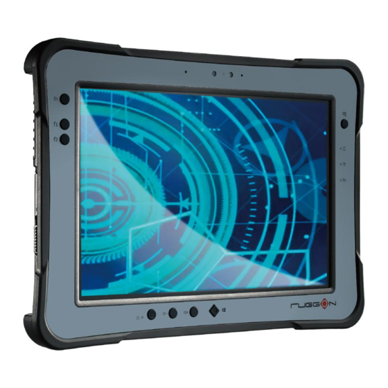
Page 14: Identifying The Device
Introduction Identifying the Device Overview Figure 1. Overview Table 2. Overview Item Description See “Side View” on page 13 for further information. Left view See “Front View” on page 11 for further information. Front view See “Rear View” on page 14 for further information. Rear view See “Side View”... - Page 15 Introduction Front View 11 10 9 8 7 Figure 2. Front View Table 3. Front View Item Description Front camera 2.0 Mega-Pixels camera. Touch screen 5-point capacitive touch. Barcode trigger If barcode scanner is installed, press to scan. Display battery status, see “LED Status” on page 12. Battery LED Wi-Fi LED The Wi-Fi LED lights to indicate Wi-Fi is enabled.
- Page 16 Introduction LED Status Table 4. LED Status Item Status Description Green: On Power on Power Power off Green: On Fully charged Amber: On Charging Battery Amber: Low power < 15% Blinking Not charging / no battery Blue: On FN function switch on Blue: Off FN function switch off Blue: On...
- Page 17 Introduction Side View Left view Right view Figure 4. Side Views Table 6. Side View Item Description Micro HDMI Connect HDMI devices to the PX501. USB 3.1 Type C Connect USB devices to the PX501. Left I/O Open to access the left I/O port. compartment cover Tether hole...
-
Page 18: Identifying The Digitizer
Introduction Rear View Figure 5. Rear View Table 7. Rear View Item Description Battery To install a battery, an external battery is optional. Rear camera 8.0 Mega-Pixels camera with LED auxiliary light. Barcode reader For installing a barcode reader. (Optional) Embedded fan for cooling. -
Page 19: Dimensions
Introduction Dimensions The following image lists the device dimensions without add-ons (mm/inches). 280 / 11 28 / 11 Figure 7. Front View Dimensions 23 / 0.9 2.3 / 0.9 Figure 8. Side View Dimensions... -
Page 20: Touch Screen Features
Introduction Touch Screen Features Always use the point of the digitizer for clicking or making strokes on the touch screen. Never use an actual pen, pencil, or sharp/abrasive object on the touch screen. The digitizer is used as if it were a pen or pencil. Touch the screen with the tip of the digitizer then remove the digitizer from the screen. -
Page 21: Chapter 2. Getting Started
This section provides an outline of the steps necessary to setup a new PX501. A detailed guide follows the listed items, see as follows. For additional technical assistance, contact your RuggON representative. See “Contacting RuggON” on page 52. It is recommended to installing or remove accessories on a clean, well-lit work surface. -
Page 22: Powering The Device On And Off
Getting Started Connect the AC adapter to the DC-IN port. Figure 10. Connecting the AC Adapter After charging the battery, disconnect the AC adapter and close the DC-IN cover. Insert one end of the cover first and angle the cover to seat it in place. Push in the cover to seal the DC-IN compartment. -
Page 23: Installing The Micro Sim Card
Getting Started Powering Off the Device ■ Start screen: > Shut down. ■ Desktop screen: Tap and hold at the bottom left corner of the Desktop screen. Tap Shut down or sign out > Shut down. ■ Bot h Start screen and Desktop screen: Display charm bar and tap Settings. -
Page 24: Using The Digitizer
Getting Started Take the micro SIM card from its packaging. Push the SIM card cover to open and place the micro SIM card to the slot. Close the SIM card cover. Figure 15. Installing the Micro SIM Card Install the 4G LTE card and its antennas to the slot and close the service door. Using the Digitizer Following the information below when using a digitizer: ■... -
Page 25: Removing The Protective Film From The Display
Getting Started Removing the Protective Film from the Display The front display of the PX501 is protected during transport by a transparent film. This film should remain on the front display during assembly to avoid damage to the front display surface. Only remove the film once all of the assembly work has been completed. -
Page 26: Chapter 3. Operation
Operation Chapter 3. Operation Opening the I/O Compartment Cover Place the device display side down on a clean work surface. Locate the I/O compartment cover. Right view Left view Right I/O Compartment Cover Left I/O Compartment Cover Figure 17. Side View: Locating the I/O Compartment Cover Unlock the latch. -
Page 27: Closing The I/O Compartment Cover
Operation Closing the I/O Compartment Cover Place the device display side down on a clean work surface. Locate the I/O compartment cover. Left view Right view Right I/O Compartment Cover Left I/O Compartment Cover Figure 20. Side View: Locating the I/O Compartment Cover Flip the I/O compartment cover and install. -
Page 28: Connecting To External Cabling
Operation Connecting to External Cabling To prevent damage to the device, connect all cabling and accessories before powering up the device. Connect USB Cabling The PX501 have one USB 3.1 Type C and one USB 3.1 Type A port for connecting USB devices, such as a digital camera, scanner, printer, modem, and mouse. - Page 29 Operation Connect Audio Cabling For higher audio quality, you can send sound through external audio devices such as speakers, headphones, or earphone using audio connector. Open the left I/O compartment cover. See “Opening the I/O Compartment Cover” on page Connect the audio cable. Figure 25.
-
Page 30: Handstrap, Carrying Handle And Shoulder Strap
Operation Connect RS-232 Cabling Connect to RS-232 devices with an RS-232 cable. Open the right I/O compartment cover. See “Opening the I/O Compartment Cover” on page Align the RS-232 cable with the port in the device and connect it. Turn the locking screws on the cable to secure it to the device. Figure 27. - Page 31 Operation Install the D-rings. Make sure the D-rings are tightly secured before installing the handstrap. Figure 29. Installing the D-rings Connect the handstrap on the D-rings. When the handstrap is installed, the digitizer can be placed under the strap. Figure 30. Connecting the Handstrap...
- Page 32 Operation Removing the Handstrap Unlock the handstrap from the D-rings. Figure 31. Removing the Handstrap Remove the D-rings. Figure 32. Removing the D-rings Secure the bumper and the PX501 with screws. Figure 33. Securing the Screws...
- Page 33 Operation Connecting the Carrying Handle Attach the clips to the D-rings. Figure 34. Connecting the Carrying Handle Removing the Carrying Handle Press in the clips to release them from the D-rings. Remove the clips. Figure 35. Removing the Carrying Handle Connecting the Shoulder Strap Attach the clips to the D-rings.
-
Page 34: Installing The Standard Battery
Operation Removing the Shoulder Strap Press in the clips to release them from the D-rings. Remove the clips. Figure 37. Removing the Shoulder Strap Installing the Standard Battery The following instructions are for both standard and external batteries. The external battery is an optional component. -
Page 35: Removing The Standard Battery
Operation Align the tabs on the battery with the slots on the chassis. Angle the battery in place and set the tabs in the chassis slots. Lower the raised end of the battery and press in place until an audible click is heard. Figure 39. - Page 36 Operation Slide the locking switch on the top-left side to the unlock position. Figure 42. Unlock the Battery Press and hold the release button as shown in the image to release the battery. Hold the battery and angle the left side up to remove. Figure 43.
-
Page 37: Connecting To A Wireless Network
Operation Connecting to a Wireless Network Before you can make use of the PX501 wireless functions, you need to connect to a network. The following is a set of procedures for connecting to a wireless network. Before beginning, make sure your Wi-Fi setting is enabled and you are within range of a wireless network. -
Page 38: Chapter 4. Using Bios Setup Utility
Using BIOS Setup Utility Chapter 4. Using BIOS Setup Utility Your ruggedized tablet has a BIOS setup utility which allows you to configure important system settings, including settings for the Boot and AP menus as well as the device’s basic settings--the system reads the basic settings during initialization in order to boot correctly When to Use the BIOS Setup Utility You need to run the BIOS Setup utility when:... -
Page 39: Installation An Operating System
Using BIOS Setup Utility Due to the device’s fast boot up and boot down time, there is only a small time frame of a few seconds between the release of the Power button and the opportunity to press the Windows Home key. - Page 40 Using BIOS Setup Utility Tap Yes to enable CSM support. Figure 46. Main > Boot Features ■ Step 2 Enable Legacy Boot Access the BIOS Setup Utility, see “Accessing the BIOS Setup Utility” on page 34. Navigate to APP Menu > Main > Boot Features. Locate the Legacy Boot setting and tap on the menu to select On enable legacy boot.
- Page 41 Using BIOS Setup Utility Navigate to APP Menu > Exit and tap Exit Saving Changes. Figure 48. Exit the BIOS Utility A prompt display, tap Yes to save the configuration. The BIOS settings are configured and the Windows 7 operating system can be installed.
-
Page 42: Bios Passwords
Using BIOS Setup Utility BIOS Passwords Setting Up a Supervisor Password To setup a supervisor password, follow the procedure as described: Go to APP Menu > Security > Account’s Password Status. Tap the Enter icon next to Setup the Supervisor Password to access the virtual keyboard. Figure 49. - Page 43 Using BIOS Setup Utility Verification of the password is required. Tap the same password again and tap Enter to confirm the new password. Navigate to APP Menu > Exit. Figure 51. Exit Screen Tap Exit Saving Changes to display the confirmation screen. Tap Yes to save the new configuration settings.
-
Page 44: Ec And Bios
Using BIOS Setup Utility EC and BIOS Updating BIOS This procedure allows you to update and re-flash the system BIOS. Both procedures follow the same steps as described in the following. Make sure to protect your device from power loss during the BIOS update procedure to prevent irreparable damage to your system’s mainboard. - Page 45 Using BIOS Setup Utility Tap Update & Security. Figure 53. Update & Security From the Update & Security screen, tap Recovery, then tap Restart now Figure 54. Recovery...
- Page 46 Using BIOS Setup Utility Tap Use a device to select a boot up preference. Figure 55. Use a Device From the Use a device menu, tap Internal Shell to open the command screen. Make sure connect the PX501 to the AC adapter to prevent a sudden loss of power. Figure 56.
- Page 47 Using BIOS Setup Utility 10. In the command screen, enter fs1: to select the USB device already connected to the device. The command directs you to the USB device’s root menu. Figure 57. Internal Shell Command Screen 11. If the BIOS file is in a folder and not in the root directory, navigate to the target folder. 12.
-
Page 48: Chapter 5. Using The Dashon Utility
DashON menus. Important: Do not terminate or remove the DashON program manually or the ambient light sensor and the function buttons will be malfunction. Download the latest information and documentation through the RuggON official site: http://www.ruggon.com/ Figure 58. DashON Overview... - Page 49 Using the DashON Utility Function Description Touch Screen Lock Lock or unlock the touch screen. Disable or enable ECO mode to save battery life when using the ECO Mode device. Power Plan Manage how your tablet uses power. Info Viewer View system specifications.
-
Page 50: Chapter 6. Troubleshooting
If you send the computer in for service, it is your responsibility to save the computer data and configuration. RuggON is responsible only for ensuring that the hardware matches the original configuration when repairing or replacing the computer. -
Page 51: Troubleshoot Operating The Computer
The computer appears to be locked up and you cannot enter data. Restart the computer. Call Product Support Simple instructions please contact the dealer, contact ruggon representative, or leave a message visit the RuggON website at www.ruggon.com. To better assist you have the following information ready: ■... -
Page 52: Chapter 7. Maintenance
Prevent using any kind of chemical solvent, acidic or alkali solution. Returning the Device Please put the contents in the original package gently when you need to return the PX501. Contacting RuggON If you experience technical difficulties, please consult your distributor or contact the technical services department:...
Need help?
Do you have a question about the PX501C8H and is the answer not in the manual?
Questions and answers