Table of Contents
Advertisement
Advertisement
Table of Contents

Related Manuals for RuggON PX-501


Summary of Contents for RuggON PX-501
- Page 1 PX-501 User's Manual...
- Page 2 ©2015 RuggON Corporation. All rights reserved. TRADEMARKS RuggON logo is a trademark of RuggON Corporation, registered in the United States Patent and Trademark Office and in other countries. Microsoft and the Windows logo are either registered trademarks or trademarks of Microsoft Corporation in the United States and/or other countries.
-
Page 3: Table Of Contents
Lithium Battery Safety Statement ..............5 Chapter 1. Introduction About This Guide ..................7 Unpacking the Device ...................7 Technical Specifications ................7 PX-501 Configuration Options ..............9 Parts List .....................10 Identifying the Device ................. 11 Identifying the Digitizer ................15 Dimensions ....................16 Touch Screen Features ................17 Chapter 2. - Page 4 EC and BIOS ....................44 Chapter 5. Using the DashON Utility Overview .....................49 Chapter 6. Troubleshooting Troubleshoot the Wi-Fi Connection ............62 Troubleshoot Operating the Computer ............63 Call Product Support ..................63 Chapter 7. Maintenance Cleaning the Device ...................64 Returning the Device ..................64 Contacting RuggON ...................64...
-
Page 5: About This Manual
About This Manual The PX-501 User’s Manual provides instruction for qualified personnel to follow when setting up a new PX-501 device. This document is intended for use by qualified personnel to compliment the training and expertise, not to replace it. -
Page 6: Basic Safety Guidelines
The PX-501 is designed and manufactured according to strict controls and following the stated safety regulations. The following list identifies incorrect operating uses of the PX-501. Incorrect use of the PX-501 can lead to hardware damage, safety issues and possible risk to personnel health: „... -
Page 7: Safety
Environmental Ambient Temperature The PX-501 operates on the basis of a passive cooling concept which internal waste heat is released via the housing surface and requires fresh airflow in the environment. „ Operating the PX-501 with no fresh cooling air may cause overheating and damage to the device. -
Page 8: Radio Transmissions
The operator is solely responsible for this type of operation. Radio Frequency Limited Locations Considering the radio frequency limitation in hospitals and aircraft, the PX-501 can only be installed with permission. Industrial computers may affect the function of implanted medical devices such as pacemakers and may cause malfunction. -
Page 9: Lithium Battery Safety Statement
„ Consult the dealer or an experienced radio / TV technician for help. Any changes or modifications not expressly approved by the grantee of this device could void the user’s authority to operate the equipment. This device is operation in 5.15 – 5.25GHz frequency range, then restricted in indoor use only, Outdoor operations in the 5.15 –... -
Page 11: Chapter 1. Introduction
Embedded Standard 8 64bits About This Guide The PX-501 User Manual provides instruction for qualified personnel to use as a guide for setup of the device. This document is not intended to replace the training and expertise of the end-user. - Page 12 Introduction Item Description Wireless WLAN Wi-Fi IEEE 802.11 a/b/g/n/ac Bluetooth Bluetooth V4.0 WWAN (Optional) Option for 3.5G or 4G LTE Sensor Sensor Gyroscope, G Sensor, E-compass, Light Sensor Docking Connector 12-pin DC-IN Jack Micro SIM Card Slot MicroSD Slot Audio Jack x1;...
-
Page 13: Px-501 Configuration Options
-20°C (-4°F) to 60°C (140°F) Range Storage Temperature -30°C (-22°F) to 70°C (158°F) Range Humidity 5-95% without condensation PX-501 Configuration Options The following options are available for the PX-501: „ NFC module „ Barcode reader „ Smart card reader „... -
Page 14: Parts List
Introduction Parts List The PX-501 is shipped with the following items. All other accessories are sold and ordered separately. For help, contact your local RuggON sales representative. See “Contacting RuggON” on page 64. PX-501 Power Adapter Digitizer 2-Point Carrying Handle... -
Page 15: Identifying The Device
Introduction Identifying the Device Overview Figure 1. Overview Table 2. Overview Item Description See “Side View” on page 14 for further information. Left view See “Front View” on page 12 for further information. Front view See “Rear View” on page 15 for further information. Rear view See “Side View”... -
Page 16: Front View
8 home key. ® Volume + Volume increase. Volume - Volume decrease. Power key Turns the PX-501 on or off. Power LED The power LED lights when the device is on. F2 key Programmable function key. F1 key Programmable function key. -
Page 17: Bottom View
Bottom View Figure 3. Bottom View Table 5. Bottom View Item Description Docking connector 12 pin connector for docking onto a station. Kensington lock Lock the PX-501 to a stationary object for security. Pass-through Dual pass-through for WLAN, GNSS and WWAN. -
Page 18: Side View
Connect USB devices to the PX-501. Audio jack Connect a 3.5 mm jack for a headphone or external speakers. Ethernet Connect the PX-501 to an Ethernet (RJ-45) cable. DC-IN jack Insert power connector to charge battery. RS-232 Connect the PX-501 to a serial device. -
Page 19: Identifying The Digitizer
Digitizer holder Place digitizer here. Identifying the Digitizer You can use the digitizer to control your PX-501 as with a mouse or keyboard. The digitizer is not waterproof. Take care not to soak it or dip it in water. Click Button... -
Page 20: Dimensions
Introduction Dimensions The following image lists the device dimensions without add-ons (mm/inches). 280 / 11 28 / 11 Figure 7. Front View Dimensions 23 / 0.9 2.3 / 0.9 Figure 8. Side View Dimensions... -
Page 21: Touch Screen Features
Introduction Touch Screen Features Always use the point of the digitizer for clicking or making strokes on the touch screen. Never use an actual pen, pencil, or sharp/abrasive object on the touch screen. The digitizer is used as if it were a pen or pencil. Touch the screen with the tip of the digitizer then remove the digitizer from the screen. -
Page 22: Chapter 2. Getting Started
Close the left I/O compartment cover. See “Closing the I/O Compartment Cover” on page Charging the Battery When you use the AC adapter to connect your PX-501 to a power outlet, the standard and external (optional) battery will automatically begin to recharge. -
Page 23: Powering The Device On And Off
Powering the Device On and Off Powering On the Device Only power on the PX-501 after connecting all of the peripherals and cabling. Press and hold the power button until the screen lights. The device runs through the start up sequence and powers up. -
Page 24: Installing The Micro Sim Card
Check with your network or cellular service provider for availability and cost rates. Power off the PX-501. See “Powering Off the Device” on page 20. Open the left I/O compartment cover. See “Opening the I/O Compartment Cover” on page Locate the micro SIM slot in the left I/O parts. -
Page 25: Removing The Micro Sim Card
Close the left I/O compartment cover. See “Closing the I/O Compartment Cover” on page Removing the Micro SIM Card Power off the PX-501. See “Powering Off the Device” on page 20. Open the left I/O compartment cover. See “Opening the I/O Compartment Cover” on page Locate the micro SIM slot in the left I/O parts. -
Page 26: Installing The Microsd Card
Getting Started Press the micro SIM card in and release it. The card springs out. Grasp the micro SIM card and remove it from the slot. Figure 17. Removing the Micro SIM Card Close the left I/O compartment cover. See “Closing the I/O Compartment Cover” on page Installing the MicroSD Card The device supports microSD card for easier data storage. -
Page 27: Removing The Microsd Card
Getting Started The microSD card has a beveled edge. Align the microSD card with the slot making sure that the corners match. Insert the microSD card and press it in until an audible click sounds. Figure 19. Installing the MicroSD Card Close the left I/O compartment cover. -
Page 28: Using The Digitizer
Getting Started Press the microSD card in and release it. The card springs out. Grasp the microSD card and remove it from the slot. Figure 21. Removing the MicroSD Card Close the left I/O compartment cover. See “Closing the I/O Compartment Cover” on page Using the Digitizer Following the information below when using a digitizer: „... -
Page 29: Removing The Protective Film From The Display
Getting Started Removing the Protective Film from the Display The front display of the PX-501 is protected during transport by a transparent film. This film should remain on the front display during assembly to avoid damage to the front display surface. -
Page 30: Chapter 3. Operation
Operation Chapter 3. Operation Opening the I/O Compartment Cover Place the device display side down on a clean work surface. Locate the I/O compartment cover. Left view Right view Right I/O Compartment Cover Left I/O Compartment Cover Figure 23. Side View: Locating the I/O Compartment Cover Unlock the latch. -
Page 31: Closing The I/O Compartment Cover
Operation Closing the I/O Compartment Cover Place the device display side down on a clean work surface. Locate the I/O compartment cover. Left view Right view Right I/O Compartment Cover Left I/O Compartment Cover Figure 26. Side View: Locating the I/O Compartment Cover Flip the I/O compartment cover and install. -
Page 32: Connecting To External Cabling
Connect USB Cabling The PX-501 have one USB port for connecting USB devices, such as a digital camera, scanner, printer, modem, and mouse. The USB port support USB 2.0 or USB 3.0 devices. Open the left I/O compartment cover. See “Opening the I/O Compartment Cover” on page Connect to USB device via USB cable. - Page 33 Connect Micro HDMI Cabling Connect to HDMI devices via micro HDMI cable. Open the left I/O compartment cover. See “Opening the I/O Compartment Cover” on page Connect micro HDMI cable to micro HDMI port on the PX-501. Figure 32. Connect Micro HDMI Cabling...
-
Page 34: Handstrap, Carrying Handle And Shoulder Strap
Figure 33. Connect RS-232 Cabling Handstrap, Carrying Handle and Shoulder Strap The PX-501 is equipped with a handstrap, a carrying handle and a shoulder strap for convenience and choice. Select the accessory that is right for your needs. The handstrap can be installed with either the shoulder strap or the carrying handle. However, the handle and shoulder strap can not be installed together due to space constraints. - Page 35 Operation Install the D-rings. Make sure the D-rings are tightly secured before installing the handstrap. Figure 35. Installing the D-rings Connect the handstrap on the D-rings. When the handstrap is installed, the digitizer can be placed under the strap. Figure 36. Connecting the Handstrap...
- Page 36 Operation Removing the Handstrap Unlock the handstrap from the D-rings. Figure 37. Removing the Handstrap Remove the D-rings. Figure 38. Removing the D-rings Secure the bumper and the PX-501 with screws. Figure 39. Securing the Screws...
- Page 37 Operation Connecting the Carrying Handle Attach the clips to the metal loop on the bumper. Metal Loop Figure 40. Connecting the Carrying Handle Removing the Carrying Handle Press in the clips to release them from the metal loop. Remove the clips. Metal Loop Figure 41.
-
Page 38: Installing The Standard Battery
Operation Removing the Shoulder Strap Press in the clips to release them from the metal loop. Remove the clips. Metal Loop Figure 43. Removing the Shoulder Strap Installing the Standard Battery The following instructions are for both standard and external batteries. The external battery is an optional component. -
Page 39: Removing The Standard Battery
Operation Align the tabs on the battery with the slots on the chassis. Angle the battery in place and set the tabs in the chassis slots. Lower the raised end of the battery and press in place until an audible click is heard. Figure 45. -
Page 40: Connecting To A Wireless Network
Figure 49. Removing the Battery Connecting to a Wireless Network Before you can make use of the PX-501 wireless functions, you need to connect to a network. The following is a set of procedures for connecting to a wireless network. - Page 41 Operation Select the network you want to connect to, and tap the Connect button. You can tap the Connect Automatically check box if you connect to this network frequently. If you connect to the network, you are finished with the process. The network is considered an Open unsecured network, no passoword is required.
-
Page 42: Chapter 4. Using Bios Setup Utility
To run the BIOS Setup Utility, use the following procedures: Perform one of the following: „ If the PX-501 is powered off Press the Power button to start up the device. The power LED lights. Quickly press and hold the Windows Home key until the BIOS Post screen displays. -
Page 43: Installation An Operating System
Using BIOS Setup Utility Due to the device’s fast boot up and boot down time, there is only a small time frame of a few seconds between the release of the Power button and the opportunity to press the Windows Home key. - Page 44 Using BIOS Setup Utility Tap Yes to enable CSM support. Figure 52. Main > Boot Features „ Step 2 Enable Legacy Boot Access the BIOS Setup Utility, see “Accessing the BIOS Setup Utility” on page 38. Navigate to APP Menu > Main > Boot Features. Locate the Legacy Boot setting and tap on the menu to select On enable legacy boot.
- Page 45 Using BIOS Setup Utility Navigate to APP Menu > Exit and tap Exit Saving Changes. Figure 54. Exit the BIOS Utility A prompt display, tap Yes to save the configuration. The BIOS settings are configured and the Windows 7 operating system can be installed.
-
Page 46: Bios Passwords
Using BIOS Setup Utility BIOS Passwords Setting Up a Supervisor Password To setup a supervisor password, follow the procedure as described: Go to APP Menu > Security > Account’s Password Status. Tap the Enter icon next to Setup the Supervisor Password to access the virtual keyboard. Figure 55. - Page 47 Using BIOS Setup Utility Verification of the password is required. Tap the same password again and tap Enter to confirm the new password. Navigate to APP Menu > Exit. Figure 57. Exit Screen Tap Exit Saving Changes to display the confirmation screen. Tap Yes to save the new configuration settings.
-
Page 48: Ec And Bios
Contact your technical sales or technical representative to obtain the correct BIOS file. Copy the BIOS file on to the USB device. Connect the USB device to one of the device’s USB ports and power on the PX-501. A USB keyboard is required for entering command. - Page 49 Using BIOS Setup Utility Tap Change PC settings. Figure 59. Change PC Settings From the PC settings menu, tap Update and recovery to continue. Figure 60. Update and Recovery...
- Page 50 Using BIOS Setup Utility From the Update and recovery screen, tap Recovery. The Advanced startup option displays. Figure 61. Recovery Under Advanced startup, tap Restart now. Figure 62. Restart Now...
- Page 51 Figure 63. Use a Device 11. From the Use a device menu, tap Internal Shell to open the command screen. Make sure connect the PX-501 to the AC adapter to prevent a sudden loss of power. Figure 64. Internal Shell...
- Page 52 The BIOS is now updated. Updating EC Connect the PX-501 to the AC adapter to prevent a sudden loss of power. Updating EC requires the use of the Internal Shell Command menu, refer to steps 1 to 12 of “Updating BIOS”.
-
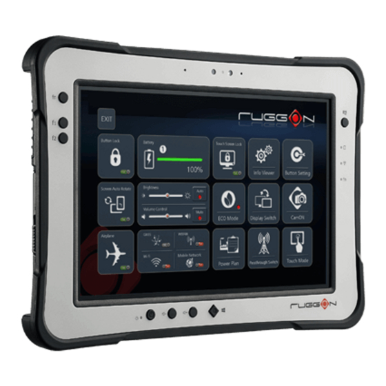
Page 53: Chapter 5. Using The Dashon Utility
Function Description EXIT Close DashON and return to the desktop. Button Lock Lock or unlock the function keys on PX-501. Screen Auto Rotate Disable or enable screen auto rotate function. Airplane Turn on or off the airplane mode. Shows the battery level or charging status. - Page 54 Manage how your PX-501 uses power. Power Plan Note: The function is only available on Windows 7. Info Viewer View PX-501 system specifications. The menu is for display only. Display Switch Choose a display mode when connect to another output device. Pass-through Switch Connect to the pass-through switch.
-
Page 55: Airplane Mode
Using the DashON Utility Screen Auto Rotate The Screen Auto Rotate function disables or enables the auto screen rotation when the device is being rotated. Tap to enable or disable the function. Figure 72. Screen Auto Rotate Airplane Mode The Airplane function disables or enables Airplane Mode. While in Airplane Mode all functions except broadcasting functionality are available. - Page 56 Using the DashON Utility Battery Shows the battery level or charging status. Figure 74. Battery Brightness The Brightness function disables or enables the auto brightness function. Tap to enable or disable the function. The slide bar allows for manual adjustment of the brightness setting. Figure 75.
-
Page 57: Volume Control
Using the DashON Utility Volume Control The Volume Control function disables or enables the mute function. Tap to enable or disable the function. The slide bar allows for manual adjustment of the volume level. Figure 76. Volume Control GNSS The GNSS function disables or enables the Global Navigation Satellite System module. Tap to enable or disable the function. - Page 58 Using the DashON Utility Wi-Fi The Wi-Fi function disables or enables wireless module. Tap to enable or disable the function. Figure 78. Wi-Fi Bluetooth The Bluetooth function disables or enables bluetooth module. Tap to enable or disable the function. Figure 79. Bluetooth...
-
Page 59: Mobile Broadband
Using the DashON Utility Mobile Broadband The Mobile Broadband function disables or enables mobile broadband module. Tap to enable or disable the function. Figure 80. Mobile Broadband Touch Screen Lock The Touch Screen Lock function disables the touch functionality on the screen. Tap to enable or disable the function. - Page 60 Using the DashON Utility To enable touch functionality, tap the Fn key until the Touch Screen Unlocked screen displays. Figure 82. Unlock Touch Screen ECO Mode The ECO Mode provides three states: On, Auto, and Off, to help in battery life management. Figure 83.
-
Page 61: Power Plan
Using the DashON Utility Tap On to enable the mode whenever the device is turned on. Tap Auto to allow the utility to select periods of inactivity to power down. Tap Off to disable the ECO Mode. Tap Cancel to return to the main menu. Figure 84. - Page 62 Using the DashON Utility Modify the On Battery, In Charge, or ECO Mode states to define the power scheme best suited to your needs. To modify the a power plan, tap the drop-down menu of the relevant setting, then tap Save to create the new power plan scheme.
- Page 63 Using the DashON Utility Display Switch The Display Switch function supports four types of display options: „ View desktop on main display „ View desktop on main display and show extended display „ Duplicate both displays „ View desktop on extended display. Figure 88.
- Page 64 Using the DashON Utility Pass-through Switch This function is only available when an antenna pass-through is connected to the port, see “Bottom View” on page 13. GPS, WWAN and Wi-Fi settings are available once the optional RF antenna is connected. Figure 90.
- Page 65 Using the DashON Utility Button Setting The external function buttons are configured with pre-defined commands. However, the buttons can be configured to open any number of executable commands. In combination with the Fn key, the function buttons can trigger up to six different commands. Figure 92.
-
Page 66: Chapter 6. Troubleshooting
If you send the computer in for service, it is your responsibility to save the computer data and configuration. RuggON is responsible only for ensuring that the hardware matches the original configuration when repairing or replacing the computer. -
Page 67: Troubleshoot Operating The Computer
The computer appears to be locked up and you cannot enter data. Restart the computer. Call Product Support Simple instructions please contact the dealer, contact ruggon representative, or leave a message visit the RuggON website at www.ruggon.com. To better assist you have the following information ready: „... -
Page 68: Chapter 7. Maintenance
Maintenance Chapter 7. Maintenance Cleaning the Device Danger to electric shock when cleaning or maintaining the PX-501. To avoid electric shock, turn the PX-501 off and disconnect it from the power supply before cleaning or maintaining it. Housing „ The housing of the PX-501 is best cleaned with a damp cloth.
Need help?
Do you have a question about the PX-501 and is the answer not in the manual?
Questions and answers