Table of Contents
Advertisement
Quick Links
Advertisement
Table of Contents

Related Manuals for RuggON PM-522B4N


Summary of Contents for RuggON PM-522B4N
- Page 1 PM-522 User's Manual...
- Page 3 ©2014 RuggON Corporation. All rights reserved. TRADEMARKS RuggON logo is a trademark of RuggON Corporation, registered in the United States Patent and Trademark Office and in other countries. Microsoft and the Windows logo are either registered trademarks or trademarks of Microsoft Corporation in the United States and/or other countries.
-
Page 5: Table Of Contents
Table of Contents About This Manual Related Information ..................1 Conventions ....................1 Basic Safety Guidelines Intended Use ....................2 Maintenance and Operation Overview ............2 Safety ......................3 Electrical Hazards ..................3 Safety Guidelines for Mounting ..............4 Environmental ....................4 Radio Transmissions ..................4 Cleaning and Servicing .................4 Regulatory and Certification .................5 Lithium Battery Safety Statement ..............6 Chapter 1. - Page 6 Removing the Micro SIM Card ..............24 Removing the I/O Cover ................24 Replacing the I/O Cover ................25 Connecting to External Cabling ..............26 Handstrap and Shoulder Strap ..............28 Charging the Battery ...................34 Installing the External Battery ..............35 Removing the External Battery ..............38 Installing the Barcode Scanner (Optional) ..........41 Removing the Barcode Scanner (Optional) ..........44 Installing the Mag Strip Reader (Optional) ..........45...
- Page 7 Chapter 6. Maintenance Cleaning the Device ...................72 Returning the Device ..................72 Contacting RuggON ...................72...
-
Page 9: About This Manual
Related Information Current information and manuals are available for download at the following website: http://www.ruggon.com Conventions Bolded or underlined text is used to emphasize the designated information. A Note is used to provide additional information for the device or settings. -
Page 10: Basic Safety Guidelines
Basic Safety Guidelines The following safety guidelines are intended to help protect the user from injury and prevent damage to the hardware. Do not place anything on the AC adapters power cable and make sure the cable is not „ located where it can be tripped over or stepped on. -
Page 11: Safety
Ensure that the power cable is laid properly and properly secured. „ Use only Supplied Power Cables RuggON power cables meet industrial requirements for low-temperature flexibility, UV resistance, and oil resistance. Use only supplied power cables from RuggON. If other power cables are used, the following may apply: The operator is solely responsible for the resulting damage;... -
Page 12: Safety Guidelines For Mounting
USB devices. Only Use Authorized Accessories Only use the supplied cables, power packs and other accessories that have been tested and approved by RuggON. Contact your local distributor for further information. Radio Transmissions Permitted Transmission Power Follow the national regulations for the maximum permitted transmission power. -
Page 13: Regulatory And Certification
Regulatory and Certification This equipment has been tested and found to comply with the limits for a Class B digital device, pursuant to part 15 of the FCC Rules. These limits are designed to provide reasonable protection against harmful interference when the equipment is operated in a commercial environment. This equipment generates, uses, and can radiate radio frequency energy and, if not installed and used in accordance with the instruction manual, may cause harmful interference to radio communications. -
Page 14: Lithium Battery Safety Statement
CE Marking This product has passed the CE test for environmental specifications when shielded cables are used for external wiring. We recommend the use of shielded cables. Please contact your local representative for ordering information. This product has passed the CE test for environmental specifications. Test conditions for passing included the equipment being operated within an industrial enclosure. -
Page 15: Chapter 1. Introduction
This document is not intended to replace the training and expertise of the end-user. Unpacking the Device Before you begin the installation or configuration process make sure to inspect all components and accessories. Contact your representative if there are any missing or damaged items. See “Contacting RuggON” on page 72. -
Page 16: Parts List
Parts List The standard items is as following. The PM-522 does not ship with any accessories. All accessories are sold and ordered separately. For help, contact your local RuggON sales representative. See “Contacting RuggON” on page PM-522 Rubber Bumpers Power Adapter... -
Page 17: Technical Specifications
Introduction Technical Specifications Table 1. Technical Specifications Item Description Display 10.4-inch LED Backlight, 1024 (W) x 768 (H) XGA Touch screen 10-finger Capacitive Touch Screen Brightness 700nits Intel Atom™ Bay Trail-I E3827; 1.75GHz (8W) ® Operating System Windows 8.1 Embedded Pro 64bits ®... - Page 18 Introduction Item Description Data Collection Front: 2.0 Mega-Pixels camera „ Camera „ Rear: 5.0 Mega-Pixels camera with LED auxiliary light and Auto-focus Barcode Scanner Optional snap-on module Mag Stripe Reader Optional snap-on module Smart Card Reader Optional snap-on module Rugged Specifications Drop 183 cm (6 feet), 26 drops on plywood Vibration (MIL-STD-810G Method 514.6 Category 4, Fig...
-
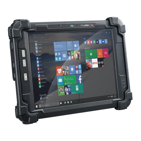
Page 19: Identifying The Device
Introduction Identifying the Device Overview Figure 1. Overview Table 2. Overview Item Description Left view See “Side View” on page 14 for further information. Front view See “Front View” on page 12 for further information. Rear view See “Rear View” on page 15 for further information. Easy to grip rubber bumpers enable the rugged tablet to withstand Rubber bumpers shocks and drop for use in demanding environments. - Page 20 Introduction Front View Figure 2. Front View Table 3. Front View Item Description Front camera 2.0 Mega-Pixels camera. Touch screen 10 finger capacitive touch. NFC sensing area For detecting NFC devices. The Power LED lights when the device is on or when the battery is Power LED being charged.
- Page 21 Introduction LED Status Table 4. LED Status Item Status Description Green: On Power on / not charging Green: Sleep mode / not charging Blinking Power Green: Off Power off Amber: On Power on / charging Amber: Sleep mode or power off but charging Blinking White: On Accessing SSD...
- Page 22 Introduction Side View Figure 4. Side Views Left view Right view Table 6. Side View Item Description DC-IN cover Open to access the DC-IN jack. Power key Turns the PM-522 on or off. Lock key Lock all the keys except for the Power and Lock keys. RF setting key Show Windows 8 Charm Bar.
- Page 23 Introduction Rear View Figure 5. Rear View Table 7. Rear View Item Description Rear camera 5.0 Mega-Pixels camera with LED auxiliary light. Open to access SIM port and access connectors for optional snap-on Add-on cover modules. External battery Open to access external battery connector. The external battery is connector cover optional.
-
Page 24: Dimensions
Introduction Dimensions The following image lists the device dimensions without add-ons (mm/inches). Figure 6. Front View Dimensions 293.87 / 11.57 292.00 / 11.50 Figure 7. Side View Dimensions 41.00 / 1.61... -
Page 25: Touch Screen
Introduction Touch Screen Always use the point of the stylus for clicking or making strokes on the touch screen. Never use an actual pen, pencil, or sharp/abrasive object on the touch screen. The stylus is used as if it were a pen or pencil. Touch the screen with the tip of the stylus then remove the stylus from the screen. -
Page 26: Chapter 2. Getting Started
This section provides an outline of the steps necessary to setup a new PM-522. A detailed guide follows the listed items, see as follows. For additional technical assistance, contact your RuggON representative. See “Contacting RuggON” on page 72. It is recommended to installing or remove accessories on a clean, well-lit work surface. -
Page 27: Installing The Bumpers
Getting Started Installing the Bumpers The bumpers provide the PM-522 protection from minor damage with easy access to all keys and ports. Warranty is void if rubber bumpers are not properly installed. Align the screw holes on the left bumper with the screw holes on the PM-522. The left bumper fits over three keys (left side panel) and the DC-IN compartment. - Page 28 Getting Started Install the right bumper to the PM-522. (Flip up a little protective film if necessary) Figure 9. Installing the Right Bumper Once the rubber bumpers are installed, it is recommended to not remove them. Secure the bumpers and the PM-522 with screws. Figure 10.
-
Page 29: Removing The Add-On Compartment Cover
Getting Started Removing the Add-on Compartment Cover The add-on compartment is located on the rear side of the device. For further information see “Overview” on page 11 Place the device display side down on a clean work surface. Locate the add-on compartment cover. Figure 11. -
Page 30: Replacing The Add-On Compartment Cover
Getting Started Replacing the Add-on Compartment Cover The add-on compartment is located on the rear side of the device. For further information see “Overview” on page 11 Place the device display side down on a clean work surface. Locate the add-on compartment cover. Figure 14. -
Page 31: Installing The Micro Sim Card
Getting Started Installing the Micro SIM Card The device includes a micro SIM card slot for cellular and wireless connection. Only a micro SIM card is supported in the slot. Check with your network or cellular service provider for availability and cost rates. Power down the device. -
Page 32: Removing The Micro Sim Card
Getting Started Removing the Micro SIM Card Power down the device. Remove the add-on compartment cover. See “Removing the Add-on Compartment Cover” on page 21. Press the micro SIM card in and release it. The card springs out. Grasp the micro SIM card and remove it from the slot. Figure 17. -
Page 33: Replacing The I/O Cover
Getting Started Flip the I/O cover and pull out the I/O cover. Figure 19. Removing the I/O Cover Replacing the I/O Cover Place the device display side down on a clean work surface. Locate the I/O cover. Figure 20. Rear View: Locating the I/O Cover I/O Cover Align the plastic tab on the I/O cover with the PM-522. -
Page 34: Connecting To External Cabling
Getting Started Flip the I/O cover and install. Figure 22. Installing the I/O cover The I/O cover must be inserted correctly to prevent internal damage to the device. Connecting to External Cabling To prevent damage to the device, connect all cabling and accessories before powering up the device. - Page 35 Getting Started Connect Ethernet Cabling The PM-522 provide mini USB to RJ45 dongle for connecting Ethernet. Use a shielded cable is required to maintain emissions and susceptibility compliance. Open the I/O cover. See “Removing the I/O Cover” on page 24. Connect the mini USB to RJ45 dongle to mini USB port on the PM-522.
-
Page 36: Handstrap And Shoulder Strap
Getting Started Handstrap and Shoulder Strap The PM-522 is equipped with a handstrap and a shoulder strap to provide users safety use. For more information, see “Connecting the Handstrap” on page 28 and “Connecting the Shoulder Strap” on page 31. Connecting the Handstrap Remove the screws securing the bumpers. - Page 37 Getting Started Connect to lock the handstrap on the D-rings. When handstrap is installed, the stylus can place with handstrap. Figure 28. Connecting the Handstrap Removing the Handstrap Unlock the handstrap from the D-rings. Figure 29. Removing the Handstrap...
- Page 38 Getting Started Remove the D-rings. Figure 30. Removing the D-rings Secure the bumper and the PM-522 with screws. Figure 31. Securing the Screws...
- Page 39 Getting Started Connecting the Shoulder Strap Remove the screws securing the bumpers. Figure 32. Removing the Screws Install the D-rings. Make sure the D-rings are tightly secured before attaching the shoulder strap. Figure 33. Installing the D-rings...
- Page 40 Getting Started Attach the clips to the D-rings to attach the shoulder strap. Figure 34. Connecting the Shoulder Strap Removing the Shoulder Strap Press in the clips to release them from the D-rings. Remove the clips. Figure 35. Removing the Shoulder Strap...
- Page 41 Getting Started Remove the D-rings. Figure 36. Removing the D-rings Secure the bumper and the PM-522 with screws. Figure 37. Securing the Screws...
-
Page 42: Charging The Battery
Getting Started Charging the Battery When you use the AC adapter to connect your PM-522 to a power outlet, the internal and external (optional) battery will automatically begin to recharge. While the battery is charging, the Power LED will be active. When the battery is fully charged, the Power LED is lit a solid green. -
Page 43: Installing The External Battery
Getting Started Insert one end of the cover first and angle the cover to seat it in place. Push in the cover to seal the DC-IN compartment. Figure 41. Installing the DC-IN Cover The DC-IN cover must be inserted correctly to prevent internal damage to the device. Installing the External Battery The external battery is an optional component. - Page 44 Getting Started Flip the connector cover up to remove it from the compartment. Figure 43. Removing the Connector Cover Install the connector cover in the placeholder. Figure 44. Placing the Connector Cover in the Placeholder Align the tabs on the external battery bracket with the slots on the rear side of the PM-522 . Figure 45.
- Page 45 Getting Started Push the external battery bracket forward to lock. Figure 46. Installing the External Battery Bracket Securing the external battery bracket and the PM-522 with screws. Figure 47. Securing the Screws Align the tabs on the external battery with the slots on the external battery bracket. Angle the battery in place and set the tabs in the bracket slots.
-
Page 46: Removing The External Battery
Getting Started 11. Press the locking switch on the top-left side to lock the external battery. Figure 49. Locking the External Battery Removing the External Battery Press the locking switch on the top-left side to the unlock position. Figure 50. Unlock the External Battery... - Page 47 Getting Started Press and hold the release button as shown in the image to release the battery. Hold the battery and angle the top side up to remove. . Figure 51. Removing the External Battery Remove the screws securing the external battery bracket. Figure 52.
- Page 48 Getting Started Push the external battery bracket toward the bottom of the PM-522 to release the bracket. Figure 53. Releasing the External Battery Bracket Remove the external battery bracket. Figure 54. Removing the External Battery Bracket Remove the connector cover from the placeholder. Figure 55.
-
Page 49: Installing The Barcode Scanner (Optional)
Getting Started Install the connector cover in the external battery compartment to protect the battery connector. Figure 56. Installing the Connector Cover Installing the Barcode Scanner (Optional) Before installing an add-on module, disconnect the AC adapter and set the DIP switch to OFF. Remove the add-on compartment cover. - Page 50 Getting Started Press the barcode scanner board to install until a “click” sound. Figure 58. Installing the Barcode Scanner Board Secure the barcode scanner board and the PM-522 with screws. Figure 59. Securing the Barcode Scanner Board Connect the FFC and lock the connector. Figure 60.
- Page 51 Getting Started Align the pins on the barcode scanner with the pins on the top side of the PM-522. Figure 61. Align the Barcode Scanner with the PM-522 Slide down the barcode scanner until it’s in place. Before you slide down the barcode scanner, please make sure the FFC will not be covered by the module.
-
Page 52: Removing The Barcode Scanner (Optional)
Getting Started Removing the Barcode Scanner (Optional) Before installing an add-on module, disconnect the AC adapter and set the DIP switch to OFF. Remove the screws securing the barcode scanner. Figure 64. Removing the Screws Slide up the barcode scanner to remove. Figure 65. -
Page 53: Installing The Mag Strip Reader (Optional)
Getting Started Remove the screws securing the barcode scanner board. Figure 67. Removing the Screws Flip up the barcode scanner board to remove. Figure 68. Removing the Barcode Scanner Board Replace the add-on compartment cover. See “Replacing the Add-on Compartment Cover” on page 22. - Page 54 Getting Started Press the mag strip reader board to install until a “click” sound. Figure 70. Installing the Mag Strip Reader Board Secure the mag strip reader board and the PM-522 with screws. Figure 71. Securing the Mag Strip Reader Board Connect the cables.
- Page 55 Getting Started Align the pins on the mag strip reader with the pins on the top side of the PM-522. Figure 73. Align the Mag Strip Reader with the PM-522 Slide down the mag strip reader until it’s in place. Before you slide down the mag strip reader, please make sure the cable will not be covered by the module.
-
Page 56: Removing The Mag Strip Reader (Optional)
Getting Started Removing the Mag Strip Reader (Optional) Before installing an add-on module, disconnect the AC adapter and set the DIP switch to OFF. Remove the screws securing the mag strip reader. Figure 76. Removing the Screws Slide up the mag strip reader to remove. Figure 77. - Page 57 Getting Started Remove the screws securing the mag strip reader board. Figure 79. Removing the Screws Flip up the mag strip reader board to remove. Figure 80. Removing the Mag Strip Reader Board Replace the add-on compartment cover. See “Replacing the Add-on Compartment Cover” on page 22.
-
Page 58: Installing The Smart Card Reader (Optional)
Getting Started Installing the Smart Card Reader (Optional) Before installing an add-on module, disconnect the AC adapter and set the DIP switch to OFF. Remove the add-on compartment cover. See “Removing the Add-on Compartment Cover” on page 21. Align the connector on the smart card reader board with the connector on the PM-522. Figure 81. - Page 59 Getting Started Connect the FFC and lock the connector. Figure 84. Connecting the FFC Align the smart card reader with the top side of the PM-522. Figure 85. Align the Smart Card Reader with the PM-522 Flip down the smart card reader until it’s in place. Figure 86.
-
Page 60: Removing The Smart Card Reader (Optional)
Getting Started Secure the smart card reader and the PM-522 with provided screws. Figure 87. Installing the Screws Removing the Smart Card Reader (Optional) Before installing an add-on module, disconnect the AC adapter and set the DIP switch to OFF. Remove the screws securing the smart card reader. - Page 61 Getting Started Unlock the connector and disconnect the FFC. Figure 90. Disconnecting the FFC Remove the screws securing the smart card reader board. Figure 91. Removing the Screws Flip up the smart card reader board to remove. Figure 92. Removing the Smart Card Reader Board Replace the add-on compartment cover.
-
Page 62: Removing The Protective Film From The Display
Getting Started Removing the Protective Film from the Display The front display of the PM-522 is protected during transport by a transparent film. This film should remain on the front display during assembly to avoid damage to the front display surface. Only remove the film once all of the assembly work has been completed. -
Page 63: Chapter 3. Operation
Operation Chapter 3. Operation First Time Use Flip up the external battery connector cover and lift it up. Figure 94. Removing the External Battery Cover Switch the DIP switch to the ON position. Figure 95. Switching the DIP Switch Install the external battery cover over the battery connector. Figure 96. -
Page 64: Powering The Device On And Off
Operation Powering the Device On and Off Powering On the Device Only power on the PM-522 after connecting all of the peripherals and cabling. Locate the power button. Press and hold the power button until the screen lights. The device runs through the start up sequence and powers up. - Page 65 Operation The Wi-Fi menu displays. By the default, the Wi-Fi menu is set to Off. Tap the bar next to Off to toggle Wi-Fi to On. This enables the Wi-Fi option. Once W-Fi is enabled a listing of all available wireless networks displays. The wireless networks with the strongest signal are atop the list.
-
Page 66: Chapter 4. Using Bios Setup Utility
Using BIOS Setup Utility Chapter 4. Using BIOS Setup Utility Your ruggedized tablet has a BIOS setup utility which allows you to configure important system settings, including settings for the Boot and AP menus as well as the device’s basic settings--the system reads the basic settings during initialization in order to boot correctly When to Use the BIOS Setup Utility You need to run the BIOS Setup utility when:... - Page 67 Using BIOS Setup Utility Due to the device’s fast boot up and boot down time, there is only a small time frame of a few seconds between the release of the Power button and the opportunity to press the Windows Home key.
-
Page 68: Installation An Operating System
Using BIOS Setup Utility Installation an Operating System Setting Up a Windows 7 Installation Environment There are several settings in BIOS that must be modified before you can install a Windows 7 operating system. Use the following guidelines to prepare the BIOS environment: „... - Page 69 Using BIOS Setup Utility Step 2 Enable Legacy Boot „ Access the BIOS Setup Utility, see “Accessing the BIOS Setup Utility” on page 58. Navigate to APP Menu > Main > Boot Features. Locate the Legacy Boot setting and tap on the menu to select On enable legacy boot. Figure 102.
- Page 70 Using BIOS Setup Utility Step 4: Save the Settings „ After you configure BIOS, you will need to save the settings. Navigate to APP Menu > Exit and tap Exit Saving Changes. Figure 104. Exit the BIOS Utility A prompt display, tap Yes to save the configuration. The BIOS settings are configured and the Windows 7 operating system can be installed.
-
Page 71: Bios Passwords
Using BIOS Setup Utility BIOS Passwords Setting Up a Supervisor Password To setup a supervisor password, follow the procedure as described: Go to APP Menu > Security > Account’s Password Status. Tap the Enter icon next to Setup the Supervisor Password to access the virtual keyboard. Figure 105. - Page 72 Using BIOS Setup Utility Verification of the password is required. Tap the same password again and tap Enter to confirm the new password. Navigate to APP Menu > Exit. Figure 107. Exit Screen Tap Exit Saving Changes to display the confirmation screen. Tap Yes to save the new configuration settings.
-
Page 73: Ec And Bios
Using BIOS Setup Utility EC and BIOS Updating BIOS This procedure allows you to update and reflash the system BIOS. Both procedures follow the same steps as described in the following. Make sure to protect your device from power loss during the BIOS update procedure to prevent irreparable damage to your system’s mainboard. - Page 74 Using BIOS Setup Utility Tap Change PC settings. Figure 109. Change PC Settings From the PC settings menu, tap Update and recovery to continue. Figure 110. Update and Recovery...
- Page 75 Using BIOS Setup Utility From the Update and recovery screen, tap Recovery. The Advanced startup option displays. Figure 111. Recovery Under Advanced startup, tap Restart now. Figure 112. Restart Now...
- Page 76 Using BIOS Setup Utility 10. Tap Use a device to select a boot up preference. Figure 113. Use a Device 11. From the Use a device menu, tap Internal Shell to open the command screen. Make sure connect the PM-522 to the AC adapter to prevent a sudden loss of power. Figure 114.
- Page 77 Using BIOS Setup Utility 12. In the command screen, enter fs1: to select the USB device already connected to the device. The command directs you to the USB device’s root menu. Figure 115. Internal Shell Command Screen 13. If the BIOS file is in a folder and not in the root directory, navigate to the target folder. 14.
-
Page 78: Chapter 5. Troubleshooting
If you send the computer in for service, it is your responsibility to save the computer data and configuration. RuggON is responsible only for ensuring that the hardware matches the original configuration when repairing or replacing the computer. -
Page 79: Troubleshoot Operating The Computer
The computer appears to be locked up and you cannot enter data. Restart the computer. Call Product Support Simple instructions please contact the dealer, contact ruggon representative, or leave a message visit the RuggON website at www.ruggon.com. To better assist you have the following information ready: Configuration number „... - Page 80 Prevent using any kind of chemical solvent, acidic or alkali solution. „ Returning the Device Please put the contents in the original package gently when you need to return the PM-522. Contacting RuggON If you experience technical difficulties, please consult your distributor or contact the technical services department: www.ruggon.com...
Need help?
Do you have a question about the PM-522B4N and is the answer not in the manual?
Questions and answers