Table of Contents
Advertisement
Quick Links
ECN-360A-D2550 Em b e d d e d S ys te m
,
IEI Te c h n o lo g y Co rp .
MODEL:
ECN-360A-D2550
Em b e d d e d S ys te m with In te l® d u a l c o re Ato m ™ D2550 P ro c e s s o r,
Re v. 1.00 – 1 J u ly 2013
Two VGA, S ix US B 2.0, Fo u r COM,
Gb E a n d Ro HS Co m p lia n t
Us e r Ma n u a l
P a g e i
Advertisement
Table of Contents

Subscribe to Our Youtube Channel
Related Manuals for IEI Technology ECN-360A-D2550


Summary of Contents for IEI Technology ECN-360A-D2550
- Page 1 ECN-360A-D2550 Em b e d d e d S ys te m IEI Te c h n o lo g y Co rp . MODEL: ECN-360A-D2550 Em b e d d e d S ys te m with In te l® d u a l c o re Ato m ™ D2550 P ro c e s s o r, Two VGA, S ix US B 2.0, Fo u r COM,...
- Page 2 ECN-360A-D2550 Em b e d d e d S ys te m Re vis io n Date Version Changes 1 July 2013 1.00 Initial release P a g e ii...
- Page 3 ECN-360A-D2550 Em b e d d e d S ys te m Co p yrig h t COP YRIGHT NOTICE The information in this document is subject to change without prior notice in order to improve reliability, design and function and does not represent a commitment on the part of the manufacturer.
-
Page 4: Table Of Contents
ECN-360A-D2550 Em b e d d e d S ys te m Ta b le o f Co n te n ts 1 INTRODUCTION ......................1 1.1 O ........................2 VERVIEW 1.2 M ....................2 ODEL ARIATIONS 1.3 F ........................2 EATURES 1.4 T... - Page 5 ECN-360A-D2550 Em b e d d e d S ys te m 4.1.3 External Interface Panel Connectors ............... 25 4.2 I ..............26 NTERNAL ERIPHERAL ONNECTORS 4.2.1 5 V SATA Power Connectors ................26 4.2.2 Audio Connector ....................26 4.2.3 Backlight Inverter Connector ................27 4.2.4 Battery Connector ....................
- Page 6 ECN-360A-D2550 Em b e d d e d S ys te m 5.2 M ........................50 5.3 A ....................... 51 DVANCED 5.3.1 ACPI Settings ....................51 5.3.2 RTC Wake Settings ................... 52 5.3.3 CPU Configuration ..................54 5.3.4 IDE Configuration ................... 55 5.3.5 USB Configuration ...................
- Page 7 ECN-360A-D2550 Em b e d d e d S ys te m C.2 S ................87 ETUP ROCEDURE FOR INDOWS C.2.1 Hardware and BIOS Setup ................88 C.2.2 Create Partitions ..................... 88 C.2.3 Install Operating System, Drivers and Applications ........92 C.2.4 Building the Recovery Partition ..............
- Page 8 ECN-360A-D2550 Em b e d d e d S ys te m Lis t o f Fig u re s Figure 1-1: ECN-360A-D2550 ......................2 Figure 1-2: ECN-360A-D2550 Front Panel ..................5 Figure 1-3: ECN-360A-D2550 Rear Panel ..................6 Figure 1-4: Physical Dimensions (mm) ..................7 Figure 3-1: Retention Screws Removal ..................14...
- Page 9 ECN-360A-D2550 Em b e d d e d S ys te m Figure 4-17: USB Connector Location ..................39 Figure 4-18: External Peripheral Interface Connector ..............40 Figure 4-19: RJ-45 Ethernet Connector ..................41 Figure 4-20: VGA Connector .......................42 Figure 4-21: AT/ATX Power Selection Jumper Location ............44 Figure 4-22: Clear CMOS Jumper Location ................45...
- Page 10 ECN-360A-D2550 Em b e d d e d S ys te m Figure C-28: Press any key to continue ...................103 Figure C-29: Partitions for Linux ....................105 Figure C-30: Manual Recovery Environment for Linux ............106 Figure C-31: Access menu.lst in Linux (Text Mode) ...............107 Figure C-32: Recovery Tool Menu ....................107...
- Page 11 ECN-360A-D2550 Em b e d d e d S ys te m Lis t o f Ta b le s Table 1-1: Model Variations ......................2 Table 1-2: Technical Specifications ....................4 Table 2-1: Package List Contents ....................11 Table 4-1: Peripheral Interface Connectors ................25 Table 4-2: Rear Panel Connectors ....................25...
-
Page 12: Introduction
ECN-360A-D2550 Em b e d d e d S ys te m Ch a p te r In tro d u c tio n P a g e 1... -
Page 13: Overview
204-pin DDR3 SDRAM SO-DIMM module up to 4 GB (2GB memory preinstalled). The ECN-360A-D2550 supports a 2.5” SATA HDD with up to 3 Gb/s data transfer rate. Four serial ports and six USB 2.0 ports ensure simplified connectivity to a variety of external peripheral devices. -
Page 14: Technical Specifications
ECN-360A-D2550 Em b e d d e d S ys te m 1.4 Te c h n ic a l Sp e c ific a tio n s The ECN-360A-D2550 technical specifications are listed in Table 1-1. Ch a s s is... -
Page 15: Front Panel
ECN-360A-D2550 Em b e d d e d S ys te m 1 x Full size (support mSATA) P CIe Min i 1 x Half size P o we r 9~28V DC P o we r In p u t... -
Page 16: Rear Panel
ECN-360A-D2550 Em b e d d e d S ys te m Figure 1-2: ECN-360A-D2550 Front Panel 1.6 Re a r P a n e l The rear panel of the ECN-360A-D2550 has the following features (Figure 1-3): 1 x Line-out ... -
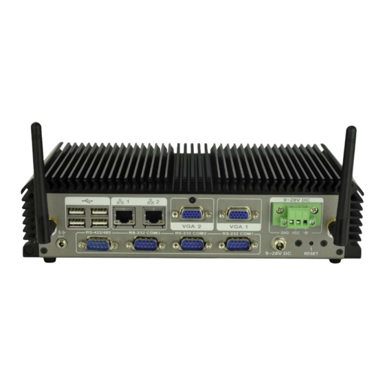
Page 17: Figure 1-3: Ecn-360A-D2550 Rear Panel
ECN-360A-D2550 Em b e d d e d S ys te m Figure 1-3: ECN-360A-D2550 Rear Panel P a g e 6... -
Page 18: Dimensions
ECN-360A-D2550 Em b e d d e d S ys te m 1.7 Dim e n s io n s The physical dimensions are shown below: Figure 1-4: Physical Dimensions (mm) P a g e 7... -
Page 19: Unpacking
ECN-360A-D2550 Em b e d d e d S ys te m Ch a p te r Un p a c kin g P a g e 8... -
Page 20: Anti - Static Precautions
ECN-360A-D2550 Em b e d d e d S ys te m 2.1 An ti-s ta tic P re c a u tio n s WARNING: Failure to take ESD precautions during installation may result in permanent damage to the ECN-360A-D2550 and severe injury to the user. -
Page 21: Unpacking Checklist
ECN-360A-D2550 Em b e d d e d S ys te m 2.3 Un pa c kin g Ch e c klis t NOTE: If some of the components listed in the checklist below are missing, please do not proceed with the installation. Contact the IEI reseller or vendor you purchased the ECN-360A-D2550 from or contact an IEI sales representative directly. -
Page 22: Table 2-1: Package List Contents
ECN-360A-D2550 Em b e d d e d S ys te m Qu a n tity Ite m a n d P a rt Nu m b e r Im a g e Utility CD One Key Recovery CD Table 2-1: Package List Contents... -
Page 23: Installation
ECN-360A-D2550 Em b e d d e d S ys te m Ch a p te r In s ta lla tio n P a g e 12... -
Page 24: Installation Precautions
Electric shock and personal injury might occur if the rear panel of the ECN-360A-D2550 is opened while the power cord is still connected to an electrical outlet. -
Page 25: Figure 3-1: Retention Screws Removal
ECN-360A-D2550 Em b e d d e d S ys te m Remove six retention screws from the bottom panel (Figure 3-1). S te p 1: Figure 3-1: Retention Screws Removal Open the bottom panel and locate the HDD bracket (Figure 3-2). -
Page 26: W I -F I Antenna Installation (Wireless Model Only )
3.4 Wi-Fi An te n n a In s ta lla tio n (Wire le s s Mo d e l On ly) To install the Wi-Fi antennas to the ECN-360A-D2550 series for efficient wireless network transmission, follow the steps below. -
Page 27: Mount The System
ECN-360A-D2550 Em b e d d e d S ys te m Figure 3-4: Wi-Fi Antenna Installation 3.5 Mo u n t th e S ys te m To mount the embedded system onto a wall or some other surface using the two mounting brackets, please follow the steps below. -
Page 28: External Peripheral Interface Connectors
3.6.1 Au d io Co n n e c tio n The audio jack on the external audio connector enables the ECN-360A-D2550 to be connected to a stereo sound setup. To install the audio devices, follow the steps below. -
Page 29: Lan Connection
If the plug on your speakers is different, an adapter will need to be used to plug them into the audio jack. The audio jack on the ECN-360A-D2550 is a line-out port which connects to a headphone or a speaker. -
Page 30: Serial Port Connection
3.6.3 DB-9 S e ria l P o rt Co n n e c tio n There are three RS-232 DB-9 connectors and one RS-422/485 DB-9 connector of the ECN-360A-D2550 for serial device connection. Follow the steps below to connect a serial device to the DB-9 connector of the ECN-360A-D2550. -
Page 31: Usb Device Connection
There are six USB 2.0 connectors on the ECN-360A-D2550. To connect a USB device, please follow the instructions below. Locate the USB connectors. The locations of the USB connectors are shown S te p 1: in Chapter 1. -
Page 32: Vga Monitor Connection
ECN-360A-D2550 Em b e d d e d S ys te m Figure 3-9: USB Device Connection Insert the device connector. Once aligned, gently insert the USB device S te p 3: connector into the onboard connector. 3.6.5 VGA Mo n ito r Co n n e c tio n The ECN-360A-D2550 has two female DB-15 connectors on the external peripheral interface panel. -
Page 33: Figure 3-11: Vga Connector
ECN-360A-D2550 Em b e d d e d S ys te m Figure 3-10: VGA Connector Secure the connector. Secure the DB-15 VGA connector from the VGA S te p 4: monitor to the external interface by tightening the two retention screws on either side of the connector. -
Page 34: System Motherboard
ECN-360A-D2550 Em b e d d e d S ys te m Ch a p te r S ys te m Mo th e rb o a rd P a g e 23... -
Page 35: Peripheral Interface Connectors
ECN-360A-D2550 Em b e d d e d S ys te m 4.1 P e rip h e ra l In te rfa c e Co n n e c to rs This chapter details all the jumpers and connectors. -
Page 36: External Interface Panel Connectors
ECN-360A-D2550 Em b e d d e d S ys te m Co n n e c to r Typ e La b e l Backlight inverter connector 5-pin wafer INV1 Battery connector 2-pin wafer Digital Input/Output (DIO) connector 10-pin header... -
Page 37: Sata Power Connectors
ECN-360A-D2550 Em b e d d e d S ys te m 4.2 In te rn a l P e rip h e ra l Co n n e c to rs The section describes all of the connectors on the motherboard. -
Page 38: Backlight Inverter Connector
ECN-360A-D2550 Em b e d d e d S ys te m The 10-pin audio connector is connected to external audio devices including speakers and microphones for the input and output of audio signals to and from the system. Figure 4-3: Audio Connector Location... -
Page 39: Battery Connector
ECN-360A-D2550 Em b e d d e d S ys te m Figure 4-4: Backlight Inverter Connector Location Description LCD_BKLTCTL GROUND +12V GROUND BACKLIGHT ENABLE Table 4-5: Backlight Inverter Connector Pinouts 4.2.4 Ba tte ry Co n n e c to r... -
Page 40: Digital Input/Output (Dio) Connector
ECN-360A-D2550 Em b e d d e d S ys te m Figure 4-5: Battery Connector Location Description Battery+ Table 4-6: Battery Connector Pinouts 4.2.5 Dig ita l In p u t/Ou tp u t (DIO) Co n n e c to r... -
Page 41: Fan Connectors
ECN-360A-D2550 Em b e d d e d S ys te m Description Description Output 3 Output 2 Output 1 Output 0 Input 3 Input 2 Input 1 Input 0 Table 4-7: Digital I/O Connector Pinouts 4.2.6 Fa n Co n n e c to rs... -
Page 42: Front Panel Connector
ECN-360A-D2550 Em b e d d e d S ys te m 4.2.7 Fro n t P a n e l Co n n e c to r CN La b e l: F_P ANEL1 10-pin header CN Typ e :... -
Page 43: Lvds1 Connector
ECN-360A-D2550 Em b e d d e d S ys te m The keyboard and mouse connector can be connected to a standard PS/2 cable or PS/2 Y-cable to add keyboard and mouse functionality to the system. Figure 4-9: Keyboard/Mouse Connector Location... -
Page 44: Pcie Mini Card Slots
ECN-360A-D2550 Em b e d d e d S ys te m Figure 4-10: LVDS1 Connector Location Description Description LVDS_DATA0 LVDS_DATA0# LVDS_DATA1 LVDS_DATA1# LVDS_DATA2 LVDS_DATA2# LVDS_CLK LVDS_CLK# LDDC_DATA LDDC_CLK VCC_LCD VCC_LCD VCC_LCD VCC_LCD Table 4-11: LVDS1 Connector Pinouts 4.2.10 P CIe Min i Ca rd S lo ts... -
Page 45: Figure 4-11: Pcie Mini Card Slot Locations
ECN-360A-D2550 Em b e d d e d S ys te m NOTE: The M_PCIE1 slot supports mSATA devices. However, the SATA1 connector will be disabled when an mSATA device is installed to the M_PCIE1 slot. Figure 4-11: PCIe Mini Card Slot Locations... -
Page 46: Power Connector (9V~28V)
ECN-360A-D2550 Em b e d d e d S ys te m Description Description SMBCLK PCIE_TXN SMBDATA PCIE_TXP USBD- USBD+ VCC3 VCC3 1.5V M-SATA Detect VCC3 Table 4-12: PCIe Mini Card Slot Pinouts 4.2.11 P owe r Co n n e c to r (9V~28V) -
Page 47: Serial Port Connectors
ECN-360A-D2550 Em b e d d e d S ys te m Description Description Table 4-13: Power Connector Pinouts 4.2.12 RS -232 S e ria l P o rt Co n n e c to rs CN La b e l:... -
Page 48: Rs-422/485 Serial Port Connector
ECN-360A-D2550 Em b e d d e d S ys te m 4.2.13 RS -422/485 S e ria l P ort Co n n e c to r CN La b e l: COM4 4-pin wafer CN Typ e :... -
Page 49: So-Dimm Connector
ECN-360A-D2550 Em b e d d e d S ys te m NOTE: The SATA1 connector will be disabled when an mSATA device is installed to the M_PCIE1 slot. Figure 4-15: SATA Drive Connector Locations Description Table 4-16: SATA Drive Connector Pinouts 4.2.15 S O-DIMM Co n n e c to r... -
Page 50: Usb Connector
ECN-360A-D2550 Em b e d d e d S ys te m Figure 4-16: SO-DIMM Connector Location 4.2.16 US B Co n n e c to r CN La b e l: US B4 8-pin header CN Typ e :... -
Page 51: External Peripheral Interface Connector Panel
ECN-360A-D2550 Em b e d d e d S ys te m 4.3 Exte rn a l P e rip h e ra l In te rfa c e Co n n e c to r P a n e l The figure below shows the external periphe4ral interface connector (EPIC) panel. -
Page 52: Usb Connectors
ECN-360A-D2550 Em b e d d e d S ys te m Figure 4-19: RJ-45 Ethernet Connector Description Description on: linked off: 10 Mb/s blinking: data is being sent/received green: 100 Mb/s orange: 1000 Mb/s Table 4-19: RJ-45 Ethernet Connector LEDs 4.3.2 US B Co n n e c to rs... -
Page 53: Vga Connectors
ECN-360A-D2550 Em b e d d e d S ys te m 4.3.3 VGA Co n n e c to rs CN La b e l: VGA1, VGA2 15-pin Female CN Typ e : CN Lo c a tio n :... -
Page 54: Jumper Settings
ECN-360A-D2550 Em b e d d e d S ys te m 4.4 J u m p e r S e ttin g s NOTE: A jumper is a metal bridge used to close an electrical circuit. It consists of two or... -
Page 55: Clear Cmos Jumper
ECN-360A-D2550 Em b e d d e d S ys te m Setting Description Use AT power Table 4-23: AT/ATX Power Selection Jumper Settings Figure 4-21: AT/ATX Power Selection Jumper Location 4.4.2 Cle a r CMOS J u m p e r... -
Page 56: Lvds1 Voltage Selection
ECN-360A-D2550 Em b e d d e d S ys te m Figure 4-22: Clear CMOS Jumper Location 4.4.3 LVDS 1 Vo lta g e S e le c tio n WARNING: Permanent damage to the screen and ECN-360A-D2550 may occur if the wrong voltage is selected with this jumper. -
Page 57: Msata/Pcie Mini Selection
ECN-360A-D2550 Em b e d d e d S ys te m Figure 4-23: LVDS1 Voltage Selection Jumper Location 4.4.4 m S ATA/P CIe Min i S e le c tio n J u m p e r La b e l:... -
Page 58: Bios
ECN-360A-D2550 Em b e d d e d S ys te m Ch a p te r BIOS P a g e 47... -
Page 59: Introduction
ECN-360A-D2550 Em b e d d e d S ys te m 5.1 In tro d u c tio n The BIOS is programmed onto the BIOS chip. The BIOS setup program allows changes to certain system settings. This chapter outlines the options that can be changed. -
Page 60: Getting Help
ECN-360A-D2550 Em b e d d e d S ys te m Ke y Fu n c tio n Esc key Main Menu – Quit and not save changes into CMOS Status Page Setup Menu and Option Page Setup Menu --... -
Page 61: Main
ECN-360A-D2550 Em b e d d e d S ys te m 5.2 Ma in The Main BIOS menu (BIOS Menu 1) appears when the BIOS Setup program is entered. The Main menu gives an overview of the basic system information. -
Page 62: Advanced
ECN-360A-D2550 Em b e d d e d S ys te m S ys te m Tim e [xx:xx:xx] Use the System Time option to set the system time. Manually enter the hours, minutes and seconds. 5.3 Ad va n c e d... -
Page 63: Rtc Wake Settings
ECN-360A-D2550 Em b e d d e d S ys te m Aptio Setup Utility – Copyright (C) 2011 American Megatrends, Inc. Advanced ACPI Settings Select the highest ACPI sleep state the system will enter when the ACPI Sleep State... - Page 64 ECN-360A-D2550 Em b e d d e d S ys te m Aptio Setup Utility – Copyright (C) 2011 American Megatrends, Inc. Advanced Wake system with Fixed Time [Disabled] Enable or disable System wake on alarm event. When enabled, System will...
-
Page 65: Cpu Configuration
ECN-360A-D2550 Em b e d d e d S ys te m 5.3.3 CP U Co n fig u ra tio n Use the CPU Configuration menu (BIOS Menu 5) to view detailed CPU specifications and configure the CPU. Aptio Setup Utility – Copyright (C) 2011 American Megatrends, Inc. -
Page 66: Ide Configuration
ECN-360A-D2550 Em b e d d e d S ys te m Hyp e r-Th re a d in g [En a b le d ] Use the Hyper-Threading BIOS option to enable or disable the Intel Hyper-Threading Technology. -
Page 67: Usb Configuration
ECN-360A-D2550 Em b e d d e d S ys te m 5.3.5 US B Co n fig u ra tio n Use the USB Configuration menu (BIOS Menu 7) to read USB configuration information and configure the USB settings. -
Page 68: F81866 Super Io Configuration
ECN-360A-D2550 Em b e d d e d S ys te m Legacy USB support enabled Enabled EFAULT Auto Legacy USB support disabled if no USB devices are connected 5.3.6 F81866 S u pe r IO Co nfig u ra tio n Use the F81866 Super IO Configuration menu (BIOS Menu 8) to set or change the configurations for the serial ports. -
Page 69: Serial Port N Configuration
ECN-360A-D2550 Em b e d d e d S ys te m 5.3.6.1 S e ria l P o rt n Co n fig u ra tio n Use the Serial Port n Configuration menu (BIOS Menu 9) to configure the serial port n. - Page 70 ECN-360A-D2550 Em b e d d e d S ys te m Serial Port I/O port address is 2F8h and the interrupt IO=2F8h; IRQ=3, 4 address is IRQ3, 4 IO=3E8h; Serial Port I/O port address is 3E8h and the interrupt...
- Page 71 ECN-360A-D2550 Em b e d d e d S ys te m 5.3.6.1.3 S e ria l P o rt 3 Co n fig u ra tio n S e ria l P o rt [En a b le d ] Use the Serial Port option to enable or disable the serial port.
- Page 72 ECN-360A-D2550 Em b e d d e d S ys te m 5.3.6.1.4 S e ria l P o rt 4 Co n fig u ra tio n S e ria l P o rt [En a b le d ] Use the Serial Port option to enable or disable the serial port.
-
Page 73: F81866 H/W Monitor
ECN-360A-D2550 Em b e d d e d S ys te m 5.3.7 F81866 H/W Mo n ito r The F81866 H/W Monitor menu (BIOS Menu 10) contains the fan configuration submenus and displays operating temperature, fan speeds and system voltages. -
Page 74: Smart Fan Mode Configuration
ECN-360A-D2550 Em b e d d e d S ys te m VSB3V VBAT 5.3.7.1 S m a rt Fa n Mo d e Co nfig u ra tio n Use the Smart Fan Mode Configuration submenu (BIOS Menu 11) to configure fan temperature and speed settings. -
Page 75: Serial Port Console Redirection
ECN-360A-D2550 Em b e d d e d S ys te m 5.3.8 S e ria l P o rt Co n s o le Re d ire c tio n The Serial Port Console Redirection menu (BIOS Menu 12) allows the console redirection options to be configured. - Page 76 ECN-360A-D2550 Em b e d d e d S ys te m Bits p e r s e c o n d [115200] Use the Bits per second option to specify the serial port transmission speed. The speed must match the other side. Long or noisy lines may require lower speeds.
-
Page 77: Iei Feature
ECN-360A-D2550 Em b e d d e d S ys te m Sto p Bits [1] Use the Stop Bits option to specify the number of stop bits used to indicate the end of a serial data packet. Communication with slow devices may require more than 1 stop bit. -
Page 78: Chipset
ECN-360A-D2550 Em b e d d e d S ys te m 5.4 Ch ips e t Use the Chipset menu (BIOS Menu 14) to access the Host Bridge and Southbridge configuration menus. WARNING! Setting the wrong values for the Chipset BIOS selections in the Chipset BIOS menu may cause the system to malfunction. -
Page 79: Intel Igd Configuration
ECN-360A-D2550 Em b e d d e d S ys te m Aptio Setup Utility – Copyright (C) 2011 American Megatrends, Inc. Chipset > Intel IGD Configuration Config Intel IGD Settings ******* Memory Information ******* Memory Frequency 1067 MHz(DDR3) Total Memory... - Page 80 ECN-360A-D2550 Em b e d d e d S ys te m IGFX - Bo o t Typ e [VBIOS De fa u lt] Use the IGFX - Boot Type option to select the display device used by the system when it boots.
-
Page 81: South Bridge Configuration
ECN-360A-D2550 Em b e d d e d S ys te m 5.4.2 S o u th Brid g e Co n fig u ra tio n Use the South Bridge Configuration menu (BIOS Menu 17) to configure the Southbridge chipset. -
Page 82: Boot
ECN-360A-D2550 Em b e d d e d S ys te m S e t Sp re a d Sp e c tru m Fu n c tio n [Dis a b le d ] The Set Spread Spectrum Function option can help to improve CPU EMI issues. - Page 83 ECN-360A-D2550 Em b e d d e d S ys te m Does not enable the keyboard Number Lock automatically. To use the 10-keys on the keyboard, press the Number Lock key located on the upper left-hand corner of the 10-key pad. The Number Lock LED on the keyboard lights up when the Number Lock is engaged.
-
Page 84: Security
ECN-360A-D2550 Em b e d d e d S ys te m 5.6 S e c u rity Use the Security menu (BIOS Menu 19) to set system and user passwords. Aptio Setup Utility – Copyright (C) 2011 American Megatrends, Inc. - Page 85 ECN-360A-D2550 Em b e d d e d S ys te m Aptio Setup Utility – Copyright (C) 2011 American Megatrends, Inc. Main Advanced Chipset Boot Security Save & Exit Save Changes and Reset Reset the system after Discard Changes and Reset saving the changes.
-
Page 86: A Safety Precautions
ECN-360A-D2550 Em b e d d e d S ys te m Appendix S a fe ty P re c a u tio n s P a g e 75... -
Page 87: Safety Precautions
ECN-360A-D2550 Em b e d d e d S ys te m WARNING: The precautions outlined in this chapter should be strictly followed. Failure to follow these precautions may result in permanent damage to the ECN-360A-D2550. A.1 S a fe ty P re c a u tio n s Please follow the safety precautions outlined in the sections that follow: A.1.1 Ge n e ra l S a fe ty P re c a u tio n s... -
Page 88: Anti-Static Precautions
Electrostatic discharge (ESD) can cause serious damage to electronic components, including the ECN-360A-D2550. Dry climates are especially susceptible to ESD. It is therefore critical that whenever the ECN-360A-D2550 is opened and any of the electrical components are handled, the following anti-static precautions are strictly adhered to. -
Page 89: Product Disposal
When maintaining or cleaning the ECN-360A-D2550, please follow the guidelines below. A.2.1 Ma in te n a n c e a n d Cle a n in g Prior to cleaning any part or component of the ECN-360A-D2550, please read the details below. -
Page 90: Cleaning Tools
Some components in the ECN-360A-D2550 may only be cleaned using a product specifically designed for the purpose. In such case, the product will be explicitly mentioned in the cleaning tips. Below is a list of items to use when cleaning the ECN-360A-D2550. ... -
Page 91: B Bios Menu Options
ECN-360A-D2550 Em b e d d e d S ys te m Appendix BIOS Me n u Op tio n s P a g e 80... - Page 92 ECN-360A-D2550 Em b e d d e d S ys te m System Overview .........................50 System Date [xx/xx/xx] ......................50 System Time [xx:xx:xx] .......................51 ACPI Sleep State [S1 (CPU Stop Clock)] ................52 Wake system with Fixed Time [Disabled] ................53 ...
- Page 93 ECN-360A-D2550 Em b e d d e d S ys te m Bootup NumLock State [On] ....................71 Quiet Boot [Enabled] ......................72 Launch PXE OpROM [Disabled] ..................72 Option ROM Messages [Force BIOS] .................72 UEFI Boot [Disabled] ......................72 ...
-
Page 94: C One Key Recovery
ECN-360A-D2550 Em b e d d e d S ys te m Ap p e n d ix On e Ke y Re c o ve ry P a g e 83... -
Page 95: One Key Recovery Introduction
ECN-360A-D2550 Em b e d d e d S ys te m C.1 On e Ke y Re c o ve ry In tro d u c tio n The IEI one key recovery is an easy-to-use front end for the Norton Ghost system backup and recovery tool. -
Page 96: System Requirement
ECN-360A-D2550 Em b e d d e d S ys te m After completing the five initial setup procedures as described above, users can access the recovery tool by pressing <F3> while booting up the system. The detailed information of each function is described in Section C.5. -
Page 97: Supported Operating System
ECN-360A-D2550 Em b e d d e d S ys te m partitions. Please take the following table as a reference when calculating the size of the partition. OS Image after Ghost Compression Ratio Windows® 7 7 GB 5 GB Windows®... -
Page 98: Setup Procedure For Windows
ECN-360A-D2550 Em b e d d e d S ys te m Ubuntu 8.10 (Intrepid) Ubuntu 7.10 (Gutsy) Ubuntu 6.10 (Edgy) Debian 5.0 (Lenny) Debian 4.0 (Etch) SuSe 11.2 SuSe 10.3 NOTE: Installing unsupported OS versions may cause the recovery tool to fail. -
Page 99: Hardware And Bios Setup
ECN-360A-D2550 Em b e d d e d S ys te m C.2.1 Ha rdwa re a n d BIOS S e tu p Make sure the system is powered off and unplugged. S te p 1: Install a hard drive or SSD in the system. An unformatted and unpartitioned disk S te p 2: is recommended. -
Page 100: Figure C-2: Launching The Recovery Tool
ECN-360A-D2550 Em b e d d e d S ys te m Figure C-2: Launching the Recovery Tool S te p 3: The recovery tool setup menu is shown as below. Figure C-3: Recovery Tool Setup Menu S te p 4: Press <6>... -
Page 101: Figure C-4: Command Prompt
ECN-360A-D2550 Em b e d d e d S ys te m Figure C-4: Command Prompt S te p 5: The command prompt window appears. Type the following commands (marked in red) to create two partitions. One is for the OS installation; the other is for saving recovery files and images which will be an invisible partition. -
Page 102: Figure C-5: Partition Creation Commands
ECN-360A-D2550 Em b e d d e d S ys te m Figure C-5: Partition Creation Commands P a g e 91... -
Page 103: Install Operating System, Drivers And Applications
ECN-360A-D2550 Em b e d d e d S ys te m NOTE: Use the following commands to check if the partitions were created successfully. S te p 6: Press any key to exit the recovery tool and automatically reboot the system. -
Page 104: Building The Recovery Partition
ECN-360A-D2550 Em b e d d e d S ys te m C.2.4 Bu ild in g th e Re c o ve ry P a rtitio n Put the recover CD in the optical drive. S te p 1: Start the system. -
Page 105: Figure C-8: Building The Recovery Partition
ECN-360A-D2550 Em b e d d e d S ys te m S te p 5: The Symantec Ghost window appears and starts configuring the system to build a recovery partition. In this process the partition created for recovery files in Section C.2.2 is hidden and the recovery tool is saved in this partition. -
Page 106: Create Factory Default Image
ECN-360A-D2550 Em b e d d e d S ys te m C.2.5 Cre a te Fa c to ry De fa u lt Im a g e NOTE: Before creating the factory default image, please configure the system to a factory default environment, including driver and application installations. -
Page 107: Figure C-12: About Symantec Ghost Window
ECN-360A-D2550 Em b e d d e d S ys te m Figure C-12: About Symantec Ghost Window Use mouse to navigate to the option shown below (Figure C-13). S te p 4: Figure C-13: Symantec Ghost Path S te p 5: Select the local source drive (Drive 1) as shown in Figure C-14. -
Page 108: Figure C-14: Select A Local Source Drive
ECN-360A-D2550 Em b e d d e d S ys te m Figure C-14: Select a Local Source Drive S te p 6: Select a source partition (Part 1) from basic drive as shown in Figure C-15. Then click OK. -
Page 109: Figure C-16: File Name To Copy Image To
ECN-360A-D2550 Em b e d d e d S ys te m Figure C-16: File Name to Copy Image to When the Compress Image screen in Figure C-17 prompts, click High to make S te p 8: the image file smaller. -
Page 110: Figure C-18: Image Creation Confirmation
ECN-360A-D2550 Em b e d d e d S ys te m The Proceed with partition image creation window appears, click Yes to S te p 9: continue. Figure C-18: Image Creation Confirmation The Symantec Ghost starts to create the factory default image (Figure C-19). -
Page 111: Auto Recovery Setup Procedure
ECN-360A-D2550 Em b e d d e d S ys te m S te p 12: The recovery tool main menu window is shown as below. Press any key to reboot the system. S t e p 0 : Figure C-21: Press Any Key to Continue C.3 Au to Re c o ve ry S e tu p P ro c e d u re... -
Page 112: Figure C-22: Auto Recovery Utility
ECN-360A-D2550 Em b e d d e d S ys te m Figure C-22: Auto Recovery Utility Reboot the system from the recovery CD. When prompted, press any key to S te p 3: boot from the recovery CD. It will take a while to launch the recovery tool. Please... -
Page 113: Figure C-25: Building The Auto Recovery Partition
ECN-360A-D2550 Em b e d d e d S ys te m S te p 5: The Symantec Ghost window appears and starts configuring the system to build an auto recovery partition. In this process the partition created for recovery files in Section C.2.2 is hidden and the auto recovery tool is saved in this partition. -
Page 114: Figure C-27: Image Creation Complete
ECN-360A-D2550 Em b e d d e d S ys te m The Symantec Ghost starts to create the factory default image (Figure C-27). S te p 7: Figure C-27: Image Creation Complete S te p 8: After completing the system configuration, press any key in the following window to restart the system. -
Page 115: Setup Procedure For Linux
ECN-360A-D2550 Em b e d d e d S ys te m Aptio Setup Utility – Copyright (C) 2011 American Megatrends, Inc. Advanced iEi Feature Auto Recovery Function Reboot and recover Auto Recovery Function [Disabled] system automatically within 10 min, when OS crashes. -
Page 116: Figure C-29: Partitions For Linux
ECN-360A-D2550 Em b e d d e d S ys te m Hardware and BIOS setup. Refer to Section C.2.1. S te p 1: Install Linux operating system. Make sure to install GRUB (v0.97 or earlier) S te p 2: MBR type and Ext3 partition type. -
Page 117: Figure C-30: Manual Recovery Environment For Linux
ECN-360A-D2550 Em b e d d e d S ys te m DISKPART>sel disk 0 DISKPART>create part pri size= DISKPART>assign letter=N DISKPART>exit system32>format N: /fs:ntfs /q /v:Recovery /y system32>exit S te p 4: Build the recovery partition. Press any key to boot from the recovery CD. It will take a while to launch the recovery tool. -
Page 118: Figure C-31: Access Menu.lst In Linux (Text Mode)
ECN-360A-D2550 Em b e d d e d S ys te m Figure C-31: Access menu.lst in Linux (Text Mode) Modify the menu.lst as shown below. S te p 6: The recovery tool menu appears. (Figure C-32) S te p 7: Figure C-32: Recovery Tool Menu Create a factory default image. -
Page 119: Recovery Tool Functions
ECN-360A-D2550 Em b e d d e d S ys te m C.5 Re c o ve ry To o l Fu n c tio n s After completing the initial setup procedures as described above, users can access the recovery tool by pressing <F3>... -
Page 120: Factory Restore
ECN-360A-D2550 Em b e d d e d S ys te m WARNING: All data in the system will be deleted during the system recovery. Please backup the system files before restoring the system (either Factory Restore or Restore Backup). -
Page 121: Backup System
ECN-360A-D2550 Em b e d d e d S ys te m Figure C-35: Recovery Complete Window C.5.2 Ba c ku p S ys te m To backup the system, please follow the steps below. Type <2> and press <Enter> in the main menu. -
Page 122: Restore Your Last Backup
ECN-360A-D2550 Em b e d d e d S ys te m Figure C-37: System Backup Complete Window C.5.3 Re s to re Yo u r La s t Ba c ku p To restore the last system backup, please follow the steps below. -
Page 123: Manual
ECN-360A-D2550 Em b e d d e d S ys te m Figure C-39: Restore System Backup Complete Window C.5.4 Ma n u a l To restore the last system backup, please follow the steps below. Type <4> and press <Enter> in the main menu. -
Page 124: Restore Systems From A Linux Server Through Lan
ECN-360A-D2550 Em b e d d e d S ys te m C.6 Re s to re S ys te m s fro m a Lin u x S e rve r thro u g h LAN The One Key Recovery allows a client system to automatically restore to a factory default image saved in a Linux system (the server) through LAN connectivity after encountering a Blue Screen of Death (BSoD) or a hang for around 10 minutes. -
Page 125: Configure Dhcp Server Settings
ECN-360A-D2550 Em b e d d e d S ys te m C.6.1 Co n fig u re DHCP S e rve r S e ttin g s Install the DHCP S te p 1: #yum install dhcp (CentOS, commands marked in red) -
Page 126: Configure Tftp Settings
ECN-360A-D2550 Em b e d d e d S ys te m filename “pxelinux.0”; C.6.2 Co n fig u re TFTP S e ttin g s S te p 1: Install the tftp, httpd and syslinux. #yum install tftp-server httpd syslinux... -
Page 127: Configure One Key Recovery Server Settings
ECN-360A-D2550 Em b e d d e d S ys te m Debian Replace the TFTP settings from “inetd” to “xinetd” and annotate the “inetd” by adding “#”. #vi /etc/inetd.conf Modify: #tftp dgram udp wait root /usr/sbin..(as shown below) #vi /etc/xinetd.d/tftp... -
Page 128: Start The Dhcp, Tftp And Http
ECN-360A-D2550 Em b e d d e d S ys te m C.6.4 Sta rt th e DHCP, TFTP a n d HTTP Start the DHCP, TFTP and HTTP. For example: CentOS #service xinetd restart #service httpd restart #service dhcpd restart Debian #/etc/init.d/xinetd reload... -
Page 129: Setup A Client System For Auto Recovery
ECN-360A-D2550 Em b e d d e d S ys te m Modify: [image] comment = One Key Recovery path = /share/image browseable = yes writable = yes public = yes create mask = 0644 directory mask = 0755 S te p 4: Edit “/etc/samba/smb.conf”... - Page 130 ECN-360A-D2550 Em b e d d e d S ys te m Continue to configure the Boot Option Priorities BIOS option of the client S te p 2: system: Boot Option #1 remain the default setting to boot from the original OS.
- Page 131 ECN-360A-D2550 Em b e d d e d S ys te m NOTE: A firewall or a SELinux is not in use in the whole setup process. If there is a firewall or a SELinux protecting the system, modify the configuration information to accommodate them.
-
Page 132: Other Information
ECN-360A-D2550 Em b e d d e d S ys te m C.7 Oth e r In fo rm a tio n C.7.1 Us in g AHCI Mo d e o r ALi M5283 / VIA VT6421A Co n tro lle r... - Page 133 ECN-360A-D2550 Em b e d d e d S ys te m When the following window appears, press <S> to select “Specify Additional S te p 5: Device”. In the following window, select a SATA controller mode used in the system. Then S te p 6: press <Enter>.
-
Page 134: System Memory Requirement
ECN-360A-D2550 Em b e d d e d S ys te m S te p 7: After pressing <Enter>, the system will get into the recovery tool setup menu. Continue to follow the setup procedure from Step 4 in Section C.2.2 Create Partitions to finish the whole setup process. -
Page 135: D Watchdog Timer
ECN-360A-D2550 Em b e d d e d S ys te m Appendix Wa tc h d o g Tim e r P a g e 124... - Page 136 ECN-360A-D2550 Em b e d d e d S ys te m NOTE: The following discussion applies to DOS environment. IEI support is contacted or the IEI website visited for specific drivers for more sophisticated operating systems, e.g., Windows and Linux.
- Page 137 ECN-360A-D2550 Em b e d d e d S ys te m NOTE: When exiting a program it is necessary to disable the Watchdog Timer, otherwise the system resets. Example program: ; INITIAL TIMER PERIOD COUNTER W_LOOP: AX, 6F02H ;setting the time-out value BL, 05 ;time-out value is 5 seconds...
-
Page 138: E Hazardous Materials Disclosure
ECN-360A-D2550 Em b e d d e d S ys te m Ap p e n d ix Ha za rd o u s Ma te ria ls Dis c lo s u re P a g e 127... -
Page 139: Hazardous Materials Disclosure Table For Ipb Products Certified As R Ohs Compliant Under 2002/95/Ec Without Mercury
ECN-360A-D2550 Em b e d d e d S ys te m E.1 Ha za rd o u s Ma te ria ls Dis c lo s u re Ta ble for IP B P ro d u c ts... - Page 140 ECN-360A-D2550 Em b e d d e d S ys te m P a rt Na m e To xic o r Ha za rd o u s S u b s ta n c e s a n d Ele m e n ts...
- Page 141 ECN-360A-D2550 Em b e d d e d S ys te m 此附件旨在确保本产品符合中国 RoHS 标准。以下表格标示此产品中某有毒物质的含量符 合中国 RoHS 标准规定的限量要求。 本产品上会附有”环境友好使用期限”的标签,此期限是估算这些物质”不会有泄漏或突变”的 年限。本 产品可能包含有较短的环境友好使用期限的可替换元件,像是电池或灯管,这些元 件将会单独标示出来。 部件名称 有毒有害物质或元素 铅 汞 镉 六价铬 多溴联苯 多溴二苯 醚 (P b ) (Hg ) (Cd ) (CR(VI)) (P BB) (P BDE) 壳体...
Need help?
Do you have a question about the ECN-360A-D2550 and is the answer not in the manual?
Questions and answers