Sign In
Upload
Manuals
Brands
IEI Technology Manuals
Computer Hardware
ECN-360A-D2550
IEI Technology ECN-360A-D2550 Manuals
Manuals and User Guides for IEI Technology ECN-360A-D2550. We have
1
IEI Technology ECN-360A-D2550 manual available for free PDF download: User Manual
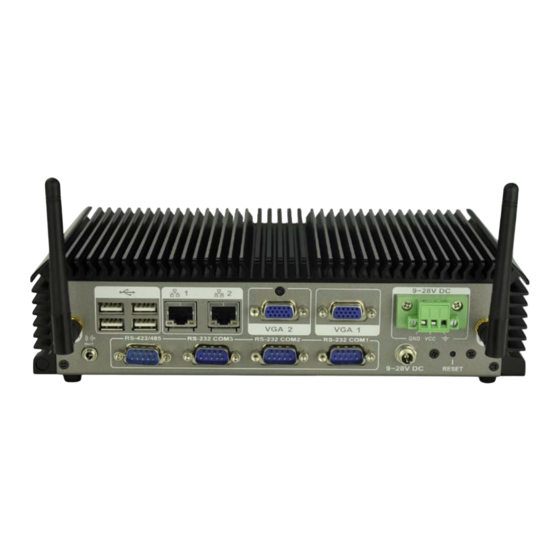
IEI Technology ECN-360A-D2550 User Manual (141 pages)
Embedded System with Intel dual core Atom D2550 Processor, Two VGA, Six USB 2.0, Four COM, GbE and RoHS Compliant
Brand:
IEI Technology
| Category:
Computer Hardware
| Size: 3 MB
Table of Contents
Table of Contents
4
Introduction
12
Overview
13
Model Variations
13
Features
13
Figure 1-1: ECN-360A-D2550
13
Table 1-1: Model Variations
13
Technical Specifications
14
Front Panel
15
Table 1-2: Technical Specifications
15
Rear Panel
16
Figure 1-2: ECN-360A-D2550 Front Panel
16
Figure 1-3: ECN-360A-D2550 Rear Panel
17
Dimensions
18
Figure 1-4: Physical Dimensions (MM)
18
Unpacking
19
Anti - Static Precautions
20
Unpacking Precautions
20
Unpacking Checklist
21
Table 2-1: Package List Contents
22
Installation
23
Installation Precautions
24
Installation and Configuration Steps
24
Hard Disk Drive (Hdd) Installation
24
Figure 3-1: Retention Screws Removal
25
Figure 3-2: HDD Bracket
25
W I -F I Antenna Installation (Wireless Model Only )
26
Figure 3-3: HDD Retention Screws
26
Mount the System
27
Figure 3-4: Wi-Fi Antenna Installation
27
Figure 3-5: Mounting Bracket Retention Screws
27
External Peripheral Interface Connectors
28
Audio Connection
28
LAN Connection
29
Figure 3-6: Audio Connector
29
Serial Port Connection
30
Figure 3-7: LAN Connection
30
USB Device Connection
31
Figure 3-8: DB-9 Serial Port Connector
31
VGA Monitor Connection
32
Figure 3-10: USB Device Connection
32
Figure 3-11: VGA Connector
33
System Motherboard
34
Peripheral Interface Connectors
35
Layout
35
Connectors
35
Figure 4-1: Connectors and Jumpers
35
External Interface Panel Connectors
36
Table 4-1: Peripheral Interface Connectors
36
Table 4-2: Rear Panel Connectors
36
SATA Power Connectors
37
Audio Connector
37
Figure 4-2: 5 V SATA Power Connector Locations
37
Table 4-3: 5 V SATA Power Connector Pinouts
37
Backlight Inverter Connector
38
Figure 4-3: Audio Connector Location
38
Table 4-4: Audio Connector Pinouts
38
Battery Connector
39
Figure 4-4: Backlight Inverter Connector Location
39
Table 4-5: Backlight Inverter Connector Pinouts
39
Digital Input/Output (DIO) Connector
40
Figure 4-5: Battery Connector Location
40
Figure 4-6: Digital I/O Connector Location
40
Table 4-6: Battery Connector Pinouts
40
Fan Connectors
41
Figure 4-7: Fan Connector Locations
41
Table 4-7: Digital I/O Connector Pinouts
41
Table 4-8: Fan Connector Pinouts
41
Front Panel Connector
42
Keyboard/Mouse Connector
42
Figure 4-8: Front Panel Connector Location
42
Table 4-9: Front Panel Connector Pinouts
42
LVDS1 Connector
43
Figure 4-9: Keyboard/Mouse Connector Location
43
Table 4-10: Keyboard/Mouse Connector Pinouts
43
Pcie Mini Card Slots
44
Figure 4-10: LVDS1 Connector Location
44
Table 4-11: LVDS1 Connector Pinouts
44
Figure 4-11: Pcie Mini Card Slot Locations
45
Power Connector (9V~28V)
46
Figure 4-12: Power Connector Location
46
Table 4-12: Pcie Mini Card Slot Pinouts
46
Serial Port Connectors
47
Figure 4-13: RS-232 Serial Port Connector Locations
47
Table 4-13: Power Connector Pinouts
47
Table 4-14: RS-232 Serial Port Connector Pinouts
47
RS-422/485 Serial Port Connector
48
SATA Drive Connectors
48
Figure 4-14: RS-422/485 Connector Location
48
Table 4-15: RS-422/485 Connector Pinouts
48
SO-DIMM Connector
49
Figure 4-15: SATA Drive Connector Locations
49
Table 4-16: SATA Drive Connector Pinouts
49
USB Connector
50
Figure 4-16: SO-DIMM Connector Location
50
Figure 4-17: USB Connector Location
50
Table 4-17: USB Connector Pinouts
50
External Peripheral Interface Connector Panel
51
Ethernet Connectors
51
Figure 4-18: External Peripheral Interface Connector
51
Table 4-18: LAN Pinouts
51
USB Connectors
52
Figure 4-19: RJ-45 Ethernet Connector
52
Table 4-19: RJ-45 Ethernet Connector Leds
52
Table 4-20: USB Port Pinouts
52
VGA Connectors
53
Figure 4-20: VGA Connector
53
Table 4-21: VGA Connector Pinouts
53
Jumper Settings
54
AT/ATX Power Selection Jumper
54
Table 4-22: Jumpers
54
Clear CMOS Jumper
55
Figure 4-21: AT/ATX Power Selection Jumper Location
55
Table 4-23: AT/ATX Power Selection Jumper Settings
55
Table 4-24: Clear CMOS Jumper Settings
55
LVDS1 Voltage Selection
56
Figure 4-22: Clear CMOS Jumper Location
56
Table 4-25: LVDS1 Voltage Selection Jumper Settings
56
Msata/Pcie Mini Selection
57
Figure 4-23: LVDS1 Voltage Selection Jumper Location
57
Figure 4-24: Msata/Pcie Mini Mode Selection Jumper Location
57
Table 4-26: Msata/Pcie Mini Mode Selection Jumper Settings
57
Bios
58
Introduction
59
Starting Setup
59
Using Setup
59
Getting Help
60
Unable to Reboot after Configuration Changes
60
BIOS Menu Bar
60
Table 5-1: BIOS Navigation Keys
60
Main
61
Advanced
62
ACPI Settings
62
RTC Wake Settings
63
CPU Configuration
65
IDE Configuration
66
USB Configuration
67
F81866 Super IO Configuration
68
Serial Port N Configuration
69
F81866 H/W Monitor
73
Smart Fan Mode Configuration
74
Serial Port Console Redirection
75
Iei Feature
77
Chipset
78
Host Bridge Configuration
78
Intel IGD Configuration
79
South Bridge Configuration
81
Boot
82
Security
84
Save & Exit
84
A Safety Precautions
86
Safety Precautions
87
General Safety Precautions
87
Anti-Static Precautions
88
Product Disposal
89
Maintenance and Cleaning Precautions
89
Maintenance and Cleaning
89
Cleaning Tools
90
B Bios Menu Options
91
C One Key Recovery
94
One Key Recovery Introduction
95
Figure C-1: IEI One Key Recovery Tool Menu
95
System Requirement
96
Supported Operating System
97
Setup Procedure for Windows
98
Hardware and BIOS Setup
99
Create Partitions
99
Figure C-2: Launching the Recovery Tool
100
Figure C-3: Recovery Tool Setup Menu
100
Figure C-4: Command Prompt
101
Figure C-5: Partition Creation Commands
102
Install Operating System, Drivers and Applications
103
Building the Recovery Partition
104
Figure C-6: Launching the Recovery Tool
104
Figure C-7: Manual Recovery Environment for Windows
104
Figure C-8: Building the Recovery Partition
105
Figure C-9: Press any Key to Continue
105
Create Factory Default Image
106
Figure C-10: Press F3 to Boot into Recovery Mode
106
Figure C-11: Recovery Tool Menu
106
Figure C-12: about Symantec Ghost Window
107
Figure C-13: Symantec Ghost Path
107
Figure C-14: Select a Local Source Drive
108
Figure C-15: Select a Source Partition from Basic Drive
108
Figure C-16: File Name to Copy Image to
109
Figure C-17: Compress Image
109
Figure C-18: Image Creation Confirmation
110
Figure C-19: Image Creation Complete
110
Figure C-20: Image Creation Complete
110
Auto Recovery Setup Procedure
111
Figure C-21: Press any Key to Continue
111
Figure C-22: Auto Recovery Utility
112
Figure C-23: Launching the Recovery Tool
112
Figure C-24: Auto Recovery Environment for Windows
112
Figure C-25: Building the Auto Recovery Partition
113
Figure C-26: Factory Default Image Confirmation
113
Figure C-27: Image Creation Complete
114
Figure C-28: Press any Key to Continue
114
Setup Procedure for Linux
115
Figure C-29: Partitions for Linux
116
Figure C-30: Manual Recovery Environment for Linux
117
Figure C-31: Access Menu.lst in Linux (Text Mode)
118
Figure C-32: Recovery Tool Menu
118
Recovery Tool Functions
119
Figure C-33: Recovery Tool Main Menu
119
Factory Restore
120
Figure C-34: Restore Factory Default
120
Backup System
121
Figure C-35: Recovery Complete Window
121
Figure C-36: Backup System
121
Restore Your Last Backup
122
Figure C-37: System Backup Complete Window
122
Figure C-38: Restore Backup
122
Manual
123
Figure C-39: Restore System Backup Complete Window
123
Figure C-40: Symantec Ghost Window
123
Restore Systems from a Linux Server through Lan
124
Configure DHCP Server Settings
125
Configure TFTP Settings
126
Configure One Key Recovery Server Settings
127
Start the DHCP, TFTP and HTTP
128
Create Shared Directory
128
Setup a Client System for Auto Recovery
129
Other Information
132
Using AHCI Mode or Ali M5283 / VIA VT6421A Controller
132
System Memory Requirement
134
D Watchdog Timer
135
E Hazardous Materials Disclosure
138
Hazardous Materials Disclosure Table for Ipb Products Certified as R Ohs Compliant under 2002/95/Ec Without Mercury
139
Advertisement
Advertisement
Related Products
IEI Technology ECN-360A-D2550/2G-R10
IEI Technology ECN-360AW-D2550/2G-R10
IEI Technology Enano-8523T
IEI Technology ECN-680A-H61
IEI Technology ECN-360A-ULT3-i5/4G-R10
IEI Technology ECN-360A-ULT3-CE/4G-R10
IEI Technology ECN-360A-HM65
IEI Technology ECN-360A-HM65/4G-R10
IEI Technology ECN-360AW-HM65/4G-R10
IEI Technology ECN-360A-ULT3-CE/WD/4G-R10
IEI Technology Categories
Motherboard
Touch Panel
Computer Hardware
Single board computers
Desktop
More IEI Technology Manuals
Login
Sign In
OR
Sign in with Facebook
Sign in with Google
Upload manual
Upload from disk
Upload from URL