
Subscribe to Our Youtube Channel
Related Manuals for Planet WGS-4215-8P2X


Summary of Contents for Planet WGS-4215-8P2X
- Page 1 Industrial Wall-mount Managed Gigabit Ethernet Switch WGS-4215-8P2X/WGS-4215-8P2XV Quick Installation Guide...
- Page 2 4.1.1 WGS-4215-8P2X/WGS-4215-8P2XV ..........9 4.2 Wall Hanging Installation ............... 10 4.2.1 WGS-4215-8P2X/WGS-4215-8P2XV ..........10 4.3 Magnet Installation ................12 4.3.1 Magnet Installation of WGS-4215-8P2X/WGS-4215-8P2XV ....12 5. Web Login ....................13 5.1 Starting Web Management ..............13 5.2 Saving Configuration via the Web ............17 6.
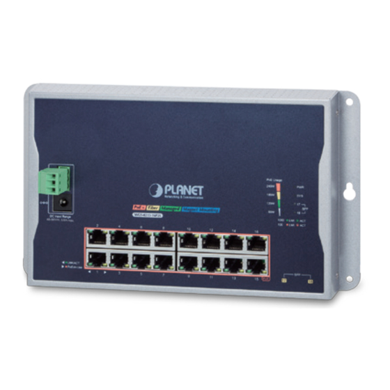
- Page 3 1. Package Contents Thank you for purchasing PLANET Industrial Wall-mount Managed Gigabit Switch, WGS-4215 series. The table below shows the models with the number of ports: Model Name Copper Port Fiber Port LCD Screen WGS-4215-8P2X 8 x 10/100/1000T 2 x 10G...
- Page 4 The Workstations above have been installed with SSH and telnet client soft- ware, such as Tera Term or PuTTY. z A Flat-blade Screwdriver The screwdriver is to facilitate power cable connection to the WGS-4215-8P2X and WGS-4215-8P2XV.
- Page 5 (terminal block) incorporated into customer’s automation network to enhance system reliability and uptime. Power Input Range 4-pin Spring Terminal Block Model WGS-4215-8P2X 48~54V DC WGS-4215-8P2XV 48~54V DC Maximum power requirements also rely on the real site application. WGS-4215-8P2X 4-pin Spring Terminal Block...
- Page 6 Dual power input: Max. 288W PoE budget 3.1 Terminal Block Connector Pinout WGS-4215-8P2X/WGS-4215-8P2XV The Front Panels of the WGS-4215-8P2X and WGS-4215-8P2XV consist of one spring terminal block connector within 4 contacts. Please follow the steps below to insert the power wire.
- Page 7 Insert positive and negative DC power wires into Contacts V1+ and V1- for Power 1, or Contacts V2+ and V2- for Power 2. PWR1 and PWR2 must provide exactly the same DC voltage for power load balance while operating with dual power input. 3.2 Wiring Completed in Three Steps Step 1: Insert the flat-blade screwdriver diagonally into the release hole.
- Page 8 The wire gauge should be in the range from 12 to 16 AWG. 3.3 Wiring the Alarm Contact The alarm contacts are in the middle of the terminal block connector as the picture shows below. Inserting the wires, the Wall-mount Managed Switch will detect the event status of the port or power failure and then form an open circuit.
- Page 9 4. Hardware Installation 4.1 Wall-mount Installation 4.1.1 WGS-4215-8P2X/WGS-4215-8P2XV To install the Wall-mount Managed Switch on the wall, simply follow the following steps: Step 1: Drill 4 holes with 8mm diameter on the wall. The horizontal and vertical distances between the 2 holes are 230mm and 124mm, respectively.
- Page 10 2 3 0 m m 1 2 4 m m 4.2 Wall Hanging Installation 4.2.1 WGS-4215-8P2X/WGS-4215-8P2XV To hang the Wall-mount Managed Switch on the wall, simply follow the following steps: Step 1: Drill two holes, each with a diameter of 8mm, on the wall. The distance between the two holes should be 230mm, and the line connecting them must be horizontal.
- Page 11 Po E+ SF P The installation of the above switch (not an actual picture) is the same as those of the WGS-4215-8P2X and WGS-4215-8P2XV. Make sure the equipment is securely wall-mounted as strong vibration could cause it to drop or break.
- Page 12 The installation of the above switch (not an actual picture) is the same as those of the WGS-4215-8P2X and WGS-4215-8P2XV. Please use the screw from the magnet kit to avoid breaking the device.
- Page 13 5. Web Login 5.1 Starting Web Management The following shows how to start up the Web Management of the Wall-mount Managed Switch. Note the Wall-mount Managed Switch is configured through an Ethernet connection. Please make sure the manager PC must be set to the same IP subnet address.
- Page 14 (1) This device may not cause harmful interference and (2) This device must accept any interference received, including interference that may cause undesired operation. PLANET Technology Corp. Made in Taiwan Figure 5-2: Industrial Managed Switch MAC ID Label Figure 5-3: Web Login Screen...
- Page 15 Log in with "admin" and the “new password” to access the Web interface. Figure 5-5: Web Login with New Password The following web screen is based on the WGS-4215-8P2X. The display of the WGS-4215-8P2X is the same as the WGS-4215-8P2XV.
- Page 16 Figure 5-6: Web Main Screen of Wall-mount Managed Switch The Switch Menu on the top of the Web page lets you access all the commands and statistics the Industrial Managed Switch provides. The Switch Menu always “System”, “Switching”, “QoS”, contains more buttons, such...
- Page 17 5.2 Saving Configuration via the Web In the Wall-mount Managed Switch, the running configuration file stores in the RAM. In the current version, the running configuration sequence of running-config can be saved from the RAM to FLASH by “Save Configurations to FLASH” function, so that the running configuration sequence becomes the startup configuration file, which is called configuration save. To save all applied changes and set the current configuration as a startup configuration, the startup-configuration file will be loaded automatically across a system reboot.
- Page 18 (1) This device may not cause harmful interference and (2) This device must accept any interference received, including interference that may cause undesired operation. PLANET Technology Corp. Made in Taiwan Figure 6-1: Managed Switch MAC ID Label...
- Page 19 Display of the Current IP Address 1. The “#” prompt, enter the following command and press <Enter>. WGS-4215-8P2X# show vlan interface 2. The screen displays the current IP address shown in Figure 6-3 Figure 6-3: IP Information Screen...
- Page 20 4. At the “(config)#” prompt, enter the following command and press <Enter> as shown in Figure 6-4. WGS-4215-8P2X(config)# interface VLAN 1 WGS-4215-8P2X(config-if-vlan)# ip address 192.168.1.100 mask 255.255.255.0 The previous command would apply the following settings for the Wall-mount Managed Switch. IP Address: 192.168.1.100 Subnet Mask: 255.255.255.0...
- Page 21 7. LCD Touch Screen (WGS-4215-8P2XV only) The WGS-4215-8P2XV has a 2.4-inch color LCD touch screen with management functions. Tap the LCD touch screen to wake the LCD touch screen. Figure 7-1: To wake the LCD touch screen The factory default LCD configurations are shown as follows. Default LCD: Enable Default Touch Screen: Enable Default Backlight Timeout: Enable Default Backlight Timeout Time: 300...
- Page 22 You can use the Web management interface and click LCD, and then in the LCD Management, change LCD configuration. Please refer to the user’s manual for more.
- Page 23 5 seconds. After the device is rebooted, you can log in the Web interface management within the same subnet of 192.168.0.xx. Reset Button 100/1G/2.5G/10G Reset Figure 8-1: WGS-4215-8P2X(V) Reset Button...
- Page 24 Thank you for purchasing PLANET products. You can browse our online FAQ resource and User’s Manual on PLANET Web site first to check if it could solve your issue. If you need more support information, please contact PLANET switch support team.
Need help?
Do you have a question about the WGS-4215-8P2X and is the answer not in the manual?
Questions and answers