Advertisement
Quick Links
EN50155
Switch
Q
I
I N D U S T R I A L
uick
nstallation
Introduction
Consisting of three models with different power supply options, the TPS-
141TX-M12 series are unmanaged PoE Ethernet switches with four
10/100Base-T(X) P.S.E. ports and one 10/100Base-T(X) port. Designed for
industrial applications, especially rolling stock, vehicle, and railway
applications, this series boasts EN50155 compliance and M12 connectors
to ensure tight and robust connections, and guarantee reliable operation
against environmental disturbances, such as vibration and shock. The P.S.E.
ports are able to provide sufficient power for those power-hungry devices with
up to 30W per port. Therefore, you can attach an IEEE 802.3at-compliant
device to the switch without requiring additional power. The series supports a
wide operating temperature ranging from -40 C to 75 C, making it an ideal
solution for harsh environments.
Package Contents
The device is shipped with the following items. If any of these items is missing
or damaged, please contact your customer service representative for
assistance.
Contents
Pictures
TPS-141TX-M12 or
TPS-141TX-M12-24V or
TPS-141TX-M12-MV
QIG
Preparation
Before you begin installing the device, make sure you have all of the package
contents available and a PC with Microsoft Internet Explorer 6.0 or later, for
using web-based system management tools.
Safety & Warnings
Elevated Operating Ambient: If installed in a closed environment, make sure
the operating ambient temperature is compatible with the maximum
ambient temperature (Tma) specified by the manufacturer.
Reduced Air Flow: Make sure the amount of air flow required for safe operation
of the equipment is not compromised during installation.
Mechanical Loading: Make sure the mounting of the equipment is not in a
hazardous condition due to uneven mechanical loading.
Circuit Overloading: Consideration should be given to the connection of the
equipment to the supply circuit and the effect that overloading of the circuits
might have on overcurrent protection and supply wiring. Appropriate
consideration of equipment nameplate ratings should be used when addressing
this concern.
Q I G
TPS-141TX-M12 Series
TPS-141TX-M12 Series
G
uide
Dimension
15.0
o
o
40.0
TPS-141TX-M12
Panel Layouts
Number
Front View
1
3
P1
1
4
1
P3
P5
6
Tx+
Rx+
Tx+: PoE Vout+
Tx- : PoE Vout+
Rx+: PoE Vout-
Rx- : PoE Vout-
Rx-
Tx-
TPS-141TX-M12
Installation
Wall-mount
The device can be fixed to the wall. Follow the steps below to install the device on the wall.
Step 1: Hold the
Step 2: Insert four screws through the large opening of the keyhole-shaped apertures at the
top and bottom of the unit and fasten the screw to the wall with a screwdriver.
Step 3: Slide the
1907-2-29-TPS141TXM12-1.2
88.9
88.9
73.9
73.9
44.4
44.4
R2.5
15.0
R4.00
P1
P2
P1
PoE
PoE
P3
P4
P3
PoE
PoE
P5
PWR
P5
FDX
FDX
Tx+
Rx+
V+
Tx+
Rx+
Tx+: PoE Vout+
N.C.
Tx+: PoE Vout+
N.C.
Tx- : PoE Vout+
Tx- : PoE Vout+
N.C.
Rx+: PoE Vout-
Rx+: PoE Vout-
Rx- : PoE Vout-
V-
Rx- : PoE Vout-
Rx-
Tx-
N.C.
Rx-
Tx-
TPS-141TX-M12
TPS-141TX-M12-24V(MV)
55.0
TPS-141TX-M12-24V/ MV
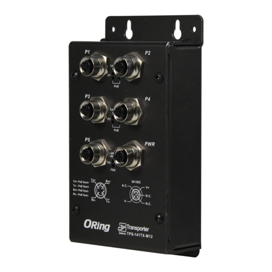
1. Fast Ethernet port (P1 - P4 with PoE support)
P2
2. Power port
3. LNK/ACT LED for Ethernet port
PoE
4. PoE status LED
P4
5. Power status LED
6. Duplex/Collision LED for Ethernet port
PoE
5
PWR
2
FDX
N.C.
V+
N.C.
V-
N.C.
d
evice upright against the wall
d
evice downwards and tighten the four screws for added stability.
Instead of screwing the screws in all the way, it is advised to
leave a space of about 2mm to allow room for sliding the switch
between the wall and the screws.
PRINTED ON RECYCLED PAPER
EN50155 5-port unmanaged
PoE Ethernet switch
Wiring
For pin assignments of power, console and relay output ports, please refer to the following tables.
Grounding
Grounding and wire routing help limit the effects of noise due to electromagnetic interference
(EMI). Run the ground connection from the grounding pin on the power connector to the grounding
surface prior to connecting devices.
R2.5
Power port pinouts
R4.00
P2
The switch provides one set of power supply on a M12 5-pin A-coding
connector. Insert the power cable to the power connector on the
P4
device and rotate the outer ring of the cable connector until a
snug fit is achieved. Make sure the connection is tight.
PWR
V+
N.C.
V-
N.C.
Network Connection
The switch has five 10/100Base-T(X) Ethernet ports in the form of M12 connector. These ports
are PoE-enabled, and thus can deliver power over the same Ethernet cable. Depending on
the link type, the switch uses CAT 3, 4, 5,5e UTP cables to connect to network devices (PCs,
servers, switches, routers, or hubs). Please refer to the following table for cable specifications.
Cable
Type
Max. Length
10BASE-T
Cat. 3, 4, 5 100-ohm
UTP 100 m (328 ft)
100BASE-TX
Cat. 5 100-ohm UTP
UTP 100 m (328 ft)
Pin Definition
M12 D-coding Pin Definition
Pin No.
Description
#1
TX+ with PoE Vout+
#2
RX+ with PoE Vout-
TX- with PoE Vout+
#3
#4
RX- with PoE Vout-
Configurations
After installing the switch and connecting cables, start the
power. The green power LED should turn on. Please refer to the following tablet
for LED indication.
LED
Color
Status
Description
Power
Green
On
Power is on
10/100Base-T(X)
LNK/ACT
Green
On
Port running at 10/100Mbps
Duplex /
On
Full Duplex
Amber
Collision
Blinking
Collision occurs
PoE
Blue
On
Port providing power to PD devices
Version 1.2
N.C.
V+
N.C.
V-
N.C.
Connector
4-pin female M12
D-coding connector
4-pin female M12
D-coding connector
#1
#2
#4
#3
d
evice by turning on
Quick Installation Guide
Advertisement

Related Manuals for ORiNG TPS-141TX-M12 Series


Summary of Contents for ORiNG TPS-141TX-M12 Series
- Page 1 Version 1.2 EN50155 EN50155 5-port unmanaged Switch TPS-141TX-M12 Series I N D U S T R I A L PoE Ethernet switch uick nstallation uide Introduction Dimension Consisting of three models with different power supply options, the TPS- Wiring 141TX-M12 series are unmanaged PoE Ethernet switches with four For pin assignments of power, console and relay output ports, please refer to the following tables.
- Page 2 IEC60068-2-6 Safety EN60950-1 Warranty 5 years Note : HW version 2.0 Copyright© 2015 ORing All rights reserved. ORing Industrial Networking Corp. TEL: +886-2-2218-1066 Website: www.oringnet.com FAX: +886-2-2218-1014 E-mail: support@oringnet.com Q I G Q I G TPS-141TX-M12 Series PRINTED ON RECYCLED PAPER...
Need help?
Do you have a question about the TPS-141TX-M12 Series and is the answer not in the manual?
Questions and answers