Moxa Technologies NPort IA5000A-I/O series User Manual
With digital i/o
Hide thumbs
Also See for NPort IA5000A-I/O series:
- Installation manual (10 pages) ,
- User manual (176 pages) ,
- Quick installation manual (11 pages)
Table of Contents
Advertisement
Quick Links
Download this manual
See also:
Installation Manual
Advertisement
Table of Contents

Related Manuals for Moxa Technologies NPort IA5000A-I/O series


Summary of Contents for Moxa Technologies NPort IA5000A-I/O series
- Page 1 NPort IA5000A-I/O Series NPort IAW5000A-I/O Series User’s Manual Edition 3.0, January 2018 www.moxa.com/product © 2018 Moxa Inc. All rights reserved.
-
Page 2: Copyright Notice
NPort IA5000A-I/O NPort IAW5000A-I/O User’s Manual The software described in this manual is furnished under a license agreement and may be used only in accordance with the terms of that agreement. Copyright Notice © 2018 Moxa Inc. All rights reserved. Trademarks The MOXA logo is a registered trademark of Moxa Inc. -
Page 3: Table Of Contents
Table of Contents Introduction ............................1-1 Overview ............................1-2 Package Checklist ..........................1-2 Product Features ..........................1-2 Getting Started..........................2-1 Overview ............................2-2 Panel Layout ............................2-2 LED Indicators ............................ 2-3 Pull-Up/Down Resistors for RS-422/485....................2-3 Connecting the Hardware........................2-4 Connecting to the Network ...................... - Page 4 WLAN Settings (for the NPort IAW5000A-I/O Series) ............... 7-5 Advanced Settings ........................7-21 Web Console: Serial Port Settings ..................... 8-1 Overview ............................8-2 Serial Port Settings ........................8-2 Communication Parameters ......................8-20 Data Buffering/Log ........................8-22 Web Console: Modbus Address Mapping & I/O Setting ..............9-1 Modbus Address Mapping Table ......................
-
Page 5: Introduction
Introduction The following topics are covered in this chapter: Overview Package Checklist Product Features... -
Page 6: Overview
Per-port offline port buffering and serial data log • 4kV serial surge protection • For NPort IA5000A-I/O Series: 6 or 12 digital I/Os to collect local data for status monitoring Cascading Ethernet ports for easy wiring • For NPort IAW5000A-I/O Series: Link any serial, Digital I/O, or Ethernet device to an IEEE 802.11a/b/g/n network... -
Page 7: Getting Started
Getting Started The following topics are covered in this chapter: Overview Panel Layout LED Indicators Pull-Up/Down Resistors for RS-422/485 Connecting the Hardware Connecting to the Network Connecting the Power Connecting to a Serial Device ... -
Page 8: Overview
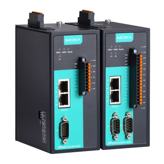
NPort IAW5x50A-6I/O Getting Started Overview This chapter presents the hardware features of the IA5000A-I/O and IAW5000A-I/O and explains how to connect the hardware. Panel Layout Top View Side View Front View and Back View... -
Page 9: Led Indicators
NPort IAW5x50A-6I/O Getting Started LED Indicators Name Color Function PWR 1, PWR 2 Green Power is being supplied to power input PWR1, PWR2. Ready Steady on: Power is on, and the NPort is booting up. Blinking: Indicates an IP conflict, or DHCP or BOOTP server did not respond properly, or a relay output occurred. -
Page 10: Connecting The Hardware
NPort IAW5x50A-6I/O Getting Started Connecting the Hardware ATTENTION Before connecting the hardware, follow these important wiring safety precautions: Disconnect power source Do not install or wire this unit or any attached devices with the power connected. Disconnect the power before installation by removing the power cord before installing and/or wiring your unit. -
Page 11: Connecting To A Serial Device
NPort IAW5x50A-6I/O Getting Started Connecting to a Serial Device Use a serial cable to connect your serial device to a serial port on the NPort. Pin Assignments The IA5000A-I/O and IAW5000A-I/O Series use DB9 serial ports to connect to serial devices. Each port supports three serial interfaces that select by software: RS-232, RS-422, and RS-485 (both 2 and 4-wire). -
Page 12: Di/Do Pinouts
NPort IAW5x50A-6I/O Getting Started DI/DO Pinouts Digital Digital Ground Digital Digital Digital Digital Common Ground Output 0 Output 1 Input 0 Input 1 Input 2 Input 3 I/O Wiring Diagram A dry dontact is a contact that works without a power source. A wet contact is a contact that must work with a power source. -
Page 13: Mounting The Unit
NPort IAW5x50A-6I/O Getting Started Mounting the Unit 1. Connect the power adapter. Connect the 12–48 VDC power line or DIN-rail power supply to the NPort IA5000A-I/O and IAW5000A-I/O devices’ terminal block. 2. Use a serial cable to connect the NPort to a serial device. 3. -
Page 14: Initial Ip Configuration
Initial IP Configuration The following topics are covered in this chapter: Overview Factory Default IP Settings Using ARP to Assign IP Address Using the Telnet Console to Assign IP Address Using the Serial Console to Assign IP Address... -
Page 15: Overview
With the NPort's default setting (Ethernet Bridge function disabled), please ensure the Ethernet cable is connected before powering up the NPort. Then, proceed to following IP configuration options. Factory Default IP Settings NPort IA5000A-I/O Series Network Interface IP Configuration IP Address... -
Page 16: Using The Telnet Console To Assign Ip Address
NPort IAW5x50A-6I/O Initial IP Configuration 5. You will see a message indicating that the connection failed. The NPort will automatically reboot with the new IP address. You can verify that the configuration was successful by connecting to the new IP address with Telnet, ping, the web console, or the DSU. Using the Telnet Console to Assign IP Address 1. - Page 17 NPort IAW5x50A-6I/O Initial IP Configuration 6. Press E or use the cursor keys to select Ethernet and press ENTER. 7. Use the cursor keys to navigate between the different fields. For IP address, Netmask, and Gateway, enter the desired values directly. For IP configuration and LAN speed, press ENTER to open a submenu and select between the available options.
-
Page 18: Using The Serial Console To Assign Ip Address
NPort IAW5x50A-6I/O Initial IP Configuration Using the Serial Console to Assign IP Address Before using the NPort’s serial console, turn off the power and use a serial cable to connect the NPort console port to your computer’s serial port. Port 1 on the NPort serves as the console port. Use Port 1 connecting to the console port with a serial-based terminal or terminal emulator program, such as Windows HyperTerminal. - Page 19 NPort IAW5x50A-6I/O Initial IP Configuration 5. Hold the grave accent key (`) down and power up the NPort. The continuous string of grave accent characters triggers the NPort to switch from data mode to console mode. 6. The serial console will open and will be functionally identical to the Telnet console. Please refer to the Telnet console section for instructions on how to navigate the console and configure the IP settings.
-
Page 20: Introduction To Operation Modes
Introduction to Operation Modes The following topics are covered in this chapter: Overview RealCOM Mode RFC2217 Mode TCP Server Mode TCP Client Mode UDP Mode Pair Connection Modes Ethernet Modem Mode Reverse Terminal Mode... -
Page 21: Overview
NPort IAW5x50A-6I/O Introduction to Operation Modes Overview This chapter introduces the different serial port operation modes that are available on the NPort IA5000A-I/O and IAW5000A-I/O Series. Each serial port on the NPort is configured independently of the other ports, with its own serial communication parameters and operation mode. -
Page 22: Rfc2217 Mode
NPort IAW5x50A-6I/O Introduction to Operation Modes connection, the NPort device server accepts the Ethernet frame, unpacks the TCP/IP packet, and sends the serial data to the appropriate device. ATTENTION In RealCOM mode, several hosts can have simultaneous access control over the NPort serial port. If necessary, you can limit access by using the NPort’s Accessible IP settings. -
Page 23: Tcp Client Mode
NPort IAW5x50A-6I/O Introduction to Operation Modes TCP Client Mode In TCP Client mode, the NPort actively establishes a TCP connection to a specific network host when data is received from the attached serial device. After the data has been transferred, the NPort can automatically disconnect from the host computer through the Inactivity time settings. -
Page 24: Pair Connection Modes
NPort IAW5x50A-6I/O Introduction to Operation Modes Pair Connection Modes Pair Connection Master and Slave modes connect two NPort device servers over a network for serial-to-serial communication. A device attached to one NPort can then communicate transparently to a device attached to the other NPort, as if the two devices were connected by a serial cable. - Page 25 NPort IAW5x50A-6I/O Introduction to Operation Modes necessary or desirable to configure a device by serial console (e.g., for security reasons, when using older-generation equipment, or as a backup configuration method when the network is down). The Reverse Terminal mode is widely used for device management in control rooms. The system waits for a host on the network to initiate a connection.
-
Page 26: Use Real Com Mode To Communicate With Serial Devices
Use Real COM Mode to Communicate with Serial Devices The following topics are covered in this chapter: Overview Device Search Utility Installing the Device Search Utility Find a Specific NPort on the Ethernet Network via the DSU ... -
Page 27: Overview
NPort IAW5x50A-6I/O Use Real COM Mode to Communicate with Serial Devices Overview This chapter will instruct you on how to install the necessary software and provide the steps to mapping virtual COM port to help user's software keep working as usual. 1. - Page 28 NPort IAW5x50A-6I/O Use Real COM Mode to Communicate with Serial Devices 3. Click Next to install program files to the default directory, or click Browse to select an alternate location. 4. Check the checkbox if you want the DSU to create a desktop icon, or just click Next to install the program's shortcuts in the appropriate Start Menu folder.
- Page 29 NPort IAW5x50A-6I/O Use Real COM Mode to Communicate with Serial Devices 5. Click Next to proceed with the installation. The installer then displays a summary of the installation options. 6. Click Install to begin the installation. The setup window will report the progress of the installation. To change the installation settings, click Back and navigate to the previous screen.
-
Page 30: Find A Specific Nport On The Ethernet Network Via The Dsu
NPort IAW5x50A-6I/O Use Real COM Mode to Communicate with Serial Devices Find a Specific NPort on the Ethernet Network via the DSU The Broadcast Search function is used to locate all the NPort device servers that are connected to the same LAN as your computer. -
Page 31: Opening Your Browser
NPort IAW5x50A-6I/O Use Real COM Mode to Communicate with Serial Devices 2. When the search is complete, all the NPort device servers that were located will be displayed in the DSU window. 3. To modify the configuration of the highlighted NPort device servers, click on the Console icon to open the web console. - Page 32 NPort IAW5x50A-6I/O Use Real COM Mode to Communicate with Serial Devices 4. On the first page of the web console, type admin for the default account name and moxa for the default password. ATTENTION If you use other web browsers, remember to Enable the functions to allow cookies that are stored on your computer or allow per-session cookies.
-
Page 33: Configure Operation Mode To Real Com Mode
NPort IAW5x50A-6I/O Use Real COM Mode to Communicate with Serial Devices ATTENTION If you forgot the password, the ONLY way to start configuring the NPort is to load the factory defaults by using the reset button. ATTENTION Remember to export the configuration file when you have finished the configuration. After using the reset button to load the factory defaults, your configuration can be easily reloaded into the NPort by using the Import function. -
Page 34: Nport Windows Driver Manager
NPort IAW5x50A-6I/O Use Real COM Mode to Communicate with Serial Devices NPort Windows Driver Manager Installing the NPort Windows Driver Manager The NPort Windows Driver Manager is intended for use with NPort device server serial ports that are set to Real COM mode. - Page 35 NPort IAW5x50A-6I/O Use Real COM Mode to Communicate with Serial Devices Click Next to install program files to the default directory, or click Browse to select an alternate location. 3. Click Next to install the program’s shortcuts in the appropriate Start Menu folder. 4.
- Page 36 NPort IAW5x50A-6I/O Use Real COM Mode to Communicate with Serial Devices 5. Click Install to begin the installation. The setup window will report the progress of the installation. To change the installation settings, click Back and navigate to the previous screen. The installer will display a message that the software has not passed Windows Logo testing.
-
Page 37: Using Nport Windows Driver Manager
NPort IAW5x50A-6I/O Use Real COM Mode to Communicate with Serial Devices Using NPort Windows Driver Manager After you have installed the NPort Windows Driver Manager, you can set up the NPort device server’s serial ports as remote COM ports for your PC host. Make sure that the serial port(s) on your NPort device server are set to Real COM mode before mapping COM ports with the NPort Windows Driver Manager. - Page 38 NPort IAW5x50A-6I/O Use Real COM Mode to Communicate with Serial Devices 3. Click Search to search for the NPort device servers. From the list that is generated, select the server to which you will map COM ports, and then click OK. 4.
- Page 39 NPort IAW5x50A-6I/O Use Real COM Mode to Communicate with Serial Devices 5. COM ports and their mappings will appear in blue until they are activated. Activating the COM ports saves the information in the host system registry and makes the COM port available for use. The host computer will not have the ability to use the COM port until the COM ports are activated.
- Page 40 NPort IAW5x50A-6I/O Use Real COM Mode to Communicate with Serial Devices 7. Ports that have been activated will appear in black. 8. Use terminal software to open the mapped COM port to communicate with the serial device. You may download PComm Lite, a useful tool to check the serial communication, from Moxa’s website: http://www.moxa.com/support/download.aspx?type=support&id=167 Configure the mapped COM ports with Advanced Functions For Real COM Mode, to reconfigure the settings for a particular serial port on the NPort device server, select the...
- Page 41 NPort IAW5x50A-6I/O Use Real COM Mode to Communicate with Serial Devices 1. On the Basic Setting window, use the COM Number drop-down list to select a COM number to be assigned to the NPort device server’s serial port that is being configured. Select the Auto Enumerating COM Number for Selected Ports option to automatically assign available COM numbers in sequence to selected serial ports.
- Page 42 NPort IAW5x50A-6I/O Use Real COM Mode to Communicate with Serial Devices port. This causes lower throughput. Classical mode is recommended if you want to ensure that all data is sent out before further processing. FIFO If FIFO is Disabled, the NPort device server will transmit one byte each time the Tx FIFO becomes empty, and an Rx interrupt will be generated for each incoming byte.
- Page 43 NPort IAW5x50A-6I/O Use Real COM Mode to Communicate with Serial Devices If you have disabled Fast Flush and find that COM ports mapped to the NPort device server perform markedly slower than when using a native COM port, try to verify if “PurgeComm()” functions are used in your application.
-
Page 44: Linux Real Tty Drivers
NPort IAW5x50A-6I/O Use Real COM Mode to Communicate with Serial Devices 5. The IPv6 Settings function is available only for the NPort 6000 Series. 6. To save the configuration to a text file, select Export from the COM Mapping menu. You will then be able to import this configuration file to another host and use the same COM Mapping settings in the other host. -
Page 45: Hardware Setup
NPort IAW5x50A-6I/O Use Real COM Mode to Communicate with Serial Devices 3. Map the NPort serial port to the host’s tty port Hardware Setup Before proceeding with the software installation, make sure you have completed the hardware installation. Note that the default IP address for the NPort device server is 192.168.127.254, and the default username and password are admin and moxa, respectively. -
Page 46: Removing Mapped Tty Ports
NPort IAW5x50A-6I/O Use Real COM Mode to Communicate with Serial Devices In this example, 16 tty ports will be added, all with IP 192.168.3.4, with data ports from 950 to 965 and command ports from 966 to 981. Mapping tty ports manually To map tty ports manually, you may execute mxaddsvr and manually specify the data and command ports, as in the following example: # cd /usr/lib/npreal2/driver... -
Page 47: Configuring The Unix Driver
NPort IAW5x50A-6I/O Use Real COM Mode to Communicate with Serial Devices 2. Copy moxattyd.tar to the directory you created. If you created the /usr/etc directory above, you would execute the following commands: # cp moxattyd.tar /usr/etc # cd /usr/etc 3. Extract the source files from the tar file by executing the command: # tar xvf moxattyd.tar The following files will be extracted: README.TXT... - Page 48 NPort IAW5x50A-6I/O Use Real COM Mode to Communicate with Serial Devices Adding an additional server 1. Modify the text file moxattyd.cf to add an additional server. Users may use vi or any text editor to modify the file. For more configuration information, look at the file moxattyd.cf, which contains detailed descriptions of the various configuration parameters.
-
Page 49: Web Console: Basic Settings
Web Console: Basic Settings The following topics are covered in this chapter: Overview Basic Settings... -
Page 50: Overview
NPort IAW5x50A-6I/O Web Console: Basic Settings Overview This chapter introduces the NPort web console and explains how to configure the basic settings. The NPort can be configured from anywhere on the network through its web console. Simply point the browser to the device server’s IP address to open the web console. - Page 51 NPort IAW5x50A-6I/O Web Console: Basic Settings ATTENTION If you have forgotten the password, you can use the reset button to load factory defaults, but this will erase all previous configuration information. The web console will appear as shown below. Settings are presented on pages that are organized by folder. Select the desired folder in the left navigation panel to open that page.
-
Page 52: Basic Settings
NPort IAW5x50A-6I/O Web Console: Basic Settings Basic Settings On the Basic Settings page, you can configure: Server Name Default NPortIA5150A-6I/O_<serial no.> or NPort IA5250A-6I/O_<serial no.> NPortIAW5150A-6I/O_<serial no.> or NPort IAW5250A-6I/O_<serial no.> NPortIA5150A-12I/O_<serial no.> or NPort IA5250A-12I/O_<serial no.> NPortIAW5150A-12I/O_<serial no.> or NPort IAW5250A-12I/O_<serial no.> Options free text (e.g., “Server 1”) Description... -
Page 53: Time Zone
NPort IAW5x50A-6I/O Web Console: Basic Settings Time Zone Default (GMT)Greenwich Mean Time Options (GMT)Greenwich Mean Time (GMT-01:00)Azores, Cape Verde Is. (GMT-02:00)Mid-Atlantic etc. Description This field shows the currently selected time zone and allows you to select a different time zone. Local Time Default Options... -
Page 54: Web Console: Network Settings
Web Console: Network Settings The following topics are covered in this chapter: Overview Network Settings General Settings Ethernet/Bridge Settings WLAN Settings Advanced Settings... -
Page 55: Overview
NPort IAW5x50A-6I/O Web Console: Network Settings Overview This chapter explains how to configure all settings located under the Network Settings folder in the NPort web console. Network Settings General Settings On the General Settings page in the Network Settings folder, you can modify DNS server 1 and 2. DNS Server 1 and 2 Default Options... -
Page 56: Ethernet/Bridge Settings
NPort IAW5x50A-6I/O Web Console: Network Settings Ethernet/Bridge Settings To enable the Ethernet-to-Wireless function, go to the Ethernet/Bridge Settings page and enable Ethernet Bridge. Ethernet Bridge (for NPort IAW5000A-I/O Series) Default Disabled Options Enabled / Disabled Description This field specifies whether to enable Ethernet Bridge mode or not. When Ethernet Bridge is enabled, the LAN and WLAN interfaces are bridged together. - Page 57 IP address is assigned by BOOTP server if DHCP server does not respond. BOOTP: IP address is assigned by BOOTP server. IP Address Default 192.168.127.254 for the NPort IA5000A-I/O Series 192.168.126.254 for the NPort IAW5000A-I/O Series' wired RJ45 Ethernet port Options IP address (e.g., “192.168.1.1”) Description This field is for the IP address that will be assigned to your NPort device server.
-
Page 58: Wlan Settings (For The Nport Iaw5000A-I/O Series)
NPort IAW5x50A-6I/O Web Console: Network Settings WLAN Settings (for the NPort IAW5000A-I/O Series) WLAN The WLAN page is located under WLAN Settings in the Network Settings folder. You can modify IP configuration, IP address, Netmask, and Gateway for your WLAN. The NPort IAW5000A-I/O Series supports IEEE 802.11a/b/g/n wireless network interfaces. - Page 59 NPort IAW5x50A-6I/O Web Console: Network Settings Netmask Default 255.255.255.0 Options Netmask setting (e.g., “255.255.0.0”) Description This field is for the subnet mask. A subnet mask represents all of the network hosts at one geographic location, in one building, or on the same local area network. When a packet is sent out over the network, the NPort device server will use the subnet mask to check whether the desired TCP/IP host specified in the packet is on the local network segment.
-
Page 60: Network Type
NPort IAW5x50A-6I/O Web Console: Network Settings Network Type Default Infrastructure Mode Options Infrastructure Mode, Ad-hoc Mode Description This field specifies whether the NPort will operate in Ad-hoc or Infrastructure Mode. For all wireless networking devices, there are two possible modes for communication with another wireless device. -
Page 61: General Settings For Wlan Profile
NPort IAW5x50A-6I/O Web Console: Network Settings General Settings for WLAN Profile The General page is opened through the Profile page, under WLAN Settings in the Network Settings folder. You can type a profile name to help you differentiate one profile from another. It does not affect operation of the NPort. -
Page 62: Profile Name
NPort IAW5x50A-6I/O Web Console: Network Settings In Infrastructure Mode On the General page, you can configure Profile name, RF Type, and input an SSID provided by your WiFi AP. Additional settings are also available depending on whether you select Ad-hoc Mode or Infrastructure Mode. - Page 63 NPort IAW5x50A-6I/O Web Console: Network Settings RF Type Default 802.11b/g for Ad-Hoc Mode. Auto for Infrastructure Mode. Options 802.11b/g only for Ad-Hoc Mode. Auto, 802.11a, 802.11b/g, 802.11a/n, 802.11b/g/n for Infrastructure Mode. Description This field determines which wireless standard will be used by the selected profile. 802.11a, 802.11b/g, 802.11a/n and 802.11b/g/n are supported.
-
Page 64: Site Survey
NPort IAW5x50A-6I/O Web Console: Network Settings Site Survey When you click Site Survey, the device server will scan for all the APs it can find nearby. It shows all the signal strengths between the device server and the APs. You may check the checkbox and click OK to create a profile for the specified AP. - Page 65 NPort IAW5x50A-6I/O Web Console: Network Settings Roaming Threshold Default -70 (Disable) Options numbers Description When the signal strength between the device and the AP is below -70 dBm (the default number), the device server will start to scan for a new AP to establish the connection. Roaming Difference Default 2 (Disable)
-
Page 66: Security Settings For Wlan Profile
NPort IAW5x50A-6I/O Web Console: Network Settings Security Settings for WLAN Profile The Security page is opened through the Profile page, under WLAN Settings in the Network Settings folder. After selecting Ad-hoc or Infrastructure Mode, click [Security] to open the Security page for the selected profile. - Page 67 NPort IAW5x50A-6I/O Web Console: Network Settings In Infrastructure Mode You will need to configure Authentication and Encryption. These settings must match the settings on the wireless device at the other end of the connection (such as the AP). Different settings and options are available depending on how Authentication and Encryption are configured.
- Page 68 NPort IAW5x50A-6I/O Web Console: Network Settings Authentication Default Open System Options Open System, Shared Key, WPA, WPA-PSK, WPA2, WPA2-PSK Description This field specifies how wireless devices will be authenticated. Only authenticated devices will be allowed to communicate with the NPort. If a RADIUS server is used, this setting must match the setting on the RADIUS server.
- Page 69 NPort IAW5x50A-6I/O Web Console: Network Settings Encryption Default Disable Options Disable, WEP, TKIP, AES-CCMP Description This field specifies the type of encryption to use during wireless communication. Different encryption methods are available depending on the Authentication setting. Also, each encryption method has its own set of parameters that may also require configuration. Disable: No encryption is applied to the data during wireless communication.
-
Page 70: Security Settings For Wep Encryption
NPort IAW5x50A-6I/O Web Console: Network Settings Security Settings for WEP Encryption When Encryption is set to WEP on the Security page for the WLAN profile, you will be able to configure WEP key length, WEP key index, and WEP key source. Other settings will be displayed depending on how WEP key source is configured. - Page 71 NPort IAW5x50A-6I/O Web Console: Network Settings WEP Key Format Default ASCII Options ASCII, HEX Description This field is only available if WEP key source is set to “Manual”. It specifies the format you will use to enter the WEP key. WEP Key 1 Through 4 Default Options...
-
Page 72: Eap Method
NPort IAW5x50A-6I/O Web Console: Network Settings When WPA or WPA2 is used for authentication, you will also need to configure EAP method in the Security settings for the WLAN profile. Other settings will also be displayed depending on how EAP method is configured. -
Page 73: Anonymous Username
NPort IAW5x50A-6I/O Web Console: Network Settings Password Default Options free text (e.g., “Password123”) Description This field specifies the password that will be used to gain access to the WLAN. The correct username and password must be provided for access to be granted. Anonymous Username Default Options... -
Page 74: Advanced Settings
NPort IAW5x50A-6I/O Web Console: Network Settings WLAN Log Settings Default Disable Options Disable, Enable Description When the wireless connection between the device server and the AP is not stable, you may enable this function to have more information available for troubleshooting. You may find System Monitoring ... -
Page 75: Web Console: Serial Port Settings
Web Console: Serial Port Settings The following topics are covered in this chapter: Overview Serial Port Settings Communication Parameters Data Buffering/Log... -
Page 76: Overview
NPort IAW5x50A-6I/O Web Console: Serial Port Settings Overview This chapter explains how to configure all settings located under the Serial Port Settings folder in the NPort web console. Serial Port Settings Operation Modes Each serial port on the NPort is configured through the hyperlink below the column of Operating mode. Click the link of Real COM, it will show the Port settings page. -
Page 77: Operation Mode
NPort IAW5x50A-6I/O Web Console: Serial Port Settings Operation Mode Default Real COM Options Real COM, RFC2217, TCP Server, TCP Client, UDP, Pair Connection Master, Pair Connection Slave, Ethernet Modem, Reverse Terminal Description Along with Application, this field specifies the serial port’s operation mode, or how it will interact with network devices. - Page 78 NPort IAW5x50A-6I/O Web Console: Serial Port Settings TCP alive check time Default 7 min Options 0 to 99 min Description This field specifies how long the NPort will wait for a response to “keep alive” packets before closing the TCP connection. The NPort checks connection status by sending periodic “keep alive”...
- Page 79 NPort IAW5x50A-6I/O Web Console: Serial Port Settings Connection goes down Default always high Options always low, always high Description This field specifies what happens to the RTS and DTR signals when the Ethernet connection goes down. For some applications, serial devices need to know the Ethernet link status through RTS or DTR signals sent through the serial port.
- Page 80 NPort IAW5x50A-6I/O Web Console: Serial Port Settings Force transmit Default 0 ms Options 0 to 65535 Description This field controls data packing by the amount of time that elapses between bits of data. 0: If serial data is not received, the NPort will wait indefinitely for additional data. 1 to 65535: If serial data is not received for the specified amount of time, the data that is currently in the buffer will be packed for network transmission.
- Page 81 NPort IAW5x50A-6I/O Web Console: Serial Port Settings TCP Port Default 4001 Options Description This field specifies the TCP port number that the serial port will use to listen to connections, and that other devices must use to contact the serial port. Packet length Default Options...
-
Page 82: Settings For Tcp Server Mode
NPort IAW5x50A-6I/O Web Console: Serial Port Settings Force transmit Default 0 ms Options 0 to 65535 Description This field controls data packing by the amount of time that elapses between bits of data. 0: If serial data is not received, the NPort will wait indefinitely for additional data. 1 to 65535: If serial data is not received for the specified amount of time, the data that is currently in the buffer will be packed for network transmission. - Page 83 NPort IAW5x50A-6I/O Web Console: Serial Port Settings TCP alive check time Default 7 min Options 0 to 99 min Description This field specifies how long the NPort will wait for a response to “keep alive” packets before closing the TCP connection. The NPort checks connection status by sending periodic “keep alive”...
- Page 84 NPort IAW5x50A-6I/O Web Console: Serial Port Settings Ignore jammed IP Default Disable Options Disable, Enable Description This field specifies how an unresponsive IP address is handled when there are simultaneous connections to the serial port. Disable: All transmission will be suspended if one IP address becomes unresponsive. Transmission will only resume when all hosts have responded.
- Page 85 NPort IAW5x50A-6I/O Web Console: Serial Port Settings Delimiter 1 and 2 Default Disabled Options Disabled, Enabled, 00 to FF Description These fields are used to define special delimiter character(s) for data packing. Enable Delimiter 1 to control data packing with a single character; enable both Delimiter 1 and 2 to control data packing with two characters received in sequence.
-
Page 86: Settings For Tcp Client Mode
NPort IAW5x50A-6I/O Web Console: Serial Port Settings Settings for TCP Client Mode When Operation Mode is set to TCP Client on a serial port’s Operation Modes page, you will be able to configure additional settings such as TCP alive check time, Inactivity time, Ignore jammed IP , Destination address 1-4, Designated local port 1-4, Connection control, and Packet length, Delimiter 1, Delimiter 2, Delimiter process, and Force transmit. - Page 87 NPort IAW5x50A-6I/O Web Console: Serial Port Settings Ignore jammed IP Default Disable Options Disable, Enable Description This field specifies how an unresponsive IP address is handled when there are simultaneous connections to the serial port. Disable: All transmission will be suspended if one IP address becomes unresponsive. Transmission will only resume when all hosts have responded.
- Page 88 NPort IAW5x50A-6I/O Web Console: Serial Port Settings Packet length Default Options 0 to 1024 Description This field specifies the maximum amount of data that is allowed to accumulate in the serial port buffer before sending. 0: Packet length is disregarded and data in the buffer will be sent as specified by the delimiter settings or when the buffer is full.
- Page 89 NPort IAW5x50A-6I/O Web Console: Serial Port Settings Force transmit Default 0 ms Options 0 to 65535 Description This field controls data packing by the amount of time that elapses between bits of data. When using this field, make sure that Inactivity time is disabled or set to a larger value. Otherwise the connection may be closed before the data in the buffer can be transmitted.
- Page 90 NPort IAW5x50A-6I/O Web Console: Serial Port Settings Local listen port Default 4001 Options Description This field specifies the UDP port that the NPort listens to and that other devices must use to contact the attached serial device. Packet length Default Options 0 to 1024 Description...
- Page 91 NPort IAW5x50A-6I/O Web Console: Serial Port Settings Force transmit Default 0 ms Options 0 to 65535 Description This field controls data packing by the amount of time that elapses between bits of data. When using this field, make sure that Inactivity time is disabled or set to a larger value. Otherwise the connection may be closed before the data in the buffer can be transmitted.
-
Page 92: Destination Address
NPort IAW5x50A-6I/O Web Console: Serial Port Settings TCP alive check time Default 7 min Options 0 to 99 min Description This field specifies how long the NPort will wait for a response to “keep alive” packets before closing the TCP connection. The NPort checks connection status by sending periodic “keep alive”... -
Page 93: Settings For Reverse Terminal Mode
NPort IAW5x50A-6I/O Web Console: Serial Port Settings TCP alive check time Default 7 min Options 0 to 99 min Description This field specifies how long the NPort will wait for a response to “keep alive” packets before closing the TCP connection. The NPort checks connection status by sending periodic “keep alive”... -
Page 94: Communication Parameters
NPort IAW5x50A-6I/O Web Console: Serial Port Settings Inactivity time Default 0 ms Options 0 to 65535 ms Description This field specifies the time limit for keeping the connection open if no data flows to or from the serial device. 0: The connection will remain open even if data is never received. For many applications, the serial device may be idle for long periods of time, so 0 is an appropriate setting. -
Page 95: Baud Rate
NPort IAW5x50A-6I/O Web Console: Serial Port Settings Alias Default Options free text (e.g., “Secondary console connection”) Description This is an optional free text field to help you differentiate one serial port from another. It does not affect operation of the NPort device server. ATTENTION Serial communication settings should match the attached serial device. -
Page 96: Data Buffering/Log
NPort IAW5x50A-6I/O Web Console: Serial Port Settings Data Buffering/Log On the serial port’s Data Buffering/Log page, you can enable or disable Port buffering and Serial data logging. Port buffering Default Disable Options Enable, Disable Description This field specifies whether the serial port will use port buffering when the network connection (Ethernet or WLAN) is down. -
Page 97: Web Console: Modbus Address Mapping & I/O Setting
Web Console: Modbus Address Mapping & I/O Setting The following topics are covered in this chapter: Modbus Address Mapping Table User-Defined Modbus Addressing Default Modbus Address I/O Settings DI Channels DO Channels... -
Page 98: Modbus Address Mapping Table
NPort IAW5x50A-6I/O Web Console: Modbus Address Mapping & I/O Setting Modbus Address Mapping Table User-Defined Modbus Addressing The NPort IA5000A-I/O and NPort IAW5000A-I/O Series play a role as the Modbus TCP slave and input and output addresses can be configured on this page. Select the Enable User-defined Modbus Addressing checkbox, and then configure the start address of each Modbus function. -
Page 99: I/O Settings
NPort IAW5x50A-6I/O Web Console: Modbus Address Mapping & I/O Setting I/O Settings DI Channels The status of each DI (digital input) channel appears on the DI Channel Settings page. You can also configure each channel’s digital input mode and parameters by clicking on the channel. DI channels can operate in DI mode or Event Counter mode. -
Page 100: Do Channels
NPort IAW5x50A-6I/O Web Console: Modbus Address Mapping & I/O Setting Save Counter On Power Failure: The NPort IA5000A-I/O and IAW5000A-I/O will automatically save the counter value when there is a power failure if this function is selected. Reset Counter: Select this function to reset the counter. You can apply the DI settings to all DI Channels by selecting the Apply to all DI Channels checkbox. - Page 101 NPort IAW5x50A-6I/O Web Console: Modbus Address Mapping & I/O Setting If you select Pulse Output mode, you can specify the ON Width and OFF Width to generate a square wave. Pulse width unit = 25ms, range = 1-65535. When configuring individual channels, if Power On Setting is selected, the pulse output will start as soon as the NPort is powered on.
-
Page 102: Web Console: System Management
Web Console: System Management The following topics are covered in this chapter: Overview System Management Misc. Network Settings Auto Warning Settings Maintenance Certificate... -
Page 103: Overview
NPort IAW5x50A-6I/O Web Console: System Management Overview This chapter explains how to configure all settings located under the System Management folder in the NPort web console. System Management Misc. Network Settings Accessible IP List The Accessible IP List page is located under Misc. Network Settings in the System Management folder. This page is used this restrict access to the NPort by IP address. -
Page 104: Snmp Agent Settings
NPort IAW5x50A-6I/O Web Console: System Management Refer to the following table for more configuration examples. Desired IP Range IP Address Field Netmask Field Any host Disable Disable 192.168.1.120 192.168.1.120 255.255.255.255 192.168.1.1 to 192.168.1.254 192.168.1.0 255.255.255.0 192.168.0.1 to 192.168.255.254 192.168.0.0 255.255.0.0 192.168.1.1 to 192.168.1.126 192.168.1.0 255.255.255.128... -
Page 105: Read Community String
NPort IAW5x50A-6I/O Web Console: System Management Location Default Options free text (e.g., “Building XYZ”) Description This is an optional free text field that can be used to specify the location for SNMP agents such as the NPort. Read Community String Default public Options... -
Page 106: User Table
NPort IAW5x50A-6I/O Web Console: System Management Read/Write Authentication Mode Default Disable Options Disable, MD5, SHA Description This field specifies the type of authentication to use for read/write access. Read/Write Password Default Options free text (e.g., “password123”) Description This field specifies the password that users must enter for read/write access, if read only authentication is enabled. -
Page 107: Authentication Server
NPort IAW5x50A-6I/O Web Console: System Management Authentication Server RADIUS server: If you are using a RADIUS server for user authentication, enter its IP address here. RADIUS key: If you are using a RADIUS server for user authentication, enter its password here. UDP port (default=1645): If you are using a RADIUS server, enter its UDP port assignment here. -
Page 108: Auto Warning Settings
NPort IAW5x50A-6I/O Web Console: System Management This is where you select the type of events that will be logged by the NPort. Group Event System System Cold Start, System Warm Start Network DHCP/BOOTP Get IP/Renew, Mail Fail, NTP Connect Fail, IP Conflict, Network Link Down, Modbus/TCP Disconnect, Safe Mode Activated Config Login Fail, IP Changed, Password Changed, Firmware Upgrade, SSL Certificate Import,... -
Page 109: Serial Event Settings
NPort IAW5x50A-6I/O Web Console: System Management Serial Event Settings The Serial Event Settings page is located under Auto Warning Settings in the System Management folder. This is where you specify how the NPort will notify you of DCD and DSR events for each serial port. Mail refers to sending an e-mail to a specified address. - Page 110 NPort IAW5x50A-6I/O Web Console: System Management E-mail Alert The E-mail Alert page is located under Auto Warning Settings in the System Management folder. This is where you specify how and where e-mail is sent when e-mail is used for automatic notification of system and serial port events.
-
Page 111: Snmp Trap
NPort IAW5x50A-6I/O Web Console: System Management SNMP Trap The SNMP Trap page is located under Auto Warning Settings in the System Management folder. This is where you specify the SNMP trap settings to use for automatic notification of system and serial port events. SNMP Trap Server IP Default Options... -
Page 112: Maintenance
NPort IAW5x50A-6I/O Web Console: System Management Maintenance Console Settings The Console Settings page is located under Maintenance in the System Management folder. This is where you enable or disable access to the various NPort configuration consoles, as well as the behavior of the reset button. -
Page 113: Reset Button
NPort IAW5x50A-6I/O Web Console: System Management Reset Button Default Always Enable Options Always Enable, Disable after 60 sec Description This field specifies the behavior of the hardware reset button. Always Enable: The reset button will be operate as usual. Disable after 60 sec: The reset button will only be effective for the first 60 seconds that the NPort is powered on. - Page 114 NPort IAW5x50A-6I/O Web Console: System Management Pre-Shared Key The device server can share or back up its configuration by exporting all settings to a file, which can then be imported into another device server. The exported file will be encrypted by a pre-shared key by the user. (The default cipher key is moxa) Configuration Import The Configuration Import page is located under Maintenance in the System Management folder.
-
Page 115: Load Factory Default
NPort IAW5x50A-6I/O Web Console: System Management Configuration Export The Configuration Export page is located under Maintenance in the System Management folder. This is where you can save the NPort’s current configuration to a file on the local host. Click [Export] to begin the process. -
Page 116: Change Password
NPort IAW5x50A-6I/O Web Console: System Management Change Password The Change Password page is located under Maintenance in the System Management folder. To change the password, choose the account name first, and then enter the old password in the Old password field. Leave this blank if the NPort is not currently password-protected. -
Page 117: Certificate
NPort IAW5x50A-6I/O Web Console: System Management Auto load SD card’s configurations when system boots up: By checking this option, the NPort will import the configuration file saved in the SD card to the NPort device when the system boots up. Click [Activate] to submit the change. - Page 118 NPort IAW5x50A-6I/O Web Console: System Management The Ethernet SSL Certificate Import page is located under Certificate in the System Management folder. This is where you can load the Ethernet SSL certificate. Select or browse for the certificate file in the Select SSL certificate/key file field.
- Page 119 NPort IAW5x50A-6I/O Web Console: System Management WPA Server Certificate Import (for the NPort IAW5000A-I/O Series) The WPA Server Certificate Import page is located under Certificate in the System Management folder. This is where you can load the WPA server certificate. Select or browse for the certificate file in the Select WPA server certificate file field.
- Page 120 NPort IAW5x50A-6I/O Web Console: System Management WPA User Key Import (for the NPort IAW5000A-I/O Series) The WPA User Key Import page is located under Certificate in the System Management folder. This is where you can load the WPA user certificate. Select or browse for the user private key file in the Select WPA user privacy key file field and enter the Password for the private key.
- Page 121 NPort IAW5x50A-6I/O Web Console: System Management Certificate/Key Delete The Certificate/Key Delete page is located under Certificate in the System Management folder. This page is where you can delete certificates or WPA keys that have been installed on the model. When you click [Submit], any certificate or key that has been set to “Delete”...
-
Page 122: Web Console: System Monitoring
Web Console: System Monitoring The following topics are covered in this chapter: Overview System Monitoring Serial Status System Status... -
Page 123: Overview
NPort IAW5x50A-6I/O Web Console: System Monitoring Overview This chapter explains how to use the System Monitoring functions on the NPort web console. These functions allow you to monitor many different aspects of operation. System Monitoring Serial Status Serial to Network Connections The Serial to Network Connections page is located under Serial Status in the System Monitoring folder. -
Page 124: Serial Port Error Count
NPort IAW5x50A-6I/O Web Console: System Monitoring The Serial Port Status page is located under Serial Status in the System Monitoring folder. On this page, you can monitor the signal and data transmission status for each serial port. TxCnt: number of Tx packets (to device) for the current connection RxCnt: number of Rx packets (from device) for the current connection TxTotalCnt: number of Tx packets since the NPort was powered on RxTotalCnt: number of Rx packets since the NPort was powered on... -
Page 125: System Status
NPort IAW5x50A-6I/O Web Console: System Monitoring System Status Network Connections The Network Connections page is located under System Status in the System Monitoring folder. On this page, you can view the current status of any network connection to the NPort. Serial Data Log Data logs for each serial port can be viewed in ASCII or HEX format. - Page 126 NPort IAW5x50A-6I/O Web Console: System Monitoring The Serial Data Log page is located under System Status in the System Monitoring folder. This is where you can download the current data log for a serial port. Select the desired serial port in the Select port field. Select the desired data format in the Download format field.
-
Page 127: System Log
NPort IAW5x50A-6I/O Web Console: System Monitoring System Log The System Log page is located under System Status in the System Monitoring folder. This is where you can view the log of NPort system events. Click [Clear log] to clear the log contents. Click [Refresh] to refresh the log contents. - Page 128 NPort IAW5x50A-6I/O Web Console: System Monitoring to save the log to a txt file for an engineer to troubleshoot, e.g., Moxa’s Technical Support Team. Click [Refresh] to refresh the log contents. WLAN Status (for NPort IAW5000A-I/O Series) The WLAN Status page is located under System Status in the System Monitoring folder. This is where you can view the current WLAN settings and status.
-
Page 129: Web Console: Restart
Web Console: Restart The following topics are covered in this chapter: Overview Restart Restart System Restart Ports... -
Page 130: Overview
NPort IAW5x50A-6I/O Web Console: Restart Overview This chapter explains how to use save your configuration changes and restart the NPort using the NPort web console. Configuration changes will not be effective until they are saved and the NPort is rebooted. Restart Restart System The Restart System page is located in the Restart folder. -
Page 131: Restart Ports
NPort IAW5x50A-6I/O Web Console: Restart Restart Ports The Restart Ports page is located in the Restart folder. Select the desired serial and click [Select All] to select all serial ports. Click [Submit] to restart the selected serial ports. 12-3... -
Page 132: Android Api Instructions
Android API Instructions The following topics are covered in this chapter: Overview How to Start MxNPortAPI MxNPortAPI Function Groups Example Program... -
Page 133: Overview
NPort IAW5x50A-6I/O Android API Instructions Overview If you want to remote control your serial devices on an Android platform, then the MxNPortAPI is a simple application programming tool that you can use. The MxNPortAPI helps programmers develop an Android application to access the device server by TCP/IP. The MxNPortAPI provides frequently used serial command sets like port control, input/output, etc., and the style of developed Android application is similar to MOXA Driver Manager. -
Page 134: Mxnportapi Function Groups
NPort IAW5x50A-6I/O Android API Instructions For more details about the installation, please refer to the Overview section. MxNPortAPI Function Groups The supported functions in this API are listed below: Port Control Input/Output Port Status Inquiry Miscellaneous open read getBaud setBreak close write getFlowCtrl... - Page 135 NPort IAW5x50A-6I/O Android API Instructions byte[] buf = {'H','e','l','l','o',' ','W','o','r','l','d'}; mxNPort.open(); /*open port*/ mxNPort.setIoctlMode(mode); /*serial parameters setting*/ mxNPort.write(buf, buf.length); /*write data*/ mxNPort.close(); /*close port*/ } catch (MxException e){ /*Error handling*/ thread.start(); 13-4...
-
Page 136: Snmp Agents With Mib Ii & Rs-232-Like Groups
SNMP Agents with MIB II & RS-232-Like Groups The NPort has built-in SNMP (Simple Network Management Protocol) agent software that supports SNMP Trap, RFC1317 RS-232 like groups and RFC 1213 MIB-II. The following table lists the standard MIB-II groups, as well as the variable implementation for the NPort. -
Page 137: Icmp Mib
NPort IAW5x50A-6I/O SNMP Agents with MIB II & RS-232-Like Groups ICMP MIB IcmpInMsgs IcmpInTimestamps IcmpOutRedirects IcmpInErrors IcmpTimest ampReps IcmpOutEchos IcmpInDestUnreachs IcmpInAddrMasks IcmpOutEchoReps IcmpInTimeExcds IcmpOutMsgs IcmpOutTimestamps IcmpInParmProbs IcmpOutErrors IcmpOutTimestampReps IcmpInSrcQuenchs IcmpOutDestUnreachs IcmpOutAddrMasks IcmpInRedirects IcmpOutTimeExcds IcmpOutAddrMaskReps IcmpInEchos IcmpOutParmProbs IcmpInEchoReps IcmpOutSrcQuenchs UDP MIB UdpInDatagrams UdpOutDatagrams UdpNoPorts... -
Page 138: Rfc1317: Rs-232 Mib Objects
NPort IAW5x50A-6I/O SNMP Agents with MIB II & RS-232-Like Groups RFC1317: RS-232 MIB Objects Generic RS-232-like Group rs232Number RS-232-like General Port Table rs232PortTable rs232PortEntry rs232PortIndex rs232PortType rs232PortInSigNumber rs232PortOutSigNumber rs232PortInSpeed rs232PortOutSpeed RS-232-like Asynchronous Port Group rs232AsyncPortTable rs232AsyncPortIndex rs232AsyncPortStopBits rs232AsyncPortEntry rs232AsyncPortBits rs232AsyncPortParity The Input Signal Table rs232InSigTable rs232InSigPortIndex... -
Page 139: Well-Known Port Numbers
Well-Known Port Numbers Listed below are well-known port numbers that may cause network problems if they are assigned to an NPort serial port. Refer to RFC 1700 for well-known port numbers or refer to the following introduction from IANA. The port numbers are divided into three ranges: Well-Known Ports, Registered Ports, and Dynamic and/or Private Ports. - Page 140 NPort IAW5x50A-6I/O Well-Known Port Numbers UDP Socket Application Service reserved Management Utility Echo Discard Active Users (systat) Daytime Any private printer server Resource Location Protocol Host name server (names server) Whois (nickname) Login Host Protocol (Login) Domain Name Server (domain) Trivial Transfer Protocol (TETP) Gopher Protocol Finger Protocol...
-
Page 141: Ethernet Modem Commands
Ethernet Modem Commands A serial port on the NPort can be set to Ethernet Modem mode, allowing a PC or device to connect to the NPort as if it was an Ethernet modem. This section provides additional detail about how the NPort operates in Ethernet Modem mode. -
Page 142: At Commands
NPort IAW5x50A-6I/O Ethernet Modem Commands AT Commands Ethernet Modem mode supports the following common AT commands, as used with a typical modem: Command Description Remarks Answer manually Dial up specified IP address and port number ATD 192.168.1.1:950 (example) ATE0=Echo OFF ATE1=Echo ON (default) ATH0=On-hook (default) ATH1=Off-hook... -
Page 143: S Registers
NPort IAW5x50A-6I/O Ethernet Modem Commands S Registers Register Description Remarks Ring to auto-answer (default=0) Ring counter (always=0) no action applied Escape code character (default=43 ASCII “+”) Return character (default=13 ASCII) Line feed character (default=10 ASCII) Backspace character (default= 8 ASCII) Wait time for dial tone (always=2, unit=sec) no action applied Wait time for carrier (default=3, unit=sec) -
Page 144: Federal Communication Commission Interference Statement
Federal Communication Commission Interference Statement This equipment has been tested and found to comply with the limits for a Class B digital device, pursuant to Part 15 of the FCC Rules. These limits are designed to provide reasonable protection against harmful interference in a residential installation. - Page 145 NPort IAW5x50A-6I/O Federal Communication Commission Interference Statement Information for the OEMs and Integrators The following statement must be included with all versions of this document supplied to an OEM or integrator, but should not be distributed to the end user. 1.
Need help?
Do you have a question about the NPort IA5000A-I/O series and is the answer not in the manual?
Questions and answers