Sign In
Upload
Manuals
Brands
Tektronix Manuals
Portable Generator
HDLG7
Tektronix HDLG7 Manuals
Manuals and User Guides for Tektronix HDLG7. We have
1
Tektronix HDLG7 manual available for free PDF download: User Manual
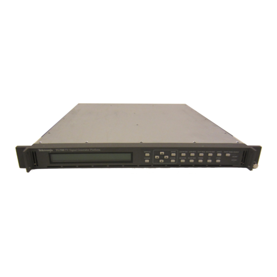
Tektronix HDLG7 User Manual (343 pages)
TV Signal Generator Platform
Brand:
Tektronix
| Category:
Portable Generator
| Size: 7 MB
Table of Contents
Table of Contents
9
List of Tables
16
General Safety Summary
18
Service Safety Summary
20
Compliance Information
21
EMC Compliance
21
Safety Compliance
22
Environmental Considerations
24
About this Manual
25
Preface
25
Products
25
Related Manuals
26
Getting Started
27
Product Description
29
Mainframe Memory Requirements
30
Accessories
31
Options
31
Table 1-1: Standard and Optional Accessories
31
Table 1-2: Instrument and Module Options
31
Initial Product Inspection
33
Mainframe Installation
33
Figure 1-1: Installing the Rackmount Hardware
34
Figure 1-2: Placing the TG700 in the Rack
35
Table 1-3: TG700 Environmental Requirements
35
Table 1-4: AC Line Power Requirements
36
Module Installation and Removal
37
Figure 1-3: TG700 Slot Numbering
38
Figure 1-4: Removing the Blank Panel
39
Figure 1-5: Installing the Module
39
Figure 1-6: Securing the Module
40
Figure 1-7: Removing the Module
41
Functional Checks
41
Operating Basics
67
Figure 2-1: TG700 Front Panel
69
Front-Panel Controls
69
Figure 2-2: TG700 Rear Panel
71
Rear-Panel Connectors
71
Figure 2-3: AG7 Module Connectors
72
Figure 2-4: Location of J452 on the AG7 Module
73
Figure 2-5: AGL7 Module Connectors
73
Figure 2-6: Location of J040 and J960 on the AGL7 Module
75
Figure 2-7: ATG7 Module Connectors
75
Figure 2-8: AVG7 Module Connectors
76
Figure 2-9: AWVG7 Module Connectors
76
Figure 2-10: BG7 Module Connectors
77
Figure 2-11: DVG7 Module Connectors (Option BK)
77
Figure 2-12: GPS7 Module Connectors
78
Table 2-1: GPS7 Module LTC/GPI Connector Pin Assignments
79
Figure 2-13: HD3G7 Module Connectors
80
Figure 2-14: HDLG7 Module Connectors
81
Figure 2-15: HDVG7 Module Connectors (Option BK)
81
Frame Reset Signals
82
Clock Conflict Messages
83
Fan Failure Warning Message
84
Figure 2-16: Mainframe Main Menu
85
Using the Mainframe Menus
85
Figure 2-17: PRESET Submenu
87
Figure 2-18: SEQUENCE Submenu
88
Figure 2-19: FRAME RESET STATUS Submenu
89
Figure 2-20: UTILITY Submenu
90
Figure 2-21: SIGNAL KEY ASSIGN Submenu
92
Figure 2-22: NETWORK INFORMATION Submenu
93
Figure 2-23: NETWORK SETUP Submenu
94
Figure 2-24: DIAGNOSTICS Submenu
96
Figure 2-25: Internal Frequency Calibration Menu
97
Figure 2-26: Gain Calibration Menu
97
Connecting to a Network
98
Figure 2-27: Pin Connections for a 10BASE-T Crossover Ethernet Cable
98
Using the Mainframe General Purpose Interface (GPI)
100
Figure 2-28: Top Cover Removal
101
Figure 2-29: Location of the Mainframe GPI Connectors on the A10 MAIN Board
101
Figure 2-30: Applying the Mainframe GPI Label to the Rear Panel
102
Table 2-2: Mainframe GPI Jumper Settings on the A10 MAIN Board
102
Table 2-3: Pin Assignments of the 10 BASE-T Connector for the Mainframe GPI
103
Table 2-4: Signal Level Combinations and the Corresponding Preset for the Mainframe GPI
103
Figure 2-31: Mainframe GPI ALARM Menu
105
Inspection and Cleaning
109
Table 2-5: External Inspection Check List
109
AG7 Audio Generator Module
113
Product Description
113
AG7 Module Main Menu
114
Operating Procedure
114
Factory Default Settings
117
Table 3-1: AG7 Module Factory Default Settings
117
AGL7 Analog Genlock Module
119
Product Description
119
Operating Procedure
120
AGL7 Module Main Menu
121
Table 3-2: Timing Adjustment Ranges for AGL7 Input Signals
127
Table 3-3: Timing Adjustment Ranges for AGL7 Output Signals
128
Factory Default Settings
129
Table 3-4: AGL7 Module Factory Default Settings
129
ATG7 Analog Test Generator
130
Product Description
130
Operating Procedure
131
Selecting an Output Signal
132
Table 3-5: ATG7 Signal Sets Assigned to the Test Signal Buttons
133
ATG7 Module Main Menu
134
Table 3-6: Test Signals in the ATG7 SELECT SIGNAL Submenu
136
Factory Default Settings
141
Table 3-7: ATG7 Module Factory Default Settings
141
AVG7 Analog Video Generator
142
Product Description
142
Operating Procedure
143
Selecting an Output Signal
144
Table 3-8: AVG7 Signal Sets Assigned to the Test Signal Buttons
145
AVG7 Module Main Menu
148
Factory Default Settings
160
Table 3-9: AVG7 Module Factory Default Settings
160
AWVG7 Analog Wideband Video Generator
161
Product Description
161
Operating Procedure
162
Selecting an Output Signal
163
Table 3-10: AWVG7 Signal Set Assigned to the Test Signal Buttons
164
AWVG7 Module Main Menu
165
Table 3-11: Timing Adjustment Ranges for AWVG7 Module Output Signals
173
Factory Default Settings
176
Table 3-12: AWVG7 Module Factory Default Settings
176
BG7 Black Generator
177
Product Description
177
BG7 Module Main Menu
178
Operating Procedure
178
Table 3-13: BG7 Module Signals for each Signal Format
180
Factory Default Settings
184
Table 3-14: BG7 Module Factory Default Settings
184
DVG7 Digital Video Generator
186
Product Description
186
Operating Procedure
187
Selecting an Output Signal
187
Table 3-15: DVG7 Module Signal Set Assigned to the Test Signal Buttons
189
DVG7 Module Main Menu
191
Factory Default Settings
206
Table 3-16: DVG7 Module Factory Default Settings
206
GPS7 GPS Synchronization and Timecode Module
208
Product Description
208
Operating Procedure
209
Configure the GPS7 Module
210
GPS7 Module Main Menu
222
Table 3-18: GPS7 Module Output Signal Formats
230
Table 3-19: LTC Output Signal Formats
246
Factory Default Settings
250
Table 3-20: GPS7 Module Factory Default Settings
250
HD3G7 HD 3 Gb/S SDI Video Generator
253
Product Description
253
Operating Procedure
254
Selecting an Output Signal
255
Table 3-21: HD3G7 Generator Mode - Level a (1920 × 1080)
255
Table 3-22: HD3G7 Generator Mode - Level B (1920 × 1080)
255
Table 3-23: HD3G7 Generator Mode - Level B (2K × 1080)
256
Table 3-24: HD3G7 Generator Mode - Level a (2K × 1080)
256
Table 3-25: HD3G7 Generator Mode - Level B (2×HD 1920 × 1080)
256
Table 3-26: HD3G7 Converter Mode - Level a 1920 × 1080 Formats
256
Table 3-27: HD3G7 Converter Mode - Level B (1920 × 1080)
257
Table 3-28: HD3G7 Converter Mode - Level B (2×HD 1920 × 1080)
257
Table 3-29: HD3G7 Module Test Signal Set Assigned to the Test Signal Buttons
260
Zone Plate Signals
261
Zone Plate Pattern Control Parameters
264
Zone Plate Dependent Parameters
266
Using Zone Plate Signals
272
HD3G7 Module Main Menu
273
Factory Default Settings
298
HDLG7 HD Dual Link Video Generator
301
Product Description
301
Operating Procedure
302
Selecting an Output Signal
303
HDLG7 Module Main Menu
309
Factory Default Settings
314
HDVG7 HDTV Digital Video Generator
315
Product Description
315
Operating Procedure
316
Selecting an Output Signal
317
HDVG7 Module Main Menu
319
Factory Default Settings
334
Index
337
Advertisement
Advertisement
Related Products
Tektronix HDVG1
Tektronix HFS 9010
Tektronix HFS 9000
Tektronix HFS9DG1
Tektronix HFS9DG2
Tektronix HDST1 HD-SDI
Tektronix HFS 9003
Tektronix HC100
Tektronix H
Tektronix HFS 9009
Tektronix Categories
Test Equipment
Measuring Instruments
Amplifier
Portable Generator
Printer
More Tektronix Manuals
Login
Sign In
OR
Sign in with Facebook
Sign in with Google
Upload manual
Upload from disk
Upload from URL