Table of Contents
Advertisement
Quick Links
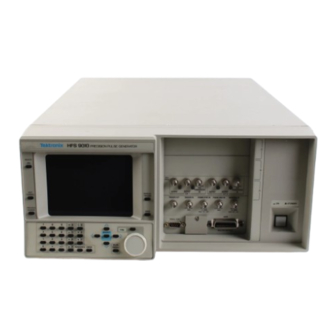
Tektronix HFS 9010
Precision Pulse Generator
A l l t r a d e m a r k s , b r a n d n a m e s , a n d b r a n d s a p p e a r i n g h e r e i n a r e t h e p r o p e r t y o f t h e i r r e s p e c t i v e o w n e r s .
• C r i t i c a l a n d e x p e d i t e d s e r v i c e s
• I n s t o c k / R e a d y - t o - s h i p
Artisan Scientific Corporation dba Artisan Technology Group is not an affiliate, representative, or authorized distributor for any manufacturer listed herein.
$
3250
.00
In Stock
Qty Available: 1
Used and in Excellent Condition
Open Web Page
https://www.artisantg.com/64166-1
• We b u y y o u r e x c e s s , u n d e r u t i l i z e d , a n d i d l e e q u i p me n t
• F u l l - s e r v i c e , i n d e p e n d e n t r e p a i r c e n t e r
Advertisement
Table of Contents

Related Manuals for Tektronix HFS 9010


Summary of Contents for Tektronix HFS 9010
- Page 1 Tektronix HFS 9010 Precision Pulse Generator 3250 In Stock Qty Available: 1 Used and in Excellent Condition Open Web Page https://www.artisantg.com/64166-1 A l l t r a d e m a r k s , b r a n d n a m e s , a n d b r a n d s a p p e a r i n g h e r e i n a r e t h e p r o p e r t y o f t h e i r r e s p e c t i v e o w n e r s .
- Page 2 User Manual HFS 9000 Stimulus System 070-8365-03 Please check for change information at the rear of this manual.
- Page 3 Copyright Tektronix, Inc. 1994. All rights reserved. Tektronix products are covered by U.S. and foreign patents, issued and pending. Information in this publication supercedes that in all previously published material. Specifications and price change privileges reserved. Printed in the U.S.A.
- Page 4 WARRANTY Tektronix warrants that this product will be free from defects in materials and workmanship for a period of one (1) year from the date of shipment. If any such product proves defective during this warranty period, Tektronix, at its option, either will repair the defective product without charge for parts and labor, or will provide a replacement in exchange for the defective product.
- Page 6 Table of Contents General Safety Summary ........Preface .
-
Page 7: Table Of Contents
Table of Contents Syntax Diagrams ..........3–20 Commands . - Page 8 Table of Contents Instrument Setup ..........F–13 Output Level Checks (HFS 9DG1 Card Only) .
- Page 9 Table of Contents List of Figures Figure 1–1: MAIN MENU Button Location ..... 1–2 Figure 1–2: Main Menu Display ......1–3 Figure 1–3: The SELECT and Arrow Buttons .
-
Page 10: Figure 1-4: The Save/Recall Menu
Table of Contents Figure 2–22: The Data Copy Menu ......2–24 Figure 2–23: The Cal/Deskew Menu . - Page 11 Table of Contents Figure 3–14: The Event Status Enable Register (ESER) ... 3–132 Figure 3–15: The Service Request Enable Register (SRER) ..3–132 Figure 3–16: Status and Event Handling Process .
- Page 12 Table of Contents List of Tables Table 2–1: Output Voltage Limits ......2–35 Table 2–2: Logic State of Outputs When Time Base Stopped .
- Page 13 Table of Contents Table B–14: Nominal Traits — HFS 9003 Mechanical ... B–7 Table B–15: Nominal Traits — HFS 9009 Mechanical ... B–7 Table B–16: Warranted Characteristics —...
- Page 14 Table of Contents Table C–6: Converter Cable for 9-pin PCs1 ....C–8 Table D–1: Displayed Error Messages ......D–1 Table F–1: Required Test Equipment .
- Page 15 Table of Contents HFS 9000 User Manual...
-
Page 16: General Safety Summary
General Safety Summary Review the following safety precautions to avoid injury and prevent damage to this product or any products connected to it. Only qualified personnel should perform service procedures. Injury Precautions Use Proper Power Cord To avoid fire hazard, use only the power cord specified for this product. Avoid Electric Overload To avoid electric shock or fire hazard, do not apply a voltage to a terminal that is outside the range specified for that terminal. -
Page 17: Safety Terms And Symbols
General Safety Summary Do Not Operate With If you suspect there is damage to this product, have it inspected by qualified Suspected Failures service personnel. Safety Terms and Symbols Terms in This Manual These terms may appear in this manual: WARNING. -
Page 18: Certifications And Compliances
General Safety Summary Certifications and Compliances CSA Certified Power CSA Certification includes the products and power cords appropriate for use in Cords the North America power network. All other power cords supplied are approved for the country of use. Compliances Consult the product specifications for IEC Installation Category, Pollution Degree, and Safety Class. - Page 19 General Safety Summary HFS 9000 User Manual...
-
Page 20: Related Manuals
Preface The HFS 9000 User Manual contains operating and programming information for the HFS 9003 and HFS 9009 Stimulus Systems. This manual contains the following sections: Getting Started provides a product description along with a brief tour of the HFS 9000. Operating Basics contains a graphical overview of the HFS 9000 followed by an alphabetical arrangement of topics. - Page 21 Preface HFS 9000 User Manual...
-
Page 23: Getting Started
Getting Started This section presents a product description followed by a brief tour of the HFS 9000 Stimulus System. The brief tour illustrates how easy it is to use the HFS 9000. Product Description The HFS 9000 Stimulus System combines the capabilities of a complete data generator, pulse generator, and switch matrix in a single instrument. -
Page 24: Figure 1-1: Main Menu Button Location
Getting Started HFS 9000, a controller such as a PC, and a high-speed acquisition system such as the Tektronix 11801B Digital Sampling Oscilloscope. Graphic display — Sample waveforms show how the controls are set, and indicate visually the parameter that a particular control governs. -
Page 25: Figure 1-2: Main Menu Display
Getting Started 1. Press the MAIN MENU button. Figure 1–2 shows the appearance of the Main menu. Each item in this menu leads to a second-level menu. The menu you see may have a different menu item highlighted, that is, black type on an amber background. Figure 1–2: Main Menu Display All menus have a name bar across the top and several rectangular menu items beneath. - Page 26 Getting Started The Main menu gives you access to the twelve second-level menus: The Pulse menu controls the pulse generator parameters such as pulse timing and voltage levels. The Time Base menu controls timing and triggering of the HFS 9000. The Levels menu sets voltage levels and limits for the pulse generators.
-
Page 27: Figure 1-5: The Reset Verification Dialog
Getting Started Figure 1–4: The Save/Recall Menu Once in the Save/Recall menu, you can reset the HFS 9000 by selecting the Reset menu item. 4. Use the arrow buttons to move the menu item highlight to the Reset menu item. 5. -
Page 28: Figure 1-7: Time Base Relationships
Getting Started Part 2: Set the Time Base The HFS 9000 provides several pulse or data time generation channels, but they are all governed by a single time base. The next several steps set up the time base to trigger itself repeatedly, and to have the time base specify a predeter- mined number of pulses from the pulse or data time generators. -
Page 29: Figure 1-8: Mode Set To Auto-Burst
Getting Started The Mode control has four possible settings: Burst mode produces a burst of pulses whenever a trigger event is detected. Auto-Burst mode does not wait for a trigger before generating a burst of pulses. Auto mode generates a continuous stream of pulses without waiting for a trigger or delaying for re-arm time. -
Page 30: Figure 1-9: The Time Base Menu After Adjustment
Getting Started 4. Use the knob to adjust the period to 6.25 ns. This will require that you use the fine control. First, use the knob to set the Period to 6.2 ns. Then, press the FINE button to make the knob increments smaller. Note that the FINE light turns on. Finally, use the knob to set it to 6.25 ns. - Page 31 Getting Started The other settings do not require adjustment for this tutorial example. Since the HFS 9000 is in Auto-Burst mode, no input trigger is needed to generate pulses. The UNDO Button. Whenever you change a setting, the HFS 9000 remembers the old setting as well.
-
Page 32: Figure 1-10: Pulse Generator, Data Time Generator, And Time Base Controls And Connectors
Getting Started Part 3: Turn On Pulse The pulse and data time generators are all synchronized by the time base, but Output currently none of the pulse or data time generator channels are switched on. You can turn on any channel from the Pulse menu, but it is easiest to turn on a channel from the front panel. - Page 33 Getting Started 1. Select any channel to use for output, and press the OUTPUT button for that channel. Observe that the associated light turns on. The HFS 9000 is now creating pulse trains. It puts out 5 pulses of 150 MHz frequency.
-
Page 34: Figure 1-11: Setting The Signal Type
Getting Started Figure 1–11: Setting the Signal Type 5. Observe how the illustration at the top of the display changes with the signal type. Set the signal type to NRZ. 6. Press the MAIN MENU button. 7. Use the arrow keys to highlight the Data Fill menu and press the SELECT button. -
Page 35: Figure 1-12: Viewing Channel Data
Getting Started 9. To set the fill method, use the arrow keys to highlight the Method menu item. 10. Turn the knob to select each of the different fill methods. Observe the descriptions that appear above the menu. 11. Select the Constant method. 12. - Page 36 Getting Started 15. Turn the knob to highlight vector 7. 16. Press 0 on the numeric keypad. Observe that the 1 in vector address 7 is replaced by a 0 and the cursor moves down to the next vector. This completes your brief tour of the HFS 9000 Stimulus System. Refer to the Operating Basics and Reference sections in this manual for more details on operating your HFS 9000.
- Page 38 An Operator Overview The Operating Basics section is arranged as an alphabetic list of topics. Each topic covers one aspect of the operation of the HFS 9000. The topics that follow this operator overview are: Calibration Pulse Generators Channels Reset Data Time Generators RS-232-C Deskew...
- Page 39 An Operator Overview The HFS 9003 Front Panel The Time Base card has connectors for timing input and output, including the TRIGGER IN, TRIGGER OUT connectors NEXT CHANNEL and PREVIOUS (see page 2–65), the PHASE CHANNEL buttons let you select a LOCK IN and FRAME SYNC IN channel in menus that have channel connectors (see page 2–41), and...
- Page 40 An Operator Overview The HFS 9009 Front Panel The REMOTE light and SRQ button The UNDO button restores the are used for operator interaction when HFS 9000 to the state it was in before SELECT, arrow, and MAIN MENU buttons the HFS 9000 is controlled from a your last change.
-
Page 41: Menu Navigation
An Operator Overview Menu Navigation 1. Press the MAIN MENU button to display the top-level menu. 2. Use the arrow buttons to move to the menu you want to display. 3. Press the SELECT button to display that menu. 2–4 HFS 9000 User Manual... - Page 42 An Operator Overview Menu Map 2–5 HFS 9000 User Manual...
- Page 43 An Operator Overview Menu Map (Cont.) 2–6 HFS 9000 User Manual...
-
Page 44: Figure 2-1: The Cal/Deskew Menu
Calibration The HFS 9000 is shipped in a calibrated state, with the outputs deskewed to the front panel. Calibration settings are saved in a special non-volatile memory which is separate from any other memory in the instrument. Calibration adjusts the instrument to its internal voltage and timing references. Calibrating the HFS 9000 It is important to calibrate the HFS 9000 after the instrument has been repaired or after the instrument has been reconfigured by adding or changing cards. - Page 45 Calibration Diagnostic Failure of Calibration Memory Whenever you power on the HFS 9000, diagnostics check the integrity of the calibration memory. If the test fails, the instrument may require service. When this happens, nominal values are put into calibration memory, and the instrument will be uncalibrated.
-
Page 46: Channel Names
Channels You have from 2 to 36 channels of output, depending on the type and number of cards you have installed in your HFS 9000 system. The HFS 9PG1 and HFS 9PG2 pulse generator cards provide two output channels, while the HFS 9DG1 and HFS 9DG2 data time generator cards provide four output channels. -
Page 47: Figure 2-3: Channel Controls On An Hfs 9Pg2 Card
Channels Channel Controls On HFS 9PG1, HFS 9PG2, and HFS 9DG1 cards, each channel has both normal OUTPUT and inverted OUTPUT connectors. The HFS 9DG2 card has only one connector per channel, OUTPUT. Each output connector of each channel has a button to turn on or off that output, and a light telling whether or not that output is on. -
Page 48: Selecting Channels
Channels Selecting Channels Several menus provide controls that apply to individual channels. In these menus, the upper left menu item lets you set which channel the other menu items control. You use the SELECT button or the knob to select the desired channel. Once you have set the desired channel, you can use the other menu items to control the parameters for that channel. -
Page 49: Figure 2-7: Levels Menu, Showing Channel Selection
Channels Selected Channel Figure 2–7: Levels Menu, Showing Channel Selection Selected Channel Figure 2–8: Signal Menu, Showing Channel Selection 2–12 HFS 9000 User Manual... - Page 50 Data Time Generators The HFS 9DG1 and HFS 9DG2 Data Time Generators combine the capabilities of a data time generator, pulse generator, and switch matrix in a single instru- ment. As part of the HFS 9000 Stimulus System, the data time generator can deliver complete data and timing signals to the circuit under test.
-
Page 51: Turning Channels On And Off
Data Time Generators Turning Channels On and Off The HFS 9DG1 provides two output connectors for each channel. Channels are identified by number; they are labeled CH 1 through CH 4. Each channel provides both normal and logically inverted output and are labeled OUTPUT and OUTPUT. -
Page 52: Figure 2-11: The Signal Name Dialog Box
Data Time Generators Figure 2–11: The Signal Name Dialog Box To enter a name, choose a character by turning the knob or pressing the arrow keys. When the character is highlighted, press SELECT to signify your selection and enable selection of the next character. A signal name can be up to six characters long. -
Page 53: Figure 2-13: Naming A Bus
Data Time Generators You can also name buses. To do this, assign the same name to two or more channels, but use different numbers as the last character in the name. You could create an bus named “ADDRx”, where x represents the number of each line of the bus (see Figure 2–13). -
Page 54: Figure 2-15: Assigning Signal Type
Data Time Generators Figure 2–15: Assigning Signal Type To set the signal type, select the channel using the Channel menu item. Select the Signal Type menu item. Turn the knob to select the correct signal type (the Transducer signal type appears in the menu but it cannot be assigned to data time generator channels). -
Page 55: Figure 2-17: The Data Edit Menu
Data Edit menu. Another way is to use the Data Fill and Data Copy menus. The third method is used if you have generated test vectors with a CAD system or Tektronix BitWriter Software. With this method, you transfer your vector data into the HFS 9000 via the programming interface. For more information on entering data via the programming interface, please refer to page 3–121. -
Page 56: Figure 2-18: The Vector Menu
Data Time Generators To edit the contents of a vector, move the cursor using the knob or the arrow keys. When the appropriate datum is highlighted, type the change using the keypad. When you type the change, the highlighted datum is changed and the cursor moves to the next datum. - Page 57 Data Time Generators 8192, there are no constraints on Loop size > 8192, then Loop size must be divisible by 2 >16384, then Loop size must be divisible by 4 >32768, then Loop size must be divisible by 8 End sets the vector of the last data bit output. NOTE.
-
Page 58: Figure 2-19: The Data Fill Menu
Data Time Generators a group of vectors. You specify a Block using a starting vector and either an ending vector or a block size. Once a Block is appropriately specified, you either fill the block with data or clear the block of data. A Block is filled using the Fill Block with Method menu item. -
Page 59: Figure 2-20: A Block Filled With Fill Scale Set To 1
Data Time Generators parameter used when filling a block. Note that valid numbers for Constant depend on the Data Radix setting. To change the constant, turn the knob or use the numeric keypad. Method specifies the algorithm used to fill a Block with data. Constant fills the Block with the value in the Constant menu item. -
Page 60: Figure 2-21: A Block Filled With Fill Scale Set To 3
Data Time Generators Fill Scale was set to 3 when this block was filled. Thus, each group of 3 vectors receives the same value. Figure 2–21: A Block Filled with Fill Scale Set to 3 Selecting Fill Block with Method fills the Block using the parameters set in Constant, Method, and Fill Scale. - Page 61 Data Time Generators Figure 2–22: The Data Copy Menu Channel selects the Signal (named channel) or bus on which the Copy Block to Dest and Swap Block with Dest commands operate. Block Start sets the vector where copy or swap operations begin. Turn the knob or use the numeric keypad to change the Block Start vector.
-
Page 62: Channel Delay
Deskew You can adjust two parameters to deskew the HFS 9000 so that its timing matches the external circuitry you are working with. Both these parameters, Pretrigger and Chan Delay, are in the Cal/Deskew menu as shown in Fig- ure 2–23. NOTE. - Page 63 Deskew Before Deskew Long Cable Short Cable After Deskew Long Cable Short Cable Chan Delay added to channel with short cable, to synchronize pulse outputs. Figure 2–24: Deskewing Channels Follow this sequence to deskew several channels so that they deliver pulses simultaneously to your device under test: 1.
- Page 64 Pretrigger can be used to compensate for the delay times incurred by cabling between the TRIGGER OUT connector and the device to be triggered. Pretrigger is also useful to compensate for an oscilloscope insertion delay; for example, the typical insertion delay for the Tektronix CSA 803 is approximately 35 ns. 2–27...
- Page 65 Deskew 2–28 HFS 9000 User Manual...
- Page 66 GPIB operation. Connect your HFS 9000 to the GPIB using an IEEE STD 488 GPIB cable (available as Tektronix part number 012-0991-00). Figure 2–25 shows the location of the GPIB connector on the front of the HFS 9000. 2–29...
- Page 67 GPIB GPIB Connector GPIB Connector Figure 2–25: GPIB Connector Location 2–30 HFS 9000 User Manual...
-
Page 68: Operator Controls
GPIB Operator Controls One common application for the HFS 9000 is as one instrument in a suite of automated test equipment. In this environment, the controlling program may need to operate the HFS 9000 for extended periods without operator interven- tion. - Page 69 GPIB REMOTE Light SRQ Button REMOTE Light SRQ Button Figure 2–26: SRQ Button and REMOTE Light Locations When the program expects the operator to perform some action before it can continue, it unlocks the front panel interface and displays a message to prompt the operator.
- Page 70 GPIB The GPIB Menu Figure 2–27: The GPIB Menu NOTE. The settings of the GPIB parameters are not changed when you reset or factory reset the HFS 9000 or when you recall settings. Address lets you set the device address of the HFS 9000 (see Fig- ure 2–27).Valid device addresses are 0 through 30.
- Page 71 GPIB 2–34 HFS 9000 User Manual...
-
Page 72: Table 2-1: Output Voltage Limits
Levels You can set the voltage levels that the HFS 9000 uses for logical high and logical low. You can also limit the voltage levels that can be set with the normal level controls. Voltage level and level limit controls are provided for each channel individually. - Page 73 Levels Figure 2–28: The Pulse Menu The Pulse menu has these level controls: Channel lets you set the channel that the other menu items control. Use the SELECT button, the knob, or the PREVIOUS CHANNEL and NEXT CHANNEL buttons to select channels. High Level and Low Level are the voltage levels used for logical high and low.
- Page 74 Levels Limit Voltage Bar Brackets Figure 2–29: The Levels Menu and Associated Display The Levels menu has these controls: Channel lets you set the channel that the other menu items control. Use the SELECT button, the knob, or the PREVIOUS CHANNEL and NEXT CHANNEL buttons to select channels.
- Page 75 Levels Limit sets limiting on or off. When limiting is on, any voltage levels that are outside the limits are reset to their respective limits. Limiting also adjusts voltage levels values as you change the limits. Turning limiting off does not restore the channel voltage levels to their previous, unlimited, values.
-
Page 76: Phase Lock
Phase Lock You can synchronize and lock the HFS 9000 to an external timing source connected to the PHASE LOCK IN connector. This timing source then replaces the HFS 9000 internal clock. You can run the HFS 9000 at frequencies that are power-of-two harmonics or sub-harmonics of the phase lock signal. - Page 77 Phase Lock Figure 2–30: The Time Base Card Connectors 2. Use the PhaseLockIn item in the Time Base menu to set phase lock to On. Figure 2–31 shows the Time Base menu with the detected phase lock frequency above the menu. NOTE.
- Page 78 Phase Lock You can change the frequency or period while in phase lock, but only by powers of two; that is, you can repeatedly double or halve the period or frequency. If you adjust period or frequency with the knob, each knob click will double or halve the value in the menu item.
- Page 79 Phase Lock Phase Lock After Power on or Recall Phase lock is set to off whenever you power on the HFS 9000 or whenever you recall a setting. This is because a signal must be applied to the PHASE LOCK IN connector before phase lock is established.
- Page 80 Power On When you power on the HFS 9000, it runs the self test diagnostics. Then it restores the instrument setting to the same way it was the last time it was powered off with the exception of the following two conditions: All outputs remained turned off.
-
Page 81: Commands
Power On The configuration display shows the firmware version installed in the HFS 9000, and the cards that are installed. Each card also shows the card ID in quotes. You can change the card ID of any card through a programming interface by using the command. -
Page 82: Pulse Generators
Pulse Generators Pulse generators are the circuitry that generates the pulse signals specified by the time base. The HFS 9PG1 and HFS 9PG2 pulse generator cards each have two pulse generator channels. The HFS 9DG1 and HFS 9DG2 data time generator cards, in addition to their capabilities as data generators, have similar pulse generator capabilities as the HFS 9PG1 and HFS 9PG2 cards, respectively. -
Page 83: Voltage Levels
Pulse Generators The Channel menu item lets you set which channel the other menu items control. Use the SELECT button or the knob to select the channel. Once you have set the desired channel, you can use the other menu items to control parameters for that channel. -
Page 84: Pulse Timing
Pulse Generators The voltage range for HFS 9PG1 pulse generator cards is –2 V to +2.6 V, and –2 V to +5.5 V for HFS 9PG2 cards. If limiting is on, then the range of voltage levels cannot be set outside the voltage limits. - Page 85 Pulse Generators Phase specifies the time between the beginning of the pulse window and the beginning of the pulse in terms of a percentage of the pulse window. Phase can be set from 0% to 100%. The Width (alternately Duty Cycle or Trail Delay) menu item lets you control when the trailing edge of the pulse occurs.
- Page 86 Pulse Generators Half, Quarter, and Eighth Rate Modes You can set any pulse generator channel to one half, one quarter, or one eighth of the frequency of the time base with the Pulse Rate menu item. You can also turn off pulses from the channel by setting the pulse rate to off.
- Page 87 Pulse Generators Copying Pulse Channel Setups Once you have set up a channel, you can use the Copy Channel and Paste Channel menu items to transfer the channel setup to another channel. This simplifies setting up several channels with identical settings and reduces the chance for errors when setting up several channels with identical settings.
- Page 88 Reset You can reset all of the HFS 9000 settings to a known, predefined state. This is useful when you begin using the HFS 9000 after someone else has left it in an unknown state. The two types of reset are Reset and Factory. Reset changes settings in menus to default condition.
- Page 89 Reset To perform a total instrument reset, power off the HFS 9000. Then hold down the BACKSPACE button while powering on the HFS 9000. Hold the button down until you see a dialog asking you the type of reset you want. Choose the type of reset you want using the knob or arrow buttons, and press the Select button to perform the reset.
- Page 90 RS-232-C You can use the serial port (see Figure 2–37) to control the HFS 9000 from a remote terminal or computer that uses an EIA Standard RS-232-C interface. The Reference section of this manual gives you step-by-step details of how to set up the HFS 9000 for remote operation.
- Page 91 RS-232-C SERIAL PORT Connector SERIAL PORT Connector Figure 2–37: SERIAL PORT Connector Location 2–54 HFS 9000 User Manual...
- Page 92 RS-232-C The RS-232 Menu Figure 2–38: The RS-232 Menu NOTE. The settings of the RS-232-C parameters are not changed when you reset or factory reset the HFS 9000, or when you recall settings. Baud Rate sets the speed of the RS-232-C interface (see Figure 2–38). Use the knob or keypad to enter the desired baud rate.
- Page 93 RS-232-C Echo determines whether or not the HFS 9000 sends back a copy of each character immediately upon receipt. Use the SELECT button to specify an off or on setting. For most systems, echo will be off. You can use a terminal to send commands to the HFS 9000 and interactively observe the results.
-
Page 94: Saved Settings
Saved Settings You can save the state of the HFS 9000 as a saved setting. Later, you can recall the HFS 9000 to exactly those settings. You can save up to 30 different settings. This feature lets you rapidly establish the conditions of a specific test setup, and to rapidly sequence through saved settings for a suite of tests. - Page 95 Saved Settings NOTE. Recall does not restore phase lock mode. After a recall, phase lock mode is always off because phase lock requires an external signal to be attached at the time phase lock is turned on. If your setting uses phase lock mode, recall the setting, connect the phase lock signal to the PHASE LOCK IN connector, then turn on phase lock using the Time Base menu PhaseLockIn item.
- Page 96 Self Test The HFS 9000 is equipped with an extensive suite of self-test diagnostic routines. These routines are run each time you power on the HFS 9000. They can also be run any time you wish by selecting the Cal/Deskew menu Self Test item (see Figure 2–40).
- Page 97 Self Test 2–60 HFS 9000 User Manual...
- Page 98 Time Base The time base controls the timing of all channels of the HFS 9000. The time base defines times when the pulse channels will generate pulses. The time base can be externally triggered and phase locked to an external signal. The time base can provide an external trigger for other instruments.
- Page 99 Time Base Burst Mode In burst mode, the HFS 9000 waits for a trigger event at the TRIGGER IN connector, a remote command, or a press of the MANUAL TRIGGER button. When a trigger event is detected, the HFS 9000 waits for approximately 130 ns (the startup delay) before generating pulses.
-
Page 100: Table 2-2: Logic State Of Outputs When Time Base Stopped
Time Base Auto-Burst Mode Auto-burst mode operates much the same as burst mode, except that the HFS 9000 creates its own trigger events. There is a fixed delay of approximately 15 s between pulse bursts. Auto Mode Auto mode operates as a continuous source of pulse windows without waiting for any trigger events or startup delays in the series of pulses. -
Page 101: Manual Trigger
Time Base Blinking Menu Items You can set the menu items described in the Pulse Timing section to conflict. For example, you could set the pulse width to be twice the period of the time base. The HFS 9000 lets you set up conflicts but causes the conflicting menu items to blink. -
Page 102: Trigger Out
Time Base Trigger Out You can set the HFS 9000 to produce an external trigger signal at the TRIG- GER OUT connector. Use this output signal to trigger an external detection device such as an oscilloscope. The Time Base menu Out Period menu item lets you specify which pulse window in the burst will generate the output trigger. - Page 103 Time Base 2–66 HFS 9000 User Manual...
- Page 104 Trigger The time base of the HFS 9000 can be externally triggered and can be phase locked to an external signal. The HFS 9000 can also provide an external trigger signal for other instruments. Timing and Trigger Relationships The time base specifies when the pulse generator will create pulses relative to a trigger event detected at the TRIGGER IN connector.
- Page 105 Trigger Trig Slope can be set to positive or negative. When Trig Slope is set to positive, a trigger event occurs on a positive-going edge on the trigger in signal as it passes through the voltage level specified by Trig Level. When Trig Slope is set to negative, a trigger event occurs on a negative-going edge.
-
Page 107: Setting Up The Instrument
Connect your HFS 9000 to the GPIB using an IEEE STD 488 GPIB cable (available as Tektronix part number 012-0991-00). The HFS 9000 has a 24-pin GPIB connector on its front panel (see Figure 3–1). This connector has a D-type shell and conforms to IEEE STD 488. - Page 108 Setting Up the Instrument GPIB Connector GPIB Connector Figure 3–1: GPIB Connector Location 3–2 HFS 9000 User Manual...
- Page 109 Setting Up the Instrument Figure 3–2: How to Stack GPIB Connectors GPIB Requirements Observe these rules when you use your HFS 9000 with a GPIB network: Each device on the bus must be assigned a unique device address; no two devices can share the same device address.
- Page 110 Setting Up the Instrument Do not use more than 65 feet (20 meters) of cable to connect devices to a bus. At least two-thirds of the devices on the network must be turned on while the network is operating. Connect the devices on the network in a star or linear configuration as shown in Figure 3–3.
- Page 111 Setting Up the Instrument 4. If the Debug item is not set as you wish, use the arrow buttons to highlight the Debug item, then press the SELECT button. When debug is on, a display window shows the most recent commands sent to the HFS 9000 and the status of several control settings.
- Page 112 Setting Up the Instrument terminal or computer, it sends the same character back to the terminal or computer before acting on it. NOTE. If you use a terminal to send commands to the HFS 9000 and interactively observe the results, set Echo to on. For more detail, refer to Interactive Command Entry on page 3–6.
- Page 113 Setting Up the Instrument All input is buffered, so the HFS 9000 will not analyze and act on a command until the complete command is sent and a terminator is received. Until the command terminator is received, you can use the following characters to edit the command you are entering: retypes the input command being typed and places the cursor at the right of the last character entered.
- Page 114 Setting Up the Instrument 3–8 HFS 9000 User Manual...
-
Page 115: Command Syntax
Command Syntax You can control the HFS 9000 through the GPIB and RS-232-C interfaces using a large group of commands and queries. This section describes the syntax these commands and queries use, and the conventions the HFS 9000 uses to process them. -
Page 116: Table 3-2: Command Message Elements
Command Syntax HFS 9000 to take a specific action. Queries cause the HFS 9000 to return information about its status. Most commands have both a set and query forms. The query form of the command is the same as the set form but with a question mark on the end. For example, the set command has a query form . -
Page 117: Table 3-3: Comparison Of Header On And Off Responses
Command Syntax Commands Commands cause the HFS 9000 to perform a specific function or change one of its settings. Commands have the structure: Queries Queries cause the HFS 9000 to return information about its status or settings. Queries have the structure: If you use only a partial header in a query command, the HFS 9000 returns information about all the possible mnemonics that you have left unspecified. - Page 118 Command Syntax Abbreviating Commands Many HFS 9000 commands can be abbreviated. These abbreviations are shown in capital letters for each command in the Commands section. For example, the command can be entered simply as If you use the command to include command headers in query responses, you can further control whether the returned headers are abbreviated or are full-length.
-
Page 119: Argument Types
Command Syntax is a valid message that sets the time base mode to burst, the time base period to 10 ns, and responds with the time base count setting and the width setting of channel A1. Concatenated commands and queries are executed in the order received. - Page 120 Command Syntax Quoted String Arguments Some commands accept or return data in the form of a quoted string, a group of ASCII characters enclosed by apostrophes ( ) or quotation marks ( ). For example, Symbol Meaning Quoted string of ASCII text Follow these rules when you use quoted strings: A quoted string can include any character defined in the 7-bit ASCII character set.
-
Page 121: Block Arguments
Command Syntax Block Arguments Several HFS 9000 commands use a block argument form: Symbol Meaning A block of binary data bytes A digit character in the range 0–9 (note that 0 is treated as a special case) A digit character in the range 0–9 A character with the binary equivalent of 0 through FF hexadecimal (0 through 255 decimal) The block argument is in one of the two following formats:... - Page 122 Command Syntax Numeric Arguments Many HFS 9000 commands require numeric arguments. This manual represents these arguments as follows: Symbol Meaning Signed integer value Floating point value without an exponent Floating point value with an exponent Flexible numeric argument . A suffix composed of a multiplier (letter exponent) and units may be used as an alternate to .
- Page 123 Command Syntax Channel arguments are made up of a letter that specifies the card (A, B, C, D, E, F, G, H, or I) and a channel number (1, 2, 3, or 4). For example, output channel 1 of the second card is identified as channel B1. So, to specify the B card channel 2 in such a command, it would be written as .
- Page 124 Command Syntax Some examples are: The symbols used above are defined in the following table. Symbol Meaning that cannot be terminated by a decimal. The maximum length is six characters including Bit number, in form Most significant bit, in form Most significant bit, in form Vector Data...
-
Page 125: Data Formats
Command Syntax Data Formats Data can be sent to or read from the HFS 9000 in either ASCII or binary format. ASCII Data Format To provide for interfacing to CAD workstations and present human readable vectors, several commands accept ASCII formatted data. These are: These commands accept data as quoted strings, for example: “11011100”, or “FE4210D”. -
Page 126: Syntax Diagrams
Command Syntax D = binary 0100 0100, which is the reverse of 0010 0010 E = binary 0100 0101, which is the reverse of 1010 0010 Syntax Diagrams The syntax diagrams in this manual use the following symbols and notation: Circles and ovals contain literal elements that must be sent exactly as shown. -
Page 127: Common Commands And Queries
Commands HFS 9000 commands fall into two main groups: Common Commands and Device Commands. The commands follow Tektronix Standard Codes and Formats 1989. Most of these commands can be used either as set commands or queries. However, some commands can only be used to set: these have the words “No Query Form”... -
Page 128: Table 3-5: Hfs 9000 Device Commands And Parameters
Commands Table 3–4: Commands Common to All GPIB Devices (Cont.) Header Full Command Name Identification Learn Device Setup Operation Complete Optional Identification Power-On Status Clear Purge Recall Reset Save Service Request Enable Read Status Byte Trigger Self-Test Verbose Wait To Continue Device Commands and Queries Device commands and queries are specific to the HFS 9000, and are defined in this manual. - Page 129 Commands Table 3–5: HFS 9000 Device Commands and Parameters (Cont.) Header Full Command Name Calibration Constant Front Panel Auto Advance Direction (HFS 9DG1 and HFS 9DG2 cards only) Front Panel Block End Address (HFS 9DG1 and HFS 9DG2 cards only) Front Panel Block Hold (HFS 9DG1 and HFS 9DG2 cards only) Front Panel Block Size...
- Page 130 Commands Table 3–5: HFS 9000 Device Commands and Parameters (Cont.) Header Full Command Name Front Panel Vector Radix (HFS 9DG1 and HFS 9DG2 cards only) Pulse Generator Amplitude Pulse Generator Binary Data Input/Output Pulse Generator Binary Data Fill Pulse Generator Channel Delay Pulse Generator Complement Output Pulse Generator Channel View Pulse Generator Data Input/Output (Binary...
- Page 131 Commands Table 3–5: HFS 9000 Device Commands and Parameters (Cont.) Header Full Command Name Pulse Generator Transition (HFS 9PG2 and HFS 9DG2 cards only) Pulse Generator Signal Type Pulse Generator Width RS-232-C Baud Rate RS-232-C Delay RS-232-C Echo RS-232-C End-Of-Line RS-232-C Flagging RS-232-C Parity RS-232-C Stop Bits...
- Page 132 Commands Table 3–5: HFS 9000 Device Commands and Parameters (Cont.) Header Full Command Name Time Base Trigger In Slope Time Base Trigger Generation Time Base Trigger Out Period Time Base Trigger Out Pretrigger Vector Binary Data Input/Output (HFS 9DG1 and HFS 9DG2 cards only) Vector Binary Input/Output Format (HFS 9DG1 and HFS 9DG2 cards only) Vector Data Input/Output...
- Page 133 Commands ALIAS:CATALOG? (Query Only) The ALIas:CATalog? query returns the currently defined alias labels. Related Commands ALIas:DEFine, ALIas:DELEte, FACTORY. Syntax Examples might return the string , showing that there are currently 3 aliases named SETUP1, PULSE1, and DEFAULT. If the query returns the string , no aliases are defined.
- Page 134 Commands NOTE. Attempting to give two aliases the same name causes an execution error. To give a new alias the name of an existing alias, you must first delete the existing alias. Examples creates an alias called PULSE_QRY. Whenever the HFS 9000 receives , it will replace with the string returns the definition of the alias PULSE_QRY, which is the string...
- Page 135 Commands Examples removes the alias called SETUP3. ALIAS:STATE The ALIAS:STATE command turns aliases on or off. This command is identical to the ALIAS command Related Commands ALIAS, FACTORY. Syntax Arguments turns alias expansion off. If a defined alias is sent when ALIAS:STATE is OFF, a command error will be generated.
- Page 136 Commands Syntax Examples might return the string CAL:CONStant? (Query Only) The CAL:CONStant? query returns selected calibration constants for a desig- nated board. Syntax Arguments specifies the card to be queried. Valid strings are , and . These query the CPU card, Time Base card, and Pulse Generator cards A through I, respectively.
- Page 137 Commands Arguments The first specifies the card to be set or queried. Valid strings are , and . These query the CPU card, Time Base card, and Pulse Generator cards A through I, respectively. The second sets the card ID ( 10 characters) for the specified card. Examples sets the CPU card ID.
- Page 138 Commands If the *CLS command immediately follows an , the Output Queue and MAV bit (Status Byte Register bit 4) are also cleared. MAV indicates informa- tion is in the output queue. DCL will clear the output queue and MAV. *CLS does not clear the output queue or MAV.
- Page 139 Commands might return the string , showing that the DESER contains the binary value 10111010. *ESE The *ESE (Event Status Enable) command sets and queries the bits in the Event Status Enable Register (ESER). The ESER prevents events from being reported to the Status Byte Register (SBR).
- Page 140 Commands *ESR? (Query Only) The *ESR? (Event Status Register) query returns the contents of the Standard Event Status Register (SESR). *ESR? also clears the SESR since reading the SESR clears it. For a complete discussion of the use of these registers, see page 3–129.
- Page 141 Commands Related Commands *CLS, DESE, *ESE, *ESR?, EVENT?, *SRE, *STB. Syntax Examples might return the message FACTORY (No Query Form) The FACTORY command resets the HFS 9000 to its factory default settings, and purges all defined aliases and stored settings. This performs the same function as the Factory item in the front-panel Save/Recall menu.
-
Page 142: Table 3-6: Factory Front Panel Settings
Commands Sets the Verbose Header State to TRUE (equivalent to the command Purges all aliases (equivalent to the command Purges all stored settings. Sets the front panel as shown in Table 3–6: Table 3–6: FACTORY Front Panel Settings Front Panel Parameter Setting 3–36 HFS 9000 User Manual... -
Page 143: Table 3-7: Factory Time Base Settings
Commands Sets the time base as shown in Table 3–7: Table 3–7: FACTORY Time Base Settings Time Base Parameter Setting Sets each pulse generator channel as shown in Table 3–8: Table 3–8: FACTORY Pulse and Data Time Generator Settings Pulse Card Parameter Setting All Cards All Cards... - Page 144 Commands Table 3–8: FACTORY Pulse and Data Time Generator Settings (Cont.) Pulse Card Parameter Setting All Cards All Cards All Cards All Cards All Cards All Cards All Cards All Cards The FACTORY command does not alter the following: The state of the RS-232-C or GPIB (IEEE 488.1) interfaces. The selected GPIB address.
- Page 145 Commands Syntax Arguments specifies the direction the cursor moves. This is implemented on the front panel by pressing the up/down arrow keys or the left/right arrow keys. Examples sets the auto advance direction to the right. returns the auto advance direction. FPAN:BEND FPAN:BEND sets the block end address.
- Page 146 Commands FPAN:BHOLd FPAN:BHOLd (Block Hold) specifies whether the end of the block is controled by the Block End value or the Block Size value. This performs the same functions as the Block Size/Block End item in the front-panel Data Fill and Data Copy menus.
- Page 147 Commands Examples sets the block size to 128. returns the block size. FPAN:BSTart FPAN:BSTart (Block Start Address) sets the block start address. The block start address is a parameter that is used by the Fill Block with Method and Clear Block items in the Data Fill and Data Copy menus.
- Page 148 Commands Arguments specifies the value assigned to the fill constant. The valid range for are dependent on the Data Radix. For a binary data radix, the valid range is 0–111111111111. For an octal data radix, the valid range is 0–37777777777. For a hex data radix, the valid range is 0–FFFFFFFF. The value of this parameter is displayed in the argument field of the Constant item in the front-panel Data Fill menu.
- Page 149 Commands FPAN:CORDer FPAN:CORDer (Channel Display Order) controls the display order of channels. This performs the same function as the Move Up/Down item in the front-panel Signal menu. Syntax Arguments specifies the new order in which channels should be displayed. Examples sets the display order to the default order.
- Page 150 Commands Arguments specifies the channel to display. Valid strings for this parameter are those displayed in the argument field of the Channel item in the front-panel Pulse, Levels, and Cal/Deskew menus. Examples sets the displayed channel to A1. returns the displayed channel. FPAN:DITem FPAN:DITem (Displayed Item) displays a selected item from the currently displayed menu or queries the displayed menu item.
- Page 151 Commands FPAN:DMENu FPAN:DMENu (Displayed Menu) displays a selected menu or queries the displayed menu. This performs the same function as selecting a menu from the front-panel. Syntax Arguments specifies the menu to display. Valid strings are the menu titles (including ) from the Main Menu.
- Page 152 Commands Examples sets the destination channel to C2. returns the destination channel name. FPAN:DNSignal FPAN:DNSignal (Destination Channel) specifies the destination parameter of the Swap Block with Dest and Copy Block to Dest items in the front-panel Data Copy menu. This command performs the same function as the Dest Chan item in the front-panel Data Copy menu.
- Page 153 Commands Arguments specifies the start address to which blocks of data are copied or with which they are swapped. Examples sets the destination start address to 0. returns the destination start address. FPAN:DSETting (Displayed Setting) FPAN:DSETting displays a selected save-recall setting number, or queries the displayed save-recall setting number.
- Page 154 Commands Syntax Arguments specifies the signal to display Examples sets the display signal to ~WE. returns the displayed signal. FPAN:DVECtor FPAN:DVECtor (Display Vector) controls the currently displayed vector address. This command performs the same function as pressing SELECT when in the Data Edit menu.
- Page 155 Commands FPAN:FSCale FPAN:FSCale (Fill Scale) sets the fill scale. This command performs the same function as the Fill Scale item in the front-panel Data Fill menus. Syntax Arguments specifies the fill scale. The range for fill scale is 1 to 65535. Examples sets the fill scale to 4.
-
Page 156: Table 3-9: Fpan:key Front Panel Key Equivalents
Commands Arguments The first selects the section of the HFS 9000 that contains the button. Valid strings are: , etc. The second specifies the button to press. Valid strings are the labels of the buttons. Some exceptions are noted in Table 3–9, particularly the operation of the equivalents for the channel card OUTPUT and OUTPUT buttons. - Page 157 Commands Table 3–9: FPAN:KEY Front Panel Key Equivalents (Cont.) Second <QString> Front Panel Entity PREVIOUS CHANNEL button UNDO button MANUAL TRIGGER button SRQ button FINE button The knob (direction of turn and number of clicks determined by argument). Turn on specified channel; equivalent to the OUTPUT button when the channel is off.
- Page 158 Commands Arguments sets the knob resolution to Coarse. sets the knob resolution to Fine. Examples sets knob resolution to Fine. returns the current knob resolution. FPAN:MESSage (No Query Form) FPAN:MESSage sets a message that appears on the front panel. Syntax Arguments is the message to display on the front panel.
- Page 159 Commands Syntax Arguments specifies that the block be filled with a constant (specified by the Constant menu item or :FPAN:CONSTant). inverts the values in each vector. counts up by starting with the constant value and then increment- ing by 1. counts down by starting with the constant value and then decrementing by 1.
- Page 160 Commands Examples sets the signal display order as indicated. returns the current signal display order. FPAN:VRADix FPAN:VRADix controls how vector addresses are displayed on the front panel. This command performs the same function as the Vec Radix item in the front-panel Data Fill and Data Copy menus.
- Page 161 Commands Arguments sets the Response Header Enable State to TRUE. This causes the HFS 9000 to include headers on applicable query responses. You can then use the query response as a command. sets the Response Header Enable State to FALSE. This causes the HFS 9000 to omit headers on query responses, so that only the argument is returned.
- Page 162 Commands Examples might return the response NOTE. Use *OPT? to determine the particular configuration of your HFS 9000. *LRN? (Query Only) The *LRN? (Learn Device Setup) query returns a string listing the HFS 9000’s settings, except for configuration information for the RS-232-C port or calibra- tion values.
- Page 163 Commands *OPC The *OPC (Operation Complete) command generates the operation complete message in the Standard Event Status Register (SESR) when all pending operations finish. The *OPC? query places the ASCII character “1” into the Output Queue when all pending operations are finished. The *OPC? response is not available to read until all pending operations finish.
-
Page 164: Related Commands
Commands Related Commands *IDN?. Syntax *OPT? returns a string of 13 values of type (1 for each slot). Each value will be one of the following: 0 if no card is in the slot 1 if an unrecognized card is in the slot 221 if a CPU card is in the slot 4061 if a CPU card is in the slot 4075 if an HFS 9DG2 card is in the slot... - Page 165 Commands Examples returns all parameters for both A channels. For example, it might return PGEN<x>:CH<n>? The PGEN<x> (Pulse Generator) command sets and queries the parameters of a selected pulse channel. PGEN<x>:CH<n>? returns all parameters for the selected channel (<n> is 1 or 2). Syntax Examples returns all parameters for channel A1.
- Page 166 Commands Syntax Arguments sets the amplitude to the minimum. sets the amplitude as follows: If LIMit is ON, sets the amplitude to the smallest of: 2 * (HLIMit – OFFSet), 2 * (OFFSet – LLIMit), or (maximum AMPLitude) If LIMit is OFF, sets the amplitude to the smallest of: 2 * (maximum level –...
- Page 167 Commands PGEN<x>:CH<n>:BDATA PGEN<x>:CH<n>:BDATA (Binary Data Input/Output) provides binary encoded data input/output for a single channel. Related Commands VECTor:BIOFormat, VECTor:BDATA, SIGNAL:BDATA Syntax Arguments specifies the start address for the data. specifies the number of data bits that follow or that should be returned. represents a block of binary bytes.
- Page 168 Commands Block Start Character <address> Number of Digits in Length Field Length Field- Number of Data Bytes to Follow Card Channel <count> Data Bytes Vector Channels (<address>) 000000 000001 000002 000003 000004 000005 000006 000007 000008 0 1 0 0 0 1 1 1 000009 000010 000011...
- Page 169 Commands PGEN<x>:CH<n>:BDATA:FILL PGEN<x>:CH<n>:BDATA:FILL (Binary Data Input/Output) provides a method of filling a channel with binary data. Related Commands SIGNal:BDATA, VECTOR:BIOFormat, VECTOR:BDATA Syntax Arguments sets the start address. represents the data used to fill the channel. specifies the number of number of addresses to be filled. If less than eight, the rightmost bits are used from the is greater than eight, the...
- Page 170 Commands Syntax Arguments sets the channel delay to the minimum. sets the channel delay to the maximum. sets the channel delay to the specified value. Using a value outside the current legal range sets the channel delay to the nearest legal value and gives an execution warning.
- Page 171 Commands Examples enables the /OUTPUT channel of channel A1. queries the /OUTPUT channel of channel B2. PGEN<x>:CH<n>:CVIew PGEN<x>:CH<n>:CVIew (Channel View) controls whether channels are displayed individually (as a channel) or displayed as a signal (a bus). This performs the same function as the View item in the Signal, Data Fill, Data Copy, and Vector menus.
- Page 172 Commands Syntax Arguments sets/queries the start address for the data. specifies the number of data elements that follow or that should be returned. represents the ascii-formatted binary data to be entered. Examples enters 16 bits of data into channel C2, starting at address 0. returns the first 12 bits of data (starting from address 0) from channel A1.
- Page 173 Commands specifies the source channel. represents the source address. Examples copies 512 data bits from channel “C1”, address 1024, to channel A1, address 0. PGEN<x>:CH<n>:DATA:SWAP PGEN<x>:CH<n>:DATA:SWAP (Data Swap) swaps blocks of data between channels. Syntax Arguments specify the card and channel to which data is swapped; in other words, these arguments identify the destination channel.
- Page 174 Commands Related Commands PGEN<x>:CH<n>:LDELay, PGEN<x>:CH<n>:TDELay, PGEN<x>:CH<n>:THOLd, PGEN<x>:CH<n>:WIDTh, TBAS:PERiod Syntax Arguments sets the duty cycle to ((minimum WIDTh) * 100 / TBAS:PERiod). sets the duty cycle to ((channel period – minimum recovery width) * 100 / channel period), where channel period is TBAS:PERiod if PGEN<x>:CH<n>:PRATe is either NORMal or OFF, and channel period is 2 if PGEN<x>:CH<n>:PRATe is HALF.
- Page 175 Commands Arguments identifies the signal whose data radix is to be set or queried. specifies an octal data radix. specifies a decimal data radix. specifies a hexadecimal data radix. Examples sets the data radix for Channel A1 to hexadecimal. PGENA: CH1: DRADIX? returns the data radix for Channel A2.
- Page 176 Commands sets the high level to HLIMit if LIMit is ON, and to the maximum level if LIMit is OFF. sets the high level to the specified value. Using a value outside the current legal range sets the logical high level to the nearest legal value and gives an execution warning.
- Page 177 Commands sets the high limit to the specified value. Using a value outside the current legal range sets the high limit to the nearest legal value and gives an execution warning. Examples sets the high limit of channel B2 to 3.5 V. sets the high limit of channel A2 to the maximum level.
- Page 178 Commands where channel period is TBAS:PERiod if PGEN<x>:CH<n>:PRATe is either NORMal or OFF, and channel period is 2 if PGEN<x>:CH<n>:PRATe is HALF. sets the leading delay to the specified value. Using a value outside the current legal range sets the leading delay to the nearest legal value and gives an execution warning.
- Page 179 Commands returns the leading edge hold of channel B2. PGEN<x>:CH<n>:LIMit PGEN<x>:CH<n>:LIMit (Limit State) sets and queries limiting. This performs the same function as the Limit item in the front-panel Levels menu. Related Commands PGEN<x>:CH<n>:AMPLitude, PGEN<x>:CH:<n>:HIGH, PGEN<x>:CH<n>:HLIMit, PGEN<x>:CH:<n>:LLIMit, PGEN<x>:CH:<n>:LOW, PGEN<x>:CH:<n>:OFFSet Syntax Arguments turns limiting ON.
- Page 180 Commands Syntax Arguments sets the low limit to the minimum. sets the low limit to (HLIMit – minimum AMPLitude). sets the low limit to the specified value. Using a value outside the current legal range sets the low limit to the nearest legal value and gives an execution warning.
- Page 181 Commands Arguments sets the low level as follows: If LIMit is ON, the low level is set to LLIMit. If LIMit is OFF, the low level is set to the minimum level. sets the low level to (HIGH – minimum AMPLitude). sets the low level to the specified value.
- Page 182 Commands Arguments AMPLitude or OFFSet sets the level display view to AMPLitude/OFFSet. HIGH or LOW sets the level display view to HIGH/LOW. Examples sets the view for channel A1 to AMPLitude/OFFSet. returns the level display view for channel B2. PGEN<x>:CH<n>:OFFSet PGEN<x>:CH<n>:OFFSet sets and queries the offset of the selected channel.
- Page 183 Commands sets the offset as follows: If LIMit is ON, the offset is (HLIMit – (AMPLitude / 2)) If LIMit is OFF, the offset is (maximum level – (AMPLitude / 2)) sets the offset to the specified value. Using a value outside the current legal range sets the offset to the nearest legal value and gives an execution warning.
- Page 184 Commands disables the output for channel B2. returns the output setting for channel B2. PGEN<x>:CH<n>:PHASe PGEN<x>:CH<n>:PHASe sets and queries the phase of the selected channel. This performs the same function as the Phase item in the front-panel Pulse menu. Related Commands PGEN<x>:CH<n>:LDELay, PGEN<x>:CH<n>:LHOLd Syntax Arguments...
- Page 185 Commands Examples sets the phase of channel A1 to 10%. returns the phase of channel C2. PGEN<x>:CH<n>:POLarity PGEN<x>:CH<n>:POLarity sets and queries the polarity of the selected channel. This performs the same function as the Polarity item in the front-panel Pulse menu.
- Page 186 Commands Arguments sets the pulse rate to half rate. sets the pulse rate to normal. sets the pulse rate to one quarter of normal. sets the pulse rate to one eighth of normal. turns the pulse rate off. When the pulse rate is off, the output voltage level is defined by PGEN<x>:CH<n>:LOW unless PGEN<x>:CH<n>:POLarity is set to COMP, in which case the output voltage is defined by PGEN<x>:CH<n>:HIGH.
- Page 187 Commands Arguments is the name to be assigned to the channel. Examples assigns the name “~G2” to channel A1. assigns the name “Addr6” to channel A2. returns the name assigned to channel F1. PGEN<x>:CH<n>:TDELay PGEN<x>:CH<n>:TDELay (Trailing Delay) sets and queries the trailing delay of the selected channel.
- Page 188 Commands DCYCle and WIDTh are coupled with TDELay as follows: DCYCle = (TDELay – LDELay) * 100 / TBAS:PERiod WIDTh = (TDELay – LDELay) Examples sets the trailing delay of channel A2 to 3.5 ns. returns the trailing delay setting for channel B1. PGEN<x>:CH<n>:THOLd PGEN :THOLd (Trailing Hold) sets and queries the selected channel’s...
- Page 189 Commands Examples sets the trailing edge hold for channel A1 to DCYCle. returns the trailing edge hold setting for channel B2. PGEN<x>:CH<n>:TINPut PGEN<x>:CH<n>:TINPut (Transducer Input) enables, disables, or queries the selected Transducer In connector. This performs the same function as the Transducer item in the front-panel Pulse menu.
- Page 190 Commands Arguments sets the transition to the minimum. sets the transition to the maximum. sets the transition to the specified value. Using a value outside the current legal range sets the transition to the nearest legal value and gives an execution warning.
- Page 191 Commands Arguments sets the signal type to “Non-Return to Zero”. sets the signal type to “Return to Zero”. sets the signal type to “Return to One”. sets the signal type to “Pulse”. sets the signal type to DC. sets the signal type to transducer. Examples sets the signal type of channel A1 to non-return to zero.
- Page 192 Commands Arguments sets the width to the minimum. sets the width to (channel period – minimum recovery width), where channel period is TBAS:PERiod if PGEN<x>:CH<n>:PRATe is either NORMal or OFF, and channel period is 2 if PGEN<x>:CH<n>:PRATe is HALF. Minimum recovery width is 800 ps for both High Speed and Var Rate cards.
- Page 193 Commands Arguments is a value in the range from –32767 to 32767. sets the power-on status clear flag to FALSE, and disables the power-on clear and allows the HFS 9000 to assert SRQ after power-on. sets the power-on status clear flag TRUE. Sending *PSC 1 therefore enables the power-on clear and prevents any SRQ assertion after power-on.
- Page 194 Commands *RCL (No Query Form) The *RCL (Recall) command restores the state of the HFS 9000 from a copy of its settings stored in local memory. (The settings are stored using the *SAV command.) This performs the same function as the Recall item in the front-panel Save/Recall menu.
-
Page 195: Rs232:Baud
Commands RS232:BAUD RS-232:BAUD sets and queries the RS-232-C transmit and receive baud rates. This performs the same function as the Baud Rate item in the front-panel RS-232 menu. Syntax Arguments sets the RS-232-C transmit and receive baud rates to 110, sets the baud rates to 150, etc. - Page 196 Commands Syntax Arguments sets the RS-232-C delay to 0 s. sets the RS-232-C delay to 60 s. is a value in the range from 0 to 60, in 50 ms increments. sets the RS-232-C delay to the specified value. Using a value outside the current legal range sets the delay to the nearest legal value and gives an execution warning.
- Page 197 Commands You cannot send binary data to the HFS 9000 when ECHO mode is ON. ECHO should be OFF if you use a computer program to transmit commands to the HFS 9000. ECHO should be set to ON if you send commands interactively to the HFS 9000 using a CRT terminal, a hardcopy terminal, or a computer that is running terminal emulation software.
- Page 198 Commands Syntax: Arguments selects a carriage return as the output message terminator. selects a carriage return followed by line feed. selects a line feed. selects a line feed followed by carriage return. Examples selects a carriage return as the RS-232-C end-of-line terminator. selects a line feed followed by carriage return as the RS-232-C end-of-line terminator.
-
Page 199: Rs232:Parity
Commands Arguments sets the RS-232-C handshaking to use DTR and CTS control lines. sets the RS-232-C handshaking to use XOn (DC1) and XOff (DC3). sets the RS-232-C handshaking to OFF (no transmission control). Examples sets RS-232-C handshaking to XOn/XOff. turns RS-232-C handshaking off. might return the string , showing that the RS-232-C handshake is set to hard flagging. - Page 200 Commands sets the RS-232-C parity to none. NOTE. Parities EVEN, ODD, ZERO, and ONE add one bit of parity to seven bits of data. Parity NONE uses no parity and eight bits of data. The number of data and parity bits per character is eight regardless of the parity setting. Examples sets the RS-232-C parity to odd.
- Page 201 Commands *RST (No Query Form) The *RST (Reset) command returns the HFS 9000 to a known set of instrument settings, but does not purge any aliases or stored settings. This performs the same function as the Reset item in the front-panel Save/Recall menu. The only difference between factory FACTORY command and *RST is that *RST does not purge any stored settings.
- Page 202 Commands *SAV (No Query Form) The *SAV (Save) command stores the state of the HFS 9000 into a selected local memory. This performs the same function as the Save item in the front-panel Save/Recall menu. You can later use the *RCL command to restore the HFS 9000 to this saved state.
- Page 203 Commands specifies the value of the specified pulse parameter. Examples sets the amplitude for bus “A[ ]” to 2V. sets the lead delay for pins 3–7 in “A[ ]” to 1 ns. returns the lead delay for bus “A[ ]”. sets the duty cycle for signal “Clk”...
- Page 204 Commands SIGNal:BDATA SIGNal:BDATA (Signal Binary Data Input/Output) provides binary encoded data input/output for a single pin. Related Commands PGEN<x>:CH<n>:BDATA, VECTor:BIOFormat, VECTor:BDATA Syntax Arguments identifies the signal to be filled with data. specifies the start address for the data. specifies the number of data bits that follow or that should be returned. represents a block of binary bytes.
- Page 205 Commands Signals Address 0000 0001 0002 0003 0004 0005 0006 0007 0008 0009 0010 0011 0012 0013 0014 0015 returns the first 12 bits of data (starting from address 0) from signal “WE”. SIGNal:BDATA:FILL SIGNal:BDATA:FILL (Binary Data Fill) provides a method of filling a signal with binary data.
- Page 206 Commands sets the start address. represents the data used to fill the channel. specifies the number of number of addresses to be filled. If less than eight, the rightmost bits are used from the . If is greater than eight, the is repeated the required number of time to satisfy .
-
Page 207: Signal:data
Commands sets the channel display so that signals are viewed by their name. sets the channel display so that signals are viewed individually. Examples sets the display of bus “A[ ]” to group; the group will be displayed by name rather than by card and channel number. - Page 208 Commands returns the first 12 bits of data (starting from address 0) from signal “WE”. SIGNal:DATA:COPY SIGNal:DATA:COPY (Signal Data Copy) copies data from one signal to another. The source and destination signals may be the same signals. This command performs the same function as the Copy Block to Dest item in the Data Copy menu.
- Page 209 Commands Arguments specifies the signal to which data is swapped; in other words, this argument identifies the destination signal. sets the destination address. specifies the number of data elements to be swapped. specifies the signal from which data is to be swapped; it identifies the source signal.
-
Page 210: Signal Type
Commands returns the data radix for signal “Clk”. SIGNal:TYPE SIGNal:TYPE (Signal Type) specifies the type of output for the specified channel. This performs the same function as the Signal Type item in the Signal and Pulse menus. Related Commands Syntax Arguments sets the signal type to “Non–Return to Zero”. - Page 211 Commands *SRE The *SRE (Service Request Enable) command sets and queries the bits in the Service Request Enable Register (SRER). For a complete discussion of the use of these registers, see page 3–129. Related Commands *CLS, DESE, *ESE, *ESR, EVENT?, EVMSG?, FACTORY, *PSC, *STB. Syntax Arguments is a value in the range from 0 to 255.
- Page 212 Commands Examples might return the value 96, showing that the STB contains the binary value 01100000. TBAS? The TBAS (Time Base) command sets and queries the HFS 9000 time base parameters. The query TBAS? returns the values of all time base parameters. Related Commands TBAS:PLIN, TBAS:TIN, TBAS:TOUT.
- Page 213 Commands sets the time base burst count to the maximum count. sets the time base count to the specified value. Using a value outside the current legal range sets the time base count to the nearest legal value and gives an execution warning.
- Page 214 Commands Examples sets the time base frequency to 100 MHz. might return the string , showing that the time base frequency is set to 450 MHz. TBAS:MODE TBAS:MODE sets and queries the time base mode. This performs the same function as the Mode item in the front-panel Time Base menu. Syntax Arguments sets the time base to auto mode.
- Page 215 Commands TBAS:PERiod TBAS:PERiod sets and queries the time base period. This performs the same function as the Period item in the front-panel Time Base menu or Pulse menu. Related Commands PGEN<x>:CH<n>:DCYCle, PGEN<x>:CH<n>:LDELay, PGEN<x>:CH<n>:TDELay, PGEN<x>:CH<n>:THOLd, PGEN<x>:CH<n>:WIDTh, TBAS:FREQuency, TBAS:PVIew Syntax Arguments sets the time base period to the minimum. sets the time base period to the maximum.
- Page 216 Commands Syntax Arguments sets the frequency/period display view to period. sets the frequency/period display view to frequency. Examples sets the period display view to period. might return the string , showing that the period display view is set to frequency. TBAS:PLIN? The TBAS:PLIN command sets and queries the HFS 9000 phase lock parame- ters.
- Page 217 Commands Related Commands TBAS, TBAS:TIN, TBAS:TOUT. Syntax Arguments enables phase lock. disables phase lock. Examples enables phase lock. might return the value , showing that phase lock is disabled. TBAS:RUN TBAS:TRUN starts and stops the timebase. This performs the same function as the RUN/STOP button on the front panel.
- Page 218 Commands Examples starts the timebase. stops the timebase. returns the state of the timebase. TBAS:TIN? The TBAS:TIN (Time Base Trigger In) command sets and queries the time base Trigger In parameters. TBAS:TIN? queries all Trigger In parameters. Related Commands TBAS, TBAS:PLIN, TBAS:TOUT. Syntax Examples might return the string...
- Page 219 Commands Arguments 0 enables trigger in. disables trigger in. Examples enables the trigger in. might return the value , showing that trigger in is enabled. TBAS:TIN:LEVel TBAS:TIN:LEVel sets and queries the Trigger In level. This performs the same function as the Trig Level item in the front-panel Time Base menu. Syntax Arguments sets the Trigger In level to the minimum.
- Page 220 Commands Syntax Arguments sets the Trigger In slope to positive edge triggering. sets the Trigger In slope to negative edge triggering. Examples sets the Trigger In slope to positive edge triggering. might return the string , showing that the Trigger In slope is set to negative edge triggering.
- Page 221 Commands TBAS:TOUT? The TBAS:TOUT (Time Base Trigger Out) command sets and queries the time base Trigger Out parameters. TBAS:TOUT? queries all Trigger Out parameters. Related Commands TBAS, TBAS:PLIN, TBAS:TIN. Syntax Examples might return the string TBAS:TOUT:PERiod TBAS:TOUT:PERiod sets and queries the Trigger Out period. This performs the same function as the Out Period item in the front-panel Time Base menu.
- Page 222 Commands TBAS:TOUT:PRETrigger TBAS:TOUT:PRETrigger sets and queries the Trigger Out pretrigger time. This performs the same function as the Pretrigger item in the front-panel Cal/Deskew menu. Syntax Arguments sets the Trigger Out pretrigger to the minimum. sets the Trigger Out pretrigger to the maximum. sets the Trigger Out pretrigger to the specified value.
-
Page 223: Table 3-10: Results From *Tst
Commands Syntax *TST? (Query Only) The *TST? (Self-Test) query runs the HFS 9000 internal self-test and reports the results. The self-test does not require operator interaction and does not create bus conditions that violate IEEE 488.1/488.2 standards. When complete, the HFS 9000 returns to the state it was in just prior to the self-test. - Page 224 Commands Examples might return the value , showing that the time base card in the time base slot has an error. If the test returned the value , the High Speed Pulse card in Slot B would have an error. VECTor? The VECTor? command queries the vector parameters.
- Page 225 Commands specifies the number of data elements that follow or that should be returned. represents a block of binary bytes. Examples The BIOFORMAT command specifies that data will load into “Addr0” only. The BDATA command enters 16 bits of data into signal “Addr0”, starting at address 0.
- Page 226 Commands Block Start Character <address> Number of Digits in Length Field Length Field- Number of Data Bytes to Follow <count> Data Bytes Vector (<address>) Data3 Data2 Data1 Data0 000000 000001 000002 000003 000004 000005 000006 000007 000008 000009 000010 000011 000012 000013 000014...
-
Page 227: Vector:data
Commands VECTor:BIOFormat VECTor:BIOFormat (Vector Binary Input/Output Format) specifies the signals (named channels) to receive binary data supplied in subsequent VECTor:BDATA commands. Related Commands PGEN<x>:CH<n>:BDATA Syntax Arguments identifies the signal(s) to receive the data provided by subsequent BDATA commands. Examples sets the binary input/output format to bus “ADDR[0:7]”. VECTor:DATA VECTor:DATA (Vector Data Input/Output) is used to input and output vectors specified by the VECTor:IOFORMAT command. - Page 228 Commands Arguments sets/queries the start address for the data. specifies the number of data elements that follow or that should be returned. represents a block of data bytes, formatted in hexadecimal. Examples The IOFORMAT command specifies that data will load into “A[0:7]” and be formatted in hexadecimal.
- Page 229 Commands <signal> <signal> <radix> <radix> <address> <ascii data> <count> Vector Signals (<address>) 000000 000001 1 0 1 0 0 1 0 1 0 0 1 0 1 1 0 1 0 1 000002 Binary 000003 A 0 A 0 A 1 A 1 Data Bytes to be Entered <ascii data>...
- Page 230 Commands Arguments sets the vector end address. Examples sets the vector end address to 16. returns the vector end address. VECTor:IOFormat VECTor:IOFormat (Vector Input/Output Format) sets the format to be used by subsequent VECTor:DATA commands. This command specifies the radix of the vectors being input or output, and which signals the vectors are mapped to.
- Page 231 Commands identifies two signals, “D[3:0]” and “WE”, to receive data from the subsequent VECTor:Data commands. “D[3:0]” will receive data in hex format, while “WE” will receive data in binary format. VECTor:LOOP The VECTor:LOOP (Vector Loop Back Address) sets the vector loop back address.
- Page 232 Commands Arguments sets the start address. Examples sets the vector start address to 0. returns the vector start address. VERBOSE The VERBOSE command sets and queries the Verbose Header State that controls the length of headers on query responses. This command does not affect IEEE 488.2 Common Commands (those starting with an asterisk).
- Page 233 Commands Related Commands *OPC. Syntax 3–127 HFS 9000 User Manual...
- Page 234 Commands 3–128 HFS 9000 User Manual...
-
Page 235: Status And Events
Status and Events The HFS 9000 provides a status and event reporting system for the GPIB and RS-232-C interfaces. This system informs you of significant events that occur within the HFS 9000. The HFS 9000 status handling system consists of five 8-bit registers and two queues. -
Page 236: Table 3-11: Sesr Bit Functions
Status and Events PON URQ CME EXE DDE QYE RQC OPC Figure 3–11: The Standard Event Status Register (SESR) Table 3–11: SESR Bit Functions Function 7 (MSB) PON (Power On). Shows that the HFS 9000 was powered on. URQ (User Request). Shows that the SRQ button was pressed. CME (Command Error). -
Page 237: Table 3-12: Sbr Bit Functions
Status and Events Table 3–12: SBR Bit Functions Function 7 (MSB) Not used. RQS (Request Service ) obtained from a serial poll. Shows that the HFS 9000 requests service from the GPIB controller. MSS (Master Status Summary) obtained from *STB? query. Summarizes the ESB and MAV bits in the SBR. - Page 238 Status and Events Use the *ESE command to set the bits in the ESER, and the *ESE? query to read PON URQ CME EXE DDE QYE RQC OPC Figure 3–14: The Event Status Enable Register (ESER) The Service Request Enable Register (SRER). The SRER (see Figure 3–15) controls which bits in the SBR generate a Service Request and are summarized by the Master Status Summary (MSS) bit.
-
Page 239: Queues
Status and Events Queues The HFS 9030 status and event reporting system contains two queues: the Output Queue and the Event Queue. The Output Queue The Output Queue stores up to 1024 bytes of a query response while it is waiting to be output. -
Page 240: Conflicts
Status and Events Device Event Status Enable Register (DESER) PON URQ CME EXE DDE QYE RQC OPC Read using DESE? Write using DESE Standard Event Status Register (SESR) Event PON URQ CME EXE DDE QYE RQC OPC Read using *ESR? Event Queue Cannot be written... -
Page 241: Messages
Status and Events Messages Tables 3–13 through 3–18 list all the programming interface messages the HFS 9000 generates in response to commands and queries. For a description of the messages displayed on the front panel, see Appendix D, Error Messages. For most messages, a secondary message from the HFS 9000 gives more detail about the cause of the error or the meaning of the message. -
Page 242: Table 3-14: Command Error Messages - Cme Bit 5
Status and Events Table 3–14: Command Error Messages — CME Bit 5 (Cont.) Code Message Header separator error Program mnemonic too long Undefined header Query not allowed Numeric data error Invalid character in number Numeric overflow Too many digits Numeric data not allowed Suffix error Invalid suffix Suffix too long... -
Page 243: Table 3-15: Execution Error Messages - Exe Bit 4
Status and Events Table 3–15 lists the execution errors that are detected during execution of a command. In these error messages, you should read “macro” as “alias.” Table 3–15: Execution Error Messages — EXE Bit 4 Code Message Execution error Trigger not enabled Parameter error Settings in conflict... -
Page 244: Table 3-16: Device Error Messages - Dde Bit 3
Status and Events Table 3–16: Device Error Messages — DDE Bit 3 (Cont.) Code Message Configuration memory lost Too many events (does not set DDE bit) Table 3–17 lists the system event messages. These messages are generated whenever certain system conditions occur. Table 3–17: System Event Messages —... -
Page 245: Programming Examples
HFS 9000 from the GPIB interface. These programs are written in GWBASIC. The programs run on a PC compatible system equipped with a Tektronix GURU GPIB card. Example 1: Setting Up a Pulse Channel The first example illustrates the way to send commands to the HFS 9000 to set it to a desired state. - Page 246 Programming Examples Example 1 Listing 3–140 HFS 9000 User Manual...
-
Page 247: Example 2: Command/Query Usage With Error Handling
Programming Examples Example 2: Command/Query Usage with Error Handling The second example illustrates the use of the status and event system to query the HFS 9000 and to read error messages. The program reads and executes commands or queries that you type on the PC keyboard. If the command you type generates messages or a query response, they are displayed on the PC screen. - Page 248 Programming Examples Example 2 Listing 3–142 HFS 9000 User Manual...
- Page 249 Programming Examples 3–143 HFS 9000 User Manual...
-
Page 250: Example 3: Interacting With A User
Programming Examples Example 3: Interacting With a User Example 3 demonstrates using the HFS 9000 in an automated test system, where the front panel is locked out. During automated operation, the testing process may need to pause while you perform some manual setup. You then indicate that the setup is complete by pressing the HFS 9000 SRQ button. - Page 251 Programming Examples Example 3 Listing 3–145 HFS 9000 User Manual...
- Page 252 Programming Examples 3–146 HFS 9000 User Manual...
-
Page 254: Appendix A: Accessories
Zip-lock pouch, Tektronix part number 016-0537-00. HFS 9003: Type 3AG Fuse, 5 A 250 V, Tektronix part number 159-0014-00. HFS 9003: Type 3AG Fuse, 4 A 250 V, fast blow, Tektronix part number 159-0017-00. HFS 9009: Type 3AG Fuse, 15 A 250 V, fast blow, Tektronix part number 159-0256-00. -
Page 255: Optional Accessories
070-8366-01) gives service information for maintenance and repair of the HFS 9009 to the replaceable module level. Power Cord Options HFS 9003: Option A1 universal European 220 V/6 A, 50 Hz, Tektronix part number 161-0066-09. HFS 9003: Option A2 United Kingdom 240 V/6 A, 50 Hz, Tektronix part number 161-0066-10. -
Page 256: Appendix B: Specifications
Appendix B: Specifications The HFS 9000 family of high-speed logic signal source instruments have a modular architecture with factory-configurable cards. The channels are digitally synthesized from a common clock resulting in highly accurate independent placement of rising and falling edges. The instruments are optimized for digital device characterization with unique triggering capabilities and a variety of pulse outputs. -
Page 257: Table B-2: Nominal Traits - Hfs 9Pg2 Output Performance
Appendix B: Specifications Table B–1: Nominal Traits — HFS 9PG1 Output Performance (Cont.) Each channel and complement driving a 50 load to ground, except as noted. Name Description Operation when terminated to Output level range will double until certain internal limits are high impedance loads achieved. -
Page 258: Table B-3: Nominal Traits - Hfs 9Dg1 Output Performance
Appendix B: Specifications Table B–3: Nominal Traits — HFS 9DG1 Output Performance Each channel and complement driving a 50 load to ground, except as noted. Name Description Maximum high level +5.0 V Minimum low level –2.5 V Maximum amplitude 3.00 V Minimum amplitude 0.01 V Level resolution... -
Page 259: Table B-5: Nominal Traits - Time Base
Appendix B: Specifications Table B–4: Nominal Traits — HFS 9DG2 Output Performance (Cont.) Each channel and complement driving a 50 load to ground, except as noted. Name Description Transition time resolution 10 ps Output limits One high limit and one low limit may be enabled or disabled together. -
Page 260: Table B-7: Nominal Traits - Output Edge Placement Performance
Appendix B: Specifications Table B–7: Nominal Traits — Output Edge Placement Performance Name Description Channel deskew (Chan Delay) –60 ns to 2.0 s range, channels relative to time zero reference Channel deskew (Chan Delay) HFS 9PG1, HFS 9PG2: 5 ps resolution HFS 9DG1, HFS 9DG2: 1 ps Delay (Lead Delay) adjustment... -
Page 261: Table B-10: Nominal Traits - Trigger In Performance
Name HFS 9003 Description HFS 9009 Description Fuse ratings 5 A, 250 V, type 3AG, 15 A, 250 V, type 3AG, fast (Tektronix part 159-0014-00), blow, (Tektronix part 159-0256-00) 4 A, 250 V, type 3AG, fast blow, (Tektronix part 159-0017-00) Table B–13: Nominal Traits —... - Page 262 Appendix B: Specifications Table B–14: Nominal Traits — HFS 9003 Mechanical Name Description Weight, in 12-channel configura- Cabinet Rackmount tion. (Shipping weight includes all Net weight: 45 lbs. (20.5 kg) 51 lbs. (23.2 kg) standard accessories.) Shipping weight: 60 lbs. (27.3 kg) 66 lbs.
-
Page 263: Warranted Characteristics
Appendix B: Specifications Warranted Characteristics Warranted characteristics are described in terms of quantifiable performance limits which are warranted. Names of characteristics that appear in boldface type have checks for verifying the specifications in the Check Procedures section. Table B–16: Warranted Characteristics — HFS 9PG1 Output Performance Name Description High level accuracy (amplitude... - Page 264 Appendix B: Specifications Table B–19: Warranted Characteristics — HFS 9DG2 Output Performance Name Description High level accuracy (amplitude 2% of level, 50 mV 0.5 V) Low level accuracy (amplitude 2% of high level, 2% of amplitude, 50 mV 0.5 V) Transition time accuracy 20% 10% of setting, 300 ps to 80% (amplitude 1 V)
- Page 265 Appendix B: Specifications Table B–23: Warranted Characteristics — Trigger Out Performance Name Description TRIGGER OUT signal levels Amplitude 300 mV (–0.5 V offset –1.5 V, driving 50 to ground) Table B–24: Warranted Characteristics — Power Requirements Name Description Primary circuit dielectric break- 1500 VAC , 60 Hz for 10 seconds without breakdown down voltage...
-
Page 266: Typical Characteristics
Appendix B: Specifications Table B–25: Warranted Characteristics — Environmental and Safety (Cont.) Name HFS 9003 Description HFS 9009 Description Safety Listed to UL1244 Certified to CAN/CSA-C22.2 No. 231–M89 IEC Specifications Installation Category II Pollution Degree 2 Safety Class I Typical Characteristics Typical characteristics are described in terms of typical or average performance. - Page 267 Appendix B: Specifications Table B–28: Typical Characteristics — HFS 9PG2 Output Performance Name Description Operation when terminated to Output level range will double until certain internal limits are high impedance loads achieved. Since the programmed, specified, and displayed output levels do not match the actual output levels, level accuracy specifications do not apply when terminating to a high impedance load.
- Page 268 Appendix B: Specifications Table B–31: Typical Characteristics — Performance to External Frequency Reference Name Description PHASE LOCK IN amplitude 0.8 V to 1.0 V peak-to-peak range PHASE LOCK IN transition time 20% to 80% in 10 ns requirement FRAME SYNC IN signal level –1.810 V V –1.475 V –1.165 V V...
- Page 269 Appendix B: Specifications Table B–34: Typical Characteristics — Trigger Out Performance Name Description Pretrigger resolution 250 ps Table B–35: Typical Characteristics — Power Requirements Name HFS 9003 Description HFS 9009 Description Line Voltage 90 VAC to 130 VAC 90 VAC to 104 VAC or 180 VAC with maximum 7 cards...
-
Page 270: Appendix C: Interface Specifications
Appendix C: Interface Specifications This appendix describes details of the remote interfaces of the Stimulus System, both the serial port (RS-232-C) and GPIB. Normally, you will not need this information to use the HFS 9000, but the information is useful when connecting to controllers of unusual configuration. -
Page 271: Character Set (Ascii Chart
Appendix C: Interface Specifications Character Set (ASCII Chart) Table C–2 shows the character set used for all messages to and from the HFS 9000. This is identical to standard ASCII. Table C–2: The ASCII Character Set space ‘ ” & ’... -
Page 272: Reserved Words
Appendix C: Interface Specifications Reserved Words The following is a list of the reserved words of the HFS 9000. You cannot use these words as names of aliases. ABUR CONSTA DSETTI LDELA PRETR ABURS CONSTAN DSETTIN LDELAY PRETRI ABURST CONSTANT DSETTING OUTP PRETRIG... -
Page 273: Using Debug Mode
Appendix C: Interface Specifications Using Debug Mode You can turn on Debug from either the GPIB or RS-232 menu. The purpose of debug mode is to let you observe command operation as commands are sent to the HFS 9000. Debug is especially useful when you are trying to debug a program and you have the controller set to single-step through the commands. -
Page 274: Gpib Function Subsets
Appendix C: Interface Specifications may indicate the controller failing to acknowledge that the HFS 9000 has flagged busy by sending an XOff character. See XOff> below. You can clear the RS232 Error flag by turning Debug off and then on. >XOff. -
Page 275: Wiring For Alternate Rs-232-C Configurations
CTS — Clear To Send RNG — Ring Indicator Standard Accessory Serial The standard accessory serial cable supplied with the HFS 9000, Tektronix part Cable number 012-1241-00, connects the HFS 9000 to a standard RS-232-C serial port with a DB-25 female connector configured as DCE (Data Communications Equipment). - Page 276 Appendix C: Interface Specifications In effect, the standard accessory serial cable converts the HFS 9000 to a standard RS-232-C serial port with a DB-25 male connector configured as DTE (Data Terminal Equipment). Table C–4 shows the wiring of the standard accessory cable. This table also shows the standard cable’s effective pin assignments at the DB-25 connector when the DB-9 connector is attached to the HFS 9000.
- Page 277 Appendix C: Interface Specifications Connection to IBM PC To connect the HFS 9000 to an IBM PC or compatible having DB-9 (9-pin) DB-9 Ports serial ports, do not use the standard accessory cable at all. Instead, obtain a DB-9 to DB-9 cable with the wiring shown in Table C–6. Either end of this cable may be connected to either the HFS 9000 or the IBM PC.
-
Page 278: Appendix D: Error Messages
Appendix D: Error Messages Table D–1 shows all the error messages that can be displayed on the screen of the HFS 9000. Included are explanations of the cause of each message and how to correct it. Table D–1: Displayed Error Messages Message Explanation Calibration failed... - Page 279 Appendix D: Error Messages Table D–1: Displayed Error Messages (Cont.) Message Explanation That card’s identifier memory is The memory holding the card identifier string has lost its corrupted information. This string cannot be established from the front panel. Use a GPIB or RS-232-C device to execute the CAL:CID command and re-establish the card identifier string.
-
Page 280: Appendix E: Packing For Shipment
375 pound test strength. 2. If you are shipping the HFS 9000 to a Tektronix field office for repair, attach a tag to the HFS 9000 showing the instrument owner and address, the name of the person to contact about the instrument, the instrument type, and the serial number. - Page 281 Appendix E: Packing for Shipment E–2 HFS 9000 User Manual...
-
Page 282: Appendix F: Performance Verification
Frequency accuracy check Freq. Measurement accuracy: 0.10% from 50 kHz to 630 MHz Sampling Head Rise time: 60 ps (10% to 90%) Tektronix SD-22, SD-24, or SD-26 Used with Tektronix Digital Sam- pling Oscilloscope (item 5) Attenuator, 5X, 12 GHz bandwidth... -
Page 283: Test Record
Table F–1: Required Test Equipment (Cont.) Item Number and Description Minimum Requirements Example Purpose BNC female to — Tektronix part number Output level and amplitude SMA male adapter 015-1018-00 checks, Phase lock check Threaded SMA — Tektronix part number SMA quick disconnect... - Page 284 Appendix F: Performance Verification Table F–2: Trigger Output Level and Phase Lock Test Page Instrument Serial Number: Certificate Number: Temperature: RH %: Date of Calibration: Technician: Performance Test Minimum Incoming Outgoing Maximum Trigger Output Level Amplitude 300 mV (–0.5 V offset –1.5 V, driving 50 to ground) Output Maximum High Level...
- Page 285 Appendix F: Performance Verification Table F–3: Test Record for HFS 9DG1 Card Channel: Page Instrument Serial Number: Certificate Number: Temperature: RH %: Date of Calibration: Technician: Performance Test Nominal Minimum Incoming Outgoing Maximum Output High Level: 2% of level, 50 mV Low Level: 2% of High Level, 2% of amplitude (p-p), 50 mV Output Complement...
- Page 286 Appendix F: Performance Verification Table F–3: Test Record for HFS 9DG1 Card (Cont.) Channel: Page Instrument Serial Number: Certificate Number: Temperature: RH %: Date of Calibration: Technician: Performance Test Nominal Minimum Incoming Outgoing Maximum Pulse Width Limits 1% of width +50 –75ps Output Normal 5 ns...
- Page 287 Appendix F: Performance Verification Table F–4: Test Record for HFS 9DG2 Card Channel: Page Instrument Serial Number: Certificate Number: Temperature: RH %: Date of Calibration: Technician: Performance Test Nominal Minimum Incoming Outgoing Maximum Output High Level: 2% of level, 50 mV Low Level: 2% of High Level, 2% of amplitude (p-p), 50 mV Output Complement...
- Page 288 Appendix F: Performance Verification Table F–5: Test Record for HFS 9PG1 Card Channel: Page Instrument Serial Number: Certificate Number: Temperature: RH %: Date of Calibration: Technician: Performance Test Nominal Minimum Incoming Outgoing Maximum Output High Level: 2% of level, 50 mV Low Level: 2% of High Level, 2% of amplitude (p-p), 50 mV Output Complement...
- Page 289 Appendix F: Performance Verification Table F–5: Test Record for HFS 9PG1 Card (Cont.) Channel: Page Instrument Serial Number: Certificate Number: Temperature: RH %: Date of Calibration: Technician: Performance Test Nominal Minimum Incoming Outgoing Maximum Pulse Width Limits 1% of width 300 ps Output Normal 5 ns...
- Page 290 Appendix F: Performance Verification Table F–6: Test Record for HFS 9PG2 Card Channel: Page Instrument Serial Number: Certificate Number: Temperature: RH %: Date of Calibration: Technician: Performance Test Nominal Minimum Incoming Outgoing Maximum Output High Level: 2% of level, 50 mV Low Level: 2% of High Level, 2% of amplitude (p-p), 50 mV Output Complement...
- Page 291 Appendix F: Performance Verification Table F–6: Test Record for HFS 9PG2 Card (Cont.) Channel: Page Instrument Serial Number: Certificate Number: Temperature: RH %: Date of Calibration: Technician: Performance Test Nominal Minimum Incoming Outgoing Maximum Edge Placement Pulse Width Limits (1% of width + 300 ps, –500 ps) for widths 20 ns (1% of width, 300 ps) for widths 20 ns...
-
Page 292: Verification Sequence
Appendix F: Performance Verification Verification Sequence The performance verification procedure consists of the following steps, performed in the following order: 1. Perform the HFS 9000 internal self test that follows this list of steps. If the self test indicates problems, refer to the Maintenance section in the Service Manual to repair the instrument. -
Page 293: Calibration
The time for the calibration procedure varies by configuration. A 20 inch, 50 coaxial SMA cable (Tektronix part number 174-1427-00) is supplied with the HFS 9000 as a standard accessory. This cable is suitable for use during calibration. -
Page 294: Check Procedures
Appendix F: Performance Verification Check Procedures Once you have run the self-test procedure, and, if necessary, calibrated the HFS 9000, these check procedures will verify that the instrument performs as specified. Instrument Setup Select MAIN MENU and reset the HFS 9000 using the Reset item in the Save/Recall menu. - Page 295 Appendix F: Performance Verification 3. Construct the termination assembly by connecting the following items in the order listed: a. one BNC female to dual banana connector (item 2) b. one precision coaxial cable (item 3) c. one feedthrough termination (item 4) d.
- Page 296 Appendix F: Performance Verification The output voltage reading on the DVM should be between –2.680 V and –2.320 V. 8. Change the Pulse menu Polarity item setting to Complement. The output voltage reading on the DVM should be between –1.580 V and –1.420 V.
- Page 297 Appendix F: Performance Verification 14. Repeat steps 1 through 13 for each of the HFS 9DG1 channels in the system. 15. Disconnect test setup. Output Level Checks These tests check the output level in volts DC of each pulse or data generator (HFS 9DG2 and HFS 9PG2 channel.
- Page 298 Appendix F: Performance Verification Table F–11: HFS 9DG2 and HFS 9PG2 Output Level Checks, First Settings Control Setting Pulse menu, Channel The channel under test Pulse menu, Output Pulse menu, ~Output Pulse menu, Pulse Rate Pulse menu, Polarity Complement Pulse menu, High Level 5.5 V Pulse menu, Low Level The output voltage reading on the DVM should be between 5.340 V and...
- Page 299 Appendix F: Performance Verification 10. Set the HFS 9000 according to Table F–13. Table F–13: HFS 9PG2 Output Level Checks, Third Settings Control Setting Pulse menu, Output Pulse menu, ~Output Pulse menu, Polarity Normal Pulse menu, High Level 5.5 V Pulse menu, Low Level The output voltage reading on the DVM should be between 5.340 V and 5.660 V.
- Page 300 Appendix F: Performance Verification Output Level Checks These tests check the output level in volts DC of each pulse generator channel. (HFS 9PG1 Card Only) You will need to repeat these checks for each output channel; the number of times you repeat a check depends on the configuration of your HFS 9000. A reference to “the channel”...
- Page 301 Appendix F: Performance Verification The output voltage reading on the DVM should be between 2.498 V and 2.702 V. 6. Change the Pulse menu Polarity item setting to Normal. The output voltage reading on the DVM should be between –0.562 V and –0.238 V.
- Page 302 Trigger Output Level This check verifies the level of the HFS 9000 trigger output. Equipment One Tektronix 11801B Digital Sampling Oscilloscope or CSA803A Required Communication Signal Analyzer (item 5) with sampling head (item 6) Two SMA coaxial cables (item 8) 1.
- Page 303 A reference to “the channel” is a reference to the particular HFS 9DG1 Cards Only) channel under test. Equipment One Tektronix 11801B Digital Sampling Oscilloscope or CSA803A Required Communication Signal Analyzer (item 5) with sampling head (item 6) Two SMA coaxial cables (item 8) One SMA 5X attenuator (item 7) One threaded SMA female to SMA male slip-on connector (item 11).
- Page 304 Appendix F: Performance Verification Table F–20: Settings for Rise Time and Fall Time Checks Control Setting Pulse menu, Channel The channel under test Pulse menu, High Level Press SELECT to change the High Level item to an Amplitude item, and the Low Level item to an Offset item Pulse menu, Amplitude 1.0 V...
- Page 305 Appendix F: Performance Verification 6. Display the DSO measurement menu and turn on RISE and FALL measurements. Touch the RISE selector at the bottom of the DSO screen to display the RISE measurement parameters. Set these parameters according to Table F–21. Table F–21: DSO Settings for Rise/Fall Time Checks DSO Control Setting...
- Page 306 A reference to “the channel” is a reference to the particular HFS 9DG2 Cards Only) channel under test. Equipment One Tektronix 11801B Digital Sampling Oscilloscope or CSA803A Required Communication Signal Analyzer (item 5) with sampling head (item 6) Two SMA coaxial cables (item 8) One SMA 5X attenuator (item 7) One threaded SMA female to SMA male slip-on connector (item 11).
- Page 307 Appendix F: Performance Verification 3. After placing a 5X SMA attenuator on the sampling head input, connect an SMA cable from the 5X SMA attenuator to the HFS 9000 normal OUTPUT connector of the channel under test. To save time connecting the cable to other channels, use the SMA slip-on connector on the end of the cable that connects to the HFS.
- Page 308 HFS 9000 channel in turn. A reference to “the channel” is a reference to the particular channel being checked in this repetition. Equipment One Tektronix 11801B Digital Sampling Oscilloscope or CSA803A Required Communication Signal Analyzer (item 5) with sampling head (item 6) Two SMA coaxial cables (item 8) One threaded SMA female to SMA male slip-on connector (item 11).
- Page 309 Appendix F: Performance Verification time connecting the cable to other channels, use the SMA slip-on connector on the end of the cable that connects to the HFS. 5. Initialize the DSO, then set the DSO to display a triggered signal with 200 mV/div (5 divisions) vertically at zero offset.
- Page 310 Appendix F: Performance Verification Table F–26: Lead Delay Limits for HFS 9DG1 and HFS 9DG2 HFS 9000 Pulse Menu DSO CROSS DSO CROSS Lead Delay Setting Measurement Minimum Measurement Maximum 100 ps 49 ps 151 ps 500 ps 445 ps 555 ps 1 ns 940 ps...
- Page 311 Appendix F: Performance Verification Table F–28: Width Variance Limits for HFS 9DG1 DSO WIDTH HFS 9000 Width HFS 9000 Width Measurement Readout Setting Minimum Setting Maximum 650 ps 594 ps 732 ps 750 ps 693 ps 833 ps 1 ns 940 ps 1.085 ns 14.
-
Page 312: Frequency Accuracy
Output channels, set Output off and ~Output on). 16. Disconnect test setup. Frequency Accuracy Equipment One Tektronix 11801B Digital Sampling Oscilloscope or CSA803A Required Communication Signal Analyzer (item 5) with sampling head (item 6) Check One SMA coaxial cable (item 8) One threaded SMA female to SMA male slip-on connector (item 11). - Page 313 Appendix F: Performance Verification 5. Set the DSO to display the signal with 200 mV/div vertically and a vertical offset of –1.3 V. Set the DSO time base to 500 ps/div horizontally. Set the DSO MAIN POSITION to minimum. 6. Display the DSO measurement menu and turn on the FREQUENCY measurement.
- Page 314 Appendix F: Performance Verification Table F–33: Frequency Limits (HFS 9PG2) (Cont.) HFS 9000 Pulse Menu DSO FREQUENCY ( DSO FREQUENCY ( Frequency Setting Minimum Maximum 466 MHz 230.7 MHz 235.3 MHz 500 MHz 247.5 MHz 252.5 MHz 533 MHz 263.8 MHz 269.2 MHz 566 MHz 280.2 MHz...
- Page 315 Appendix F: Performance Verification Phase Lock Check Equipment Generator, Leveled Sine Wave (item 9) Required BNC female to SMA male adapter (item 10). This check verifies that the phase lock system is capable of detecting, accurately measuring, and holding an input signal. NOTE.
- Page 317 Glossary Address An identifier for devices on a GPIB bus. No two devices on a bus may have the same address. Alias A user-defined programming command that is an abbreviation for a sequence of other programming commands. Argument A quantity, quality, restriction, or limit that is part of a programming command.
- Page 318 Glossary Calibration The act of adjusting the internal adjustments of the HFS 9000 to internal timing and voltage standards. The HFS 9000 provides automation assistance for calibration. Channel A pulse generator. Each channel has two outputs which are true logical complements of each other.
- Page 319 Glossary DTE (Data Terminal Equipment) A polarity standard for RS-232-C interfaces. Equipment with DTE ports connect directly to equipment with DCE (Data Communication Equipment) ports. Special cabling or connectors are required to connect two DTE ports. Duty Cycle The percentage of pulse window time that a pulse generator outputs a logical high state.
- Page 320 Glossary Header The name portion of a command. The header is composed of mnemonics separated by colon (:) characters. High Speed Pulse Generator Card A pulse generator card having high frequency capability. Channels on the high speed pulse generator card cannot vary their transition time (rise and fall time).
- Page 321 Glossary Phase The time between the beginning of the pulse window and the beginning of the pulse, in terms of percentage of the pulse window. See also Duty Cycle, Lead Delay, Trail Delay, and Width. Phase Lock A means of using an external signal as the time base clock, instead of using the internal HFS 9000 clock.
- Page 322 Glossary Setting The state of all parameters and switches. Several settings may be saved and individually recalled later. Startup Delay A fixed time interval between the trigger event and the time zero reference. Stop Bits In RS-232-C communications, extra synchronizing bits appended to the data stream.
- Page 323 Glossary Transition (Var Rate pulse cards only) The rise time and fall time of transitions between logic levels. Trigger In An external signal that initiates the time base burst of pulse windows. Trigger Out A signal generated by the HFS 9000 that is synchronous with a particular pulse window in a burst.
- Page 324 Glossary Glossary–8 HFS 9000 User Manual...
- Page 326 Index MANUAL TRIGGER, 1–11, 2–2, 2–3, 2–62, 2–64, 2–67 Abbreviating, Command, 3–12 NEXT CHANNEL, 2–2, 2–3, 2–11, 2–25, 2–36, Address 2–46 Channel, 2–9 Numeric keypad, 1–8 GPIB, 2–33, 3–4 ON/STANDBY, 2–2, 2–3 Address menu item, 2–33, 3–4 OUTPUT, 1–11, 2–2, 2–3 Alias PREVIOUS CHANNEL, 2–2, 2–3, 2–11, 2–25, Define, 3–27...
- Page 327 Index High, 2–36, 2–37, 2–46, 3–69 FPAN?, 3–38 Lead delay, 2–47, 3–71 FPAN:ADVance, 3–38 Limits, 2–37, 3–70, 3–73 FPAN:BEND, 3–39 Low, 2–36, 2–37, 3–74 FPAN:BSIZe, 3–40 Offset, 2–46, 3–76 FPAN:BSTart, 3–41 On/off, 2–2, 2–3, 2–10, 2–14, 2–43, 2–46, 3–64, FPAN:CONStant, 3–41 FPAN:COPies, 3–42 3–77 FPAN:CORDer, 3–43...
- Page 328 Index PGEN<x>:CH<n>:LIMit, 3–73 TBAS:PLIN?, 3–110 PGEN<x>:CH<n>:LLIMit, 3–73 TBAS:PLIN:INPut, 3–110 PGEN<x>:CH<n>:Low, 3–74 TBAS:PVIew, 3–109 PGEN<x>:CH<n>:LVIew, 3–75 TBAS:RUN, 3–111 PGEN<x>:CH<n>:OFFSet, 3–76 TBAS:TIN?, 3–112 PGEN<x>:CH<n>:OUTPut, 3–77 TBAS:TIN:INPut, 3–112 PGEN<x>:CH<n>:PHASe, 3–78 TBAS:TIN:LEVel, 3–113 PGEN<x>:CH<n>:POLarity, 3–79 TBAS:TIN:SLOPe, 3–113 PGEN<x>:CH<n>:PRATe, 3–79 TBAS:TIN:TRIGger, 3–114 PGEN<x>:CH<n>:SIGNal, 3–80 TBAS:TOUT?, 3–115 PGEN<x>:CH<n>:TDELay, 3–81 TBAS:TOUT:PERiod, 3–115 PGEN<x>:CH<n>:THOLd, 3–82...
- Page 329 Index EOI (end or identify), 3–13 EOL menu item, 2–56, 3–6 Data Copy menu, 1–4 Error message, Programming interface, 3–135 Data Edit menu, 1–4 *ESE command, 3–33, 3–132 Data Fill menu, 1–4 ESER register, 3–33, 3–86, 3–131 Data Radix menu item, 2–20 *ESR? command, 3–34 Data time generator, 2–13 *ESR? query, 3–129...
- Page 330 Index Phase lock, 2–40 Frequency Accuracy Check, F–31 Frequency menu item, 1–7, 2–40, 2–47, 2–62 Header Front panel control from programming interface Command, 3–10, 3–54 Auto Advance, 3–38 Included in query response, 3–54, 3–126 Block End/Size, 3–39 HEADER command, 3–54 Block size, 3–40 High Level menu item, 2–36, 2–37, 2–46 Block start, 3–41...
- Page 331 Index LLO debug indicator, C–4 Factory, 2–51, 2–58 Local lock out, 3–144, C–1 Flagging, 2–55, 3–5 Loop vector indicator, 2–18 Frequency, 1–7, 2–40, 2–47, 2–62 Low Level menu item, 2–36, 2–37, 2–46 High Level, 2–36, 2–37, 2–46 Low level view, 2–36, 2–46, 3–75 High Limit, 2–37 Low Limit menu item, 2–37 Limit, 2–37...
- Page 332 Index Navigation, Menu, 2–4 ~Output menu item, 2–10, 2–14, 2–46 NEXT CHANNEL button, 2–2, 2–3, 2–11, 2–25, 2–36, 2–46 Nominal specifications, B–1 Numeric Parallel poll, C–1 Command argument, 3–16 Parity menu item, 2–55, 3–5 Keypad, 1–8, 2–2, 2–3 Paste Channel menu item, 2–50 Performance Verification Procedures, F–1 Period, 1–8, 2–47, 2–62, 3–109 Phase lock, 2–40...
- Page 333 Index Lead Delay menu item, 2–26, 2–47 Phase menu item, 2–48 Phase view, 2–47, 3–72 Query, Header in query response, 3–54, 3–126 PhaseLockIn menu item, 2–40, 2–43, 2–64, 2–68 Query command, 3–9 Polarity menu item, 2–46 Queue Power cord, A–2 Event, 3–133 Power on, 2–43 Output, 3–133...
- Page 334 Index RS-232-C Command query, 3–56 Baud rate, 3–89 Purge command, 3–87 Cables, C–6 Query, 3–56 Delay, 3–89 Recall command, 3–88 Echo, 3–90 Save command, 3–96 EOL (End of Line), 3–91 Setting menu item, 2–57 Flagging, 3–92 Settings, 2–57 Parity, 3–93 Signal, 2–16 Query, 3–88 Data Fill (Binary), 3–99...
- Page 335 Index TBAS command Trail delay view, 2–48, 3–82 TBAS?, 3–106 TRANSDUCER IN TBAS:COUNt, 3–106 Connector, 2–2, 2–3, 2–10, 2–49 TBAS:FREQuency, 3–107 Impedance, 2–49 TBAS:MODE, 3–108 Voltage, 2–49 TBAS:PERiod, 3–109 Transducer menu item, 2–49 TBAS:PLIN?, 3–110 Transition menu item, 2–48 TBAS:PLIN:INPut, 3–110 *TRG command, 3–116 TBAS:PVIew, 3–109 Trig Level menu item, 2–64, 2–68...
- Page 336 Index STARt, 3–125 TRANSDUCER IN connector, 2–49 VECTor?, 3–118 Vector menu, 1–4 VERBOSE command, 3–126 Verification Sequence, F–11 *WAI command, 3–126 Version number, 2–43 Wait for operation complete, 3–126 View Config menu item, 2–43 Width menu item, 2–48 View menu item, 2–16, 2–21 Width view, 2–48, 3–82 Voltage Window, Pulse, 2–1, 2–62...
- Page 337 Index Index–12 HFS 9000 User Manual...
Need help?
Do you have a question about the HFS 9010 and is the answer not in the manual?
Questions and answers