Advertisement
Quick Links
1
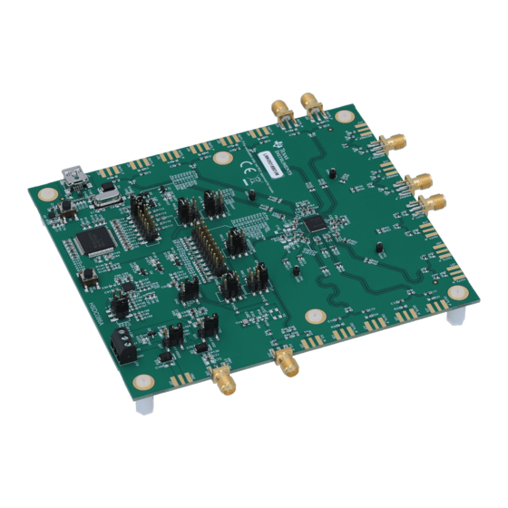
Overview
The LMK05318B EVM is an evaluation module for the LMK05318B Network Clock Generator and
Synchronizer. The EVM can be used for device evaluation, compliance testing, and system prototyping.
The EVM includes SMA connectors for clock inputs, oscillator inputs, and clock outputs to interface the
device with 50-Ω test equipment. The device can be configured through I2C or SPI using the onboard
microcontroller. The graphic interface TICS Pro can be used to program the LMK05318B registers and on-
chip EEPROM.
2
Trademarks
All trademarks are the property of their respective owners.
3
Features
•
LMK05318B DUT:
– DPLL with programmable loop bandwidth for input jitter and wander attenuation
– Two Analog PLLs (APLLs) for flexible low-jitter clock generation
– Two clock inputs supporting hitless switching and holdover
– Eight differential clock outputs, or combination of differential and up to eight LVCMOS clocks
– On-chip EEPROM for custom start-up clocks
•
SMA ports for clock input, oscillator inputs, and clock outputs
•
Onboard 48.0048-MHz XO and option to use external XO
•
USB MCU interface for I
•
Status LEDs for power supplies and device status indicators
4
What is Included
•
LMK05318BBEVM
•
Mini-USB cable
5
What is Needed
•
Windows PC with
•
Test Equipment
– DC power supply (5 V, 1 A)
– Real-time oscilloscope
– Source signal analyzer
– Precision frequency counter
– Signal generator and reference clock
SNAU253 – June 2020
Submit Documentation Feedback
2
C/SPI and GPIO pin control using TICS Pro GUI
TICS Pro Software GUI
Copyright © 2020, Texas Instruments Incorporated
SNAU253 – June 2020
LMK05318B EVM
LMK05318B EVM
1
Advertisement

Related Manuals for Texas Instruments LMK05318B EVM


Summary of Contents for Texas Instruments LMK05318B EVM
- Page 1 LMK05318B EVM Overview The LMK05318B EVM is an evaluation module for the LMK05318B Network Clock Generator and Synchronizer. The EVM can be used for device evaluation, compliance testing, and system prototyping. The EVM includes SMA connectors for clock inputs, oscillator inputs, and clock outputs to interface the device with 50-Ω...
- Page 2 Figure 3. Request, download and install Tics Pro: Texas Instruments Clocks and Synthesizers (TICS) Pro Software. In Tics Pro, go to the page EVM Quick Start page and follow the instructions. 4. To start a new design, go to the Wizard page in Tics Pro.
- Page 3 48.0048 MHz XO VIN1 = 5V VIN2 unused Figure 1. LMK05318B EVM with Default Jumper Settings Device Start-Up Modes The LMK05318B can start-up in one of three modes depending on the 3-level input level sampled on the HW_SW_CTRL pin upon power-on reset (POR). The start-up modes are listed in Table 2 SNAU253 –...
-
Page 4: Evm Configuration
To power up or power down the onboard XO, short pins 1-2 or pins 2-3 of J9. Logic Inputs and Outputs Table 1 to set voltage levels for GPIO pins. LMK05318B EVM User's Guide SNAU253 – June 2020 Submit Documentation Feedback Copyright © 2020, Texas Instruments Incorporated... - Page 5 DCO numerator by the programmable frequency deviation (FDEV) step size to adjust its (Logic outputs) frequency. FDEC STATE DPLL DCO NUMERATOR STATUS1/FDEC is No update always controlled by the 1 (Pulsed by MCU pin) Decremented SNAU253 – June 2020 LMK05318B EVM User's Guide Submit Documentation Feedback Copyright © 2020, Texas Instruments Incorporated...
- Page 6 After POR, the STATUS1 pin can be operated as an FDEC input in the same way described in Table In ROM + I C Mode, the two I C address LSBs are forced to 00b (address = 0x64h). LMK05318B EVM User's Guide SNAU253 – June 2020 Submit Documentation Feedback Copyright © 2020, Texas Instruments Incorporated...
- Page 7 EVM Schematics www.ti.com EVM Schematics Figure 2. Schematic 1 - Power Supply SNAU253 – June 2020 LMK05318B EVM User's Guide Submit Documentation Feedback Copyright © 2020, Texas Instruments Incorporated...
- Page 8 EVM Schematics www.ti.com Figure 3. Schematic 2 - Power Distribution LMK05318B EVM User's Guide SNAU253 – June 2020 Submit Documentation Feedback Copyright © 2020, Texas Instruments Incorporated...
- Page 9 EVM Schematics www.ti.com Figure 4. Schematic 3 - LMK05318B and XO Input Interfaces SNAU253 – June 2020 LMK05318B EVM User's Guide Submit Documentation Feedback Copyright © 2020, Texas Instruments Incorporated...
- Page 10 EVM Schematics www.ti.com Figure 5. Schematic 4- Clock Input Interfaces LMK05318B EVM User's Guide SNAU253 – June 2020 Submit Documentation Feedback Copyright © 2020, Texas Instruments Incorporated...
- Page 11 EVM Schematics www.ti.com Figure 6. Schematic 5 - Clock Output Interfaces (OUT0 to OUT3) SNAU253 – June 2020 LMK05318B EVM User's Guide Submit Documentation Feedback Copyright © 2020, Texas Instruments Incorporated...
- Page 12 EVM Schematics www.ti.com Figure 7. Schematic 6- Clock Outputs (OUT4 to OUT7) LMK05318B EVM User's Guide SNAU253 – June 2020 Submit Documentation Feedback Copyright © 2020, Texas Instruments Incorporated...
- Page 13 EVM Schematics www.ti.com Figure 8. Schematic 7 - Logic I/O Interfaces SNAU253 – June 2020 LMK05318B EVM User's Guide Submit Documentation Feedback Copyright © 2020, Texas Instruments Incorporated...
- Page 14 EVM Schematics www.ti.com Figure 9. Schematic 8 - USB MCU and I C/SPI Jumper Block LMK05318B EVM User's Guide SNAU253 – June 2020 Submit Documentation Feedback Copyright © 2020, Texas Instruments Incorporated...
- Page 15 EVM Schematics www.ti.com Figure 10. Schematic 9 - Hardware SNAU253 – June 2020 LMK05318B EVM User's Guide Submit Documentation Feedback Copyright © 2020, Texas Instruments Incorporated...
-
Page 16: Evm Layouts
EVM Layouts www.ti.com EVM Layouts Figure 11. Top Layer Composite View LMK05318B EVM User's Guide SNAU253 – June 2020 Submit Documentation Feedback Copyright © 2020, Texas Instruments Incorporated... - Page 17 EVM Layouts www.ti.com Figure 12. Layer 2 - Ground Plane SNAU253 – June 2020 LMK05318B EVM User's Guide Submit Documentation Feedback Copyright © 2020, Texas Instruments Incorporated...
- Page 18 EVM Layouts www.ti.com Figure 13. Layer 3 - Signal Routing LMK05318B EVM User's Guide SNAU253 – June 2020 Submit Documentation Feedback Copyright © 2020, Texas Instruments Incorporated...
- Page 19 EVM Layouts www.ti.com Figure 14. Layer 4 - Power Routing SNAU253 – June 2020 LMK05318B EVM User's Guide Submit Documentation Feedback Copyright © 2020, Texas Instruments Incorporated...
- Page 20 EVM Layouts www.ti.com Figure 15. Layer 5 - Ground Plane LMK05318B EVM User's Guide SNAU253 – June 2020 Submit Documentation Feedback Copyright © 2020, Texas Instruments Incorporated...
- Page 21 EVM Layouts www.ti.com Figure 16. Bottom Layer Composite View SNAU253 – June 2020 LMK05318B EVM User's Guide Submit Documentation Feedback Copyright © 2020, Texas Instruments Incorporated...
-
Page 22: Evm Bill Of Materials
ACTU 10%, X7R, 0603 C89, C94, C98, 0.01 µF CAP, CERM, 0402 GRM155R71H10 MuRata 0.01 µF, 50 V, ± 3KA88D 10%, X7R, 0402 LMK05318B EVM User's Guide SNAU253 – June 2020 Submit Documentation Feedback Copyright © 2020, Texas Instruments Incorporated... - Page 23 M30RC Connector Unshrouded Solutions Connector 0.100 in (2.54 mm) Surface Mount Terminal Block, 10.5x8.2x6.5 mm ED555/3DS On-Shore 3.5 mm Pitch, Technology 3x1, TH SNAU253 – June 2020 LMK05318B EVM User's Guide Submit Documentation Feedback Copyright © 2020, Texas Instruments Incorporated...
- Page 24 Vishay-Dale R86, R87, R89, 0.063 W, 0402 FKED R128, R148, R160 R106 33.2 RES, 33.2, 1%, 0402 CRCW040233R Vishay-Dale 0.063 W, 0402 2FKED LMK05318B EVM User's Guide SNAU253 – June 2020 Submit Documentation Feedback Copyright © 2020, Texas Instruments Incorporated...
- Page 25 Vishay-Dale 0.063 W, 0402 FKED R155 1.87 k RES, 1.87 k, 1%, 0402 CRCW04021K87 Vishay-Dale 0.063 W, AEC- FKED Q200 Grade 0, 0402 SNAU253 – June 2020 LMK05318B EVM User's Guide Submit Documentation Feedback Copyright © 2020, Texas Instruments Incorporated...
- Page 26 Crystal, 24 MHz, Crystal, ECS-240-20- ECS Inc. 20 pF, SMD 11.4x4.3x3.8 mm 5PXDN-TR Crystal, 48.0048 Crystal Oscillator 8W48070002 TXC Corporation MHz, 15 pF, LMK05318B EVM User's Guide SNAU253 – June 2020 Submit Documentation Feedback Copyright © 2020, Texas Instruments Incorporated...
- Page 27 0402 CRCW04020000 Vishay-Dale 0.063 W, AEC- Z0ED Q200 Grade 0, 0402 R105 33.2 RES, 33.2, 1%, 0402 CRCW040233R Vishay-Dale 0.063 W, 0402 2FKED SNAU253 – June 2020 LMK05318B EVM User's Guide Submit Documentation Feedback Copyright © 2020, Texas Instruments Incorporated...
- Page 28 CMOS Oscillator 10.000000 3.3 V 4-SMD, No Lead References • TICS Pro Software GUI • Texas Instruments Clocks and Synthesizers (TICS) Pro Software LMK05318B EVM User's Guide SNAU253 – June 2020 Submit Documentation Feedback Copyright © 2020, Texas Instruments Incorporated...
- Page 29 STANDARD TERMS FOR EVALUATION MODULES Delivery: TI delivers TI evaluation boards, kits, or modules, including any accompanying demonstration software, components, and/or documentation which may be provided together or separately (collectively, an “EVM” or “EVMs”) to the User (“User”) in accordance with the terms set forth herein.
- Page 30 www.ti.com Regulatory Notices: 3.1 United States 3.1.1 Notice applicable to EVMs not FCC-Approved: FCC NOTICE: This kit is designed to allow product developers to evaluate electronic components, circuitry, or software associated with the kit to determine whether to incorporate such items in a finished product and software developers to write software applications for use with the end product.
- Page 31 www.ti.com Concernant les EVMs avec antennes détachables Conformément à la réglementation d'Industrie Canada, le présent émetteur radio peut fonctionner avec une antenne d'un type et d'un gain maximal (ou inférieur) approuvé pour l'émetteur par Industrie Canada. Dans le but de réduire les risques de brouillage radioélectrique à...
- Page 32 www.ti.com EVM Use Restrictions and Warnings: 4.1 EVMS ARE NOT FOR USE IN FUNCTIONAL SAFETY AND/OR SAFETY CRITICAL EVALUATIONS, INCLUDING BUT NOT LIMITED TO EVALUATIONS OF LIFE SUPPORT APPLICATIONS. 4.2 User must read and apply the user guide and other available documentation provided by TI regarding the EVM prior to handling or using the EVM, including without limitation any warning or restriction notices.
- Page 33 Notwithstanding the foregoing, any judgment may be enforced in any United States or foreign court, and TI may seek injunctive relief in any United States or foreign court. Mailing Address: Texas Instruments, Post Office Box 655303, Dallas, Texas 75265 Copyright © 2019, Texas Instruments Incorporated...
- Page 34 TI products. TI’s provision of these resources does not expand or otherwise alter TI’s applicable warranties or warranty disclaimers for TI products.IMPORTANT NOTICE Mailing Address: Texas Instruments, Post Office Box 655303, Dallas, Texas 75265 Copyright © 2021, Texas Instruments Incorporated...
Need help?
Do you have a question about the LMK05318B EVM and is the answer not in the manual?
Questions and answers