Table of Contents
Advertisement
Quick Links
Advertisement
Table of Contents

Subscribe to Our Youtube Channel
Related Manuals for Texas Instruments LMK03328EVM


Summary of Contents for Texas Instruments LMK03328EVM
- Page 1 LMK03328EVM User's Guide Literature Number: SNAU184 August 2015...
-
Page 2: Table Of Contents
Example Performance Measurements ........Using TI’s USB2ANY Module for In-System Programming of LMK03328 ..................11.1 USB2ANY Board Connections ..................11.2 Ordering a USB2ANY Module Table of Contents SNAU184 – August 2015 Submit Documentation Feedback Copyright © 2015, Texas Instruments Incorporated... - Page 3 Soft Pin Mode, EEPROM Page 5, OUT7 – 125 MHz LVPECL (Spurs On) ......................USB2ANY Module ................... USB2ANY Board Connections ................... 10-pin Cable Connection to J4 ......................10-pin Cable Pinout ................USB2ANY Board Connector Pinout Diagram SNAU184 – August 2015 List of Figures Submit Documentation Feedback Copyright © 2015, Texas Instruments Incorporated...
- Page 4 Soft Pin Mode - EEPROM Page Configurations (EVM-Default EEPROM Image) ........... Output RMS Jitter Summary – Soft Pin Mode, EEPROM Page 5 ............USB2ANY Board Connector J4 and 10-pin Cable Pinouts List of Tables SNAU184 – August 2015 Submit Documentation Feedback Copyright © 2015, Texas Instruments Incorporated...
-
Page 5: Lmk03328Evm Photo
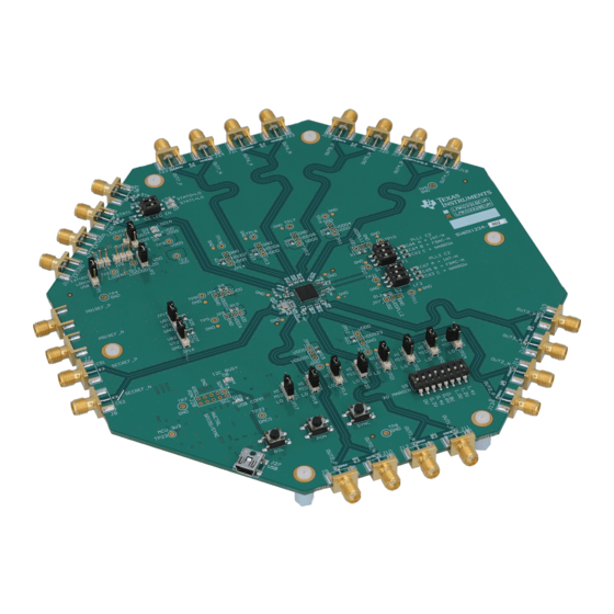
User's Guide SNAU184 – August 2015 LMK03328EVM User’s Guide Figure 1. LMK03328EVM Photo SNAU184 – August 2015 LMK03328EVM User’s Guide Submit Documentation Feedback Copyright © 2015, Texas Instruments Incorporated... -
Page 6: Overview
Texas Instruments LMK03328 Ultra-Low-Jitter Clock Generator with Dual PLLs, 8 outputs, 2 inputs, and integrated EEPROM. The LMK03328EVM can be used as a flexible, multi-output clock source for compliance testing, performance evaluation, and initial system prototyping. The onboard edge-launch SMA ports provide access to the LMK03328 clock inputs and outputs for interfacing to test equipment and reference boards using commercially available coaxial cables, adapters, or baluns (not included). -
Page 7: Modes Of Operation
This section describes the jumpers and connectors on the EVM, as well as how to connect, set-up, and use the LMK03328EVM. When operating the LMK03328EVM, the power supply, clock inputs, and clock outputs can be connected to the SMA ports shown in Figure 2. -
Page 8: Power, Input, And Output Connections
Configuring the EVM www.ti.com Figure 2. Power, Input, and Output Connections LMK03328EVM User’s Guide SNAU184 – August 2015 Submit Documentation Feedback Copyright © 2015, Texas Instruments Incorporated... -
Page 9: Configuring The Power Supply
NOTE: Some power connections will NOT be used or required to operate the EVM. Figure 3. Power Terminals and Jumpers SNAU184 – August 2015 LMK03328EVM User’s Guide Submit Documentation Feedback Copyright © 2015, Texas Instruments Incorporated... -
Page 10: Power Configurations
Selects VDDO = 2.5 V In typical configurations, the LMK03328EVM can consume more current than USB 2.0 limit of 0.5 A. Thus, it is advised to not use the USB5V rail to power the on-board LDO regulators (i.e. do not tie pins 1-2 on JP1), unless the LMK03328 device configuration and peripheral circuitry are assured to never exceed 0.5 A current limit set by the TPS2553 USB switch (U10). -
Page 11: Configuring The Control Pins
• For Hard Pin Modes, refer to Table 4. Jumpers not listed in Table 4 have identical functions described Table SNAU184 – August 2015 LMK03328EVM User’s Guide Submit Documentation Feedback Copyright © 2015, Texas Instruments Incorporated... -
Page 12: Control Pin Interfaces For Soft Pin Mode Or Register Default Mode (Jp18 Hwctrl = Lo)
7-BIT SLAVE ADDRESS GPIO1 GPIO1 STATE JP20 (excludes W/R bit) (3-level input) 1010100b / 0x54 (JP Default) 1010101b / 0x55 1010111b / 0x57 LMK03328EVM User’s Guide SNAU184 – August 2015 Submit Documentation Feedback Copyright © 2015, Texas Instruments Incorporated... - Page 13 By default, JP24 is left open, so switch S5 can be used to set the frequency margining offset. See the description for S5 (XO MARGIN). SYNC push-button switch SYNC When pressed, the GPIO0 pin is pulled down to assert SYNC. SNAU184 – August 2015 LMK03328EVM User’s Guide Submit Documentation Feedback Copyright © 2015, Texas Instruments Incorporated...
- Page 14 Pin 4: N/C Pin 3: N/C (not populated) Pin 5: GND Pin 6: N/C Pin 7: REFSEL Pin 8: HW_SW_CTRL Pin 9: PDN Pin 10: GPIO0 LMK03328EVM User’s Guide SNAU184 – August 2015 Submit Documentation Feedback Copyright © 2015, Texas Instruments Incorporated...
-
Page 15: Configuring The Pll Loop Filters
Only one position should be ON at a time (all others are OFF). PLL2 Loop Filter C2 Capacitor Select S2 has the same capacitor selection table as above for S1. SNAU184 – August 2015 LMK03328EVM User’s Guide Submit Documentation Feedback Copyright © 2015, Texas Instruments Incorporated... -
Page 16: Configuring The Reference Inputs
R29 and R33 with the shunt resistor connected to GND by tying pins 2-3 of JP16. 125 3.3-V LVCMOS SECREF_P Driver LMK03328 Ro = 50 375 Figure 5. Interfacing a 3.3-V LVCMOS Clock Input to SECREF_P LMK03328EVM User’s Guide SNAU184 – August 2015 Submit Documentation Feedback Copyright © 2015, Texas Instruments Incorporated... -
Page 17: Configuring The Clock Outputs
The on-board MSP430F5529 USB microcontroller (U8) provides an I2C host interface to the LMK03328 slave device. The device registers can be controlled via USB using the GUI platform running on a Host SNAU184 – August 2015 LMK03328EVM User’s Guide Submit Documentation Feedback Copyright © 2015, Texas Instruments Incorporated... -
Page 18: Evm Quick Start Guide
7. Refer to the Soft Pin Mode Control Interfaces descriptions in Table 3 for configuration of PLL reference input selection (JP17), output SYNC (switch S4), and XTAL frequency margining (JP23, JP24, and switch S5). LMK03328EVM User’s Guide SNAU184 – August 2015 Submit Documentation Feedback Copyright © 2015, Texas Instruments Incorporated... -
Page 19: Soft Pin Mode - Eeprom Page Configurations (Evm-Default Eeprom Image)
PRIREF loss of 25 MHz LVCMOS PLL2 loss of lock STATUS1 (active low) (active low) (active low) signal (active low) 3.3V (active low) (active low) SNAU184 – August 2015 LMK03328EVM User’s Guide Submit Documentation Feedback Copyright © 2015, Texas Instruments Incorporated... -
Page 20: Evm Layout
EVM Layout www.ti.com EVM Layout Figure 6. Top Overlay LMK03328EVM User’s Guide SNAU184 – August 2015 Submit Documentation Feedback Copyright © 2015, Texas Instruments Incorporated... -
Page 21: Top Solder Mask
EVM Layout www.ti.com Figure 7. Top Solder Mask SNAU184 – August 2015 LMK03328EVM User’s Guide Submit Documentation Feedback Copyright © 2015, Texas Instruments Incorporated... - Page 22 EVM Layout www.ti.com Figure 8. Layer 1 (Top Side) LMK03328EVM User’s Guide SNAU184 – August 2015 Submit Documentation Feedback Copyright © 2015, Texas Instruments Incorporated...
- Page 23 EVM Layout www.ti.com Figure 9. Layer 2 SNAU184 – August 2015 LMK03328EVM User’s Guide Submit Documentation Feedback Copyright © 2015, Texas Instruments Incorporated...
- Page 24 EVM Layout www.ti.com Figure 10. Layer 3 LMK03328EVM User’s Guide SNAU184 – August 2015 Submit Documentation Feedback Copyright © 2015, Texas Instruments Incorporated...
- Page 25 EVM Layout www.ti.com Figure 11. Layer 4 SNAU184 – August 2015 LMK03328EVM User’s Guide Submit Documentation Feedback Copyright © 2015, Texas Instruments Incorporated...
- Page 26 EVM Layout www.ti.com Figure 12. Layer 5 LMK03328EVM User’s Guide SNAU184 – August 2015 Submit Documentation Feedback Copyright © 2015, Texas Instruments Incorporated...
- Page 27 EVM Layout www.ti.com Figure 13. Layer 6 SNAU184 – August 2015 LMK03328EVM User’s Guide Submit Documentation Feedback Copyright © 2015, Texas Instruments Incorporated...
- Page 28 EVM Layout www.ti.com Figure 14. Layer 7 LMK03328EVM User’s Guide SNAU184 – August 2015 Submit Documentation Feedback Copyright © 2015, Texas Instruments Incorporated...
- Page 29 EVM Layout www.ti.com Figure 15. Layer 8 (Bottom Side, View from Top) SNAU184 – August 2015 LMK03328EVM User’s Guide Submit Documentation Feedback Copyright © 2015, Texas Instruments Incorporated...
-
Page 30: Bottom Solder Mask
EVM Layout www.ti.com Figure 16. Bottom Solder Mask LMK03328EVM User’s Guide SNAU184 – August 2015 Submit Documentation Feedback Copyright © 2015, Texas Instruments Incorporated... -
Page 31: Bottom Overlay
EVM Layout www.ti.com Figure 17. Bottom Overlay SNAU184 – August 2015 LMK03328EVM User’s Guide Submit Documentation Feedback Copyright © 2015, Texas Instruments Incorporated... -
Page 32: Drill Drawing
EVM Layout www.ti.com Figure 18. Drill Drawing LMK03328EVM User’s Guide SNAU184 – August 2015 Submit Documentation Feedback Copyright © 2015, Texas Instruments Incorporated... -
Page 33: Evm Schematic
1902C LBL1 PCB Label LOGO Size: 0.65" x 0.20 " Texas I nstruments LOGO LOGO Pb-Free Symbol FCC disclaimer PCB Number: SV601123 PCB Rev: SNAU184 – August 2015 LMK03328EVM User’s Guide Submit Documentation Feedback Copyright © 2015, Texas Instruments Incorporated... - Page 34 2 = 1.8V (open) LDO_SEL_2V5 Vout=2.5V (short pins 2-3): Ra=4.99k, Rb=3.92k // 5.76k=2.33k 3 = 2.5V Vout=3.3V: (short pins 1-2) Ra=4.99k, Rb=3.92k // 2.67k=1.59k LDOSEL LMK03328EVM User’s Guide SNAU184 – August 2015 Submit Documentation Feedback Copyright © 2015, Texas Instruments Incorporated...
- Page 35 - XA/SECREF_P and XB/SECREF_N traces should be separated and kept away from other traces. - Avoid routing below the XTAL pads and use plane cutouts below XTAL pads to minimize parasitic capacitance. SNAU184 – August 2015 LMK03328EVM User’s Guide Submit Documentation Feedback Copyright © 2015, Texas Instruments Incorporated...
- Page 36 - Use sufficient clearance between OUT# paths, as well as from other dynamic signal paths. - Avoid crossing Digital signal/return paths with clock OUT signal/return paths; if unavoidable, cross at a 90 deg. angle LMK03328EVM User’s Guide SNAU184 – August 2015 Submit Documentation Feedback Copyright © 2015, Texas Instruments Incorporated...
- Page 37 0.8V = 18.7k pulldown only 1.0V = 34.8k pulldown only 1.2V = 84.5k pulldown only U2A_SDA R109 1.4V = OPEN U2A_SCL R110 10pF 10pF SNAU184 – August 2015 LMK03328EVM User’s Guide Submit Documentation Feedback Copyright © 2015, Texas Instruments Incorporated...
- Page 38 - SPI interface (I2C/SMBus only) USER NOTE: 0R resistors between MSP430 and "U2A_GPIO[4:7]" nets should be de-populated before attaching the External USB2ANY module to the USB2ANY Header. LMK03328EVM User’s Guide SNAU184 – August 2015 Submit Documentation Feedback Copyright © 2015, Texas Instruments Incorporated...
-
Page 39: Evm Bill Of Materials
3.5A Ferrite Bead, 60 ohm @ 100MHz, MPZ1608S600A FID1, FID2, FID3, FID4, Fiducial mark. There is nothing to buy or FID5, FID6, FID7, FID8 mount. SNAU184 – August 2015 LMK03328EVM User’s Guide Submit Documentation Feedback Copyright © 2015, Texas Instruments Incorporated... - Page 40 RES, 100, 1%, 0.063 W, 0402 Vishay-Dale CRCW0402100RFKED R73, R74, R75 R7, R8, R139, R151, R157 RES, 33k ohm, 5%, 0.1W, 0603 Vishay-Dale CRCW060333K0JNEA LMK03328EVM User’s Guide SNAU184 – August 2015 Submit Documentation Feedback Copyright © 2015, Texas Instruments Incorporated...
- Page 41 C84, C85 CAP, CERM, 8.2 pF, 25 V, +/- 5%, MuRata GRM1555C1E8R2CA01D C0G/NP0, 0402 C90, C91 CAP, CERM, 10pF, 50V, +/-5%, C0G/NP0, Kemet C0603C100J5GACTU 0603 SNAU184 – August 2015 LMK03328EVM User’s Guide Submit Documentation Feedback Copyright © 2015, Texas Instruments Incorporated...
-
Page 42: Recommended Test Instruments
Reference Oscillator: Low-jitter clock source with LVCMOS or Differential output to SMA connector(s) to interface to PRIREF or SECREF inputs • Balun: M/A-COM H-183-4 (30-3000 MHz) 180° coupler, or equivalent LMK03328EVM User’s Guide SNAU184 – August 2015 Submit Documentation Feedback Copyright © 2015, Texas Instruments Incorporated... -
Page 43: Example Performance Measurements
100 MHz LVPECL OUT7 100 MHz LVPECL Figure 22 Figure 19. Soft Pin Mode, EEPROM Page 5, OUT0 – 156.25 MHz LVPECL (Spurs On) SNAU184 – August 2015 LMK03328EVM User’s Guide Submit Documentation Feedback Copyright © 2015, Texas Instruments Incorporated... -
Page 44: Soft Pin Mode, Eeprom Page 5, Out3 - 125 Mhz Lvpecl (Spurs On)
Example Performance Measurements www.ti.com Figure 20. Soft Pin Mode, EEPROM Page 5, OUT3 – 125 MHz LVPECL (Spurs On) LMK03328EVM User’s Guide SNAU184 – August 2015 Submit Documentation Feedback Copyright © 2015, Texas Instruments Incorporated... -
Page 45: Soft Pin Mode, Eeprom Page 5, Out5 - 133.33 Mhz Lvpecl (Spurs On)
Example Performance Measurements www.ti.com Figure 21. Soft Pin Mode, EEPROM Page 5, OUT5 – 133.33 MHz LVPECL (Spurs On) SNAU184 – August 2015 LMK03328EVM User’s Guide Submit Documentation Feedback Copyright © 2015, Texas Instruments Incorporated... -
Page 46: Soft Pin Mode, Eeprom Page 5, Out7 - 125 Mhz Lvpecl (Spurs On)
Example Performance Measurements www.ti.com Figure 22. Soft Pin Mode, EEPROM Page 5, OUT7 – 125 MHz LVPECL (Spurs On) LMK03328EVM User’s Guide SNAU184 – August 2015 Submit Documentation Feedback Copyright © 2015, Texas Instruments Incorporated... -
Page 47: Using Ti's Usb2Any Module For In-System Programming Of Lmk03328
Figure 23. USB2ANY Module Because the USB2ANY module implements the same MSP430-based USB-to-I2C interface/firmware as the one integrated on the LMK03328EVM, the same EVM GUI platform can be used to easily program the device in-system. Once the customer’s system software/firmware is enabled and can provide reliable configuration of the LMK03328, then the provisional I2C header may be removed or superseded in the next iteration of the hardware design. -
Page 48: Usb2Any Board Connections
The opposite end of the cable should be connected to the target board. The red stripe on the cable indicates pin 1 as shown in Figure LMK03328EVM User’s Guide SNAU184 – August 2015 Submit Documentation Feedback Copyright © 2015, Texas Instruments Incorporated... - Page 49 Using TI’s USB2ANY Module for In-System Programming of LMK03328 www.ti.com Figure 25. 10-pin Cable Connection to J4 Figure 26. 10-pin Cable Pinout SNAU184 – August 2015 LMK03328EVM User’s Guide Submit Documentation Feedback Copyright © 2015, Texas Instruments Incorporated...
-
Page 50: Usb2Any Board Connector Pinout Diagram
3-pin “I2C header” on the application board and 3 jumper wires to connect the SDA, SCL, and GND signals from J4 of USB2ANY to the I2C header. LMK03328EVM User’s Guide SNAU184 – August 2015 Submit Documentation Feedback Copyright © 2015, Texas Instruments Incorporated... -
Page 51: 11.2 Ordering A Usb2Any Module
1. Request/Reason: 1 pc. USB2ANY module for LMK03328 in-system programming/prototyping 2. Company Name: 3. Application/End-Equipment: 4. LMK03328 Est. Annual Volume/Year: 5. Ship-To Address: SNAU184 – August 2015 LMK03328EVM User’s Guide Submit Documentation Feedback Copyright © 2015, Texas Instruments Incorporated... - Page 52 STANDARD TERMS AND CONDITIONS FOR EVALUATION MODULES Delivery: TI delivers TI evaluation boards, kits, or modules, including any accompanying demonstration software, components, or documentation (collectively, an “EVM” or “EVMs”) to the User (“User”) in accordance with the terms and conditions set forth herein. Acceptance of the EVM is expressly subject to the following terms and conditions.
- Page 53 FCC Interference Statement for Class B EVM devices NOTE: This equipment has been tested and found to comply with the limits for a Class B digital device, pursuant to part 15 of the FCC Rules. These limits are designed to provide reasonable protection against harmful interference in a residential installation.
- Page 54 【無線電波を送信する製品の開発キットをお使いになる際の注意事項】 開発キットの中には技術基準適合証明を受けて いないものがあります。 技術適合証明を受けていないもののご使用に際しては、電波法遵守のため、以下のいずれかの 措置を取っていただく必要がありますのでご注意ください。 1. 電波法施行規則第6条第1項第1号に基づく平成18年3月28日総務省告示第173号で定められた電波暗室等の試験設備でご使用 いただく。 2. 実験局の免許を取得後ご使用いただく。 3. 技術基準適合証明を取得後ご使用いただく。 なお、本製品は、上記の「ご使用にあたっての注意」を譲渡先、移転先に通知しない限り、譲渡、移転できないものとします。 上記を遵守頂けない場合は、電波法の罰則が適用される可能性があることをご留意ください。 日本テキサス・イ ンスツルメンツ株式会社 東京都新宿区西新宿6丁目24番1号 西新宿三井ビル 3.3.3 Notice for EVMs for Power Line Communication: Please see http://www.tij.co.jp/lsds/ti_ja/general/eStore/notice_02.page 電力線搬送波通信についての開発キットをお使いになる際の注意事項については、次のところをご覧くださ い。http://www.tij.co.jp/lsds/ti_ja/general/eStore/notice_02.page SPACER EVM Use Restrictions and Warnings: 4.1 EVMS ARE NOT FOR USE IN FUNCTIONAL SAFETY AND/OR SAFETY CRITICAL EVALUATIONS, INCLUDING BUT NOT LIMITED TO EVALUATIONS OF LIFE SUPPORT APPLICATIONS.
- Page 55 Notwithstanding the foregoing, any judgment may be enforced in any United States or foreign court, and TI may seek injunctive relief in any United States or foreign court. Mailing Address: Texas Instruments, Post Office Box 655303, Dallas, Texas 75265 Copyright © 2015, Texas Instruments Incorporated...
- Page 56 IMPORTANT NOTICE Texas Instruments Incorporated and its subsidiaries (TI) reserve the right to make corrections, enhancements, improvements and other changes to its semiconductor products and services per JESD46, latest issue, and to discontinue any product or service per JESD48, latest issue.
- Page 57 Mouser Electronics Authorized Distributor Click to View Pricing, Inventory, Delivery & Lifecycle Information: Texas Instruments LMK03328EVM...
Need help?
Do you have a question about the LMK03328EVM and is the answer not in the manual?
Questions and answers