Table of Contents
Advertisement
Quick Links
FES93XX
User Manual
All rights reserved. Product description and product specifications are subject to change without notice.
For latest product information, please visit Acnodes' website at www.acnodes.com
14628 Central Ave. Chino, CA 91710
© Copyright 2020 Acnodes Corp.
Compact DIN-Rail Fanless Embedded Box PC
Intel Pentium N4200 Quad-Core Processor
-25°C to 70°C Wide Range Working Temperature
1
Tel: 909.597.7588
Fax: 909.597.1939
Advertisement
Table of Contents

Related Manuals for Acnodes FES93 Series


Summary of Contents for Acnodes FES93 Series
- Page 1 -25°C to 70°C Wide Range Working Temperature User Manual All rights reserved. Product description and product specifications are subject to change without notice. For latest product information, please visit Acnodes’ website at www.acnodes.com 14628 Central Ave. Chino, CA 91710 Tel: 909.597.7588 Fax: 909.597.1939...
-
Page 2: Table Of Contents
Table of Contents Legal Information ........................Declaration of Conformity ......................Safety Precautions ........................Service and Maintenance ......................Introduction Specifications of FES9300 ..................... Specifications of FES9310 .................... Specifications of FES9320 .................... Specifications of FES9330 .................... Dimension ........................Front View ......................1.5.1 1.5.2 Top View ......................... - Page 3 Installing the System Enclosure .................. DIN Rail Installation ....................... Wall Mount Bracket Installation (with WM-300V) ............Wall Mount Bracket Installation (with WM-300H) ............Powering on the System ....................3.7.1 Powering On Using the Power Button ..............Powering On Using An External Non-Latched Switch ..........3.7.2 Powering On Using An External Latched Switch............
-
Page 4: Legal Information
Legal Information All of Acnodes' products shall be subject to the latest Standard Warranty Policy. Acnodes may modify, update or upgrade the software, firmware or any accompanying user documentation without any prior notice. Before installing any software, applications or components provided by a third party, customer should ensure that they are compatible and interoperable with Acnodes' product by checking in advance with Acnodes. -
Page 5: Declaration Of Conformity
Declaration of Conformity This equipment has been tested and found to comply with the limits for a Class A digital device, pursuant to part 15 of the FCC Rules. These limits are designed to provide reasonable protection against harmful interference when the equipment is operated in a commercial environment. -
Page 6: Safety Precautions
Safety Precautions Read these instructions carefully before you install, operate, or transport the system. Install the system or DIN rail associated with, at a sturdy location Install the power socket outlet near the system where it is easily accessible ... -
Page 7: Service And Maintenance
Service and Maintenance ONLY qualified personnel should service the system Shutdown the system, disconnect the power cord and all other connections before servicing the system When replacing/ installing additional components (expansion card, memory module, etc.), insert them as gently as possible while assuring proper connector engagement ESD Precautions Handle add-on module, motherboard by their retention screws or the module’s frame/ heat ... -
Page 8: Introduction
Introduction The FES93XX series are ultra-compact fanless embedded computers featuring Intel® Apollo-Lake Atom™ x7-E3950 or Pentium® N4200 processor. It has a compact and rugged chassis with dimensions measuring just 56 (W) x 153 (H) x 108 (D) mm. Designed for DIN rail mounting with front panel I/O port access, the FES93XX is easy to setup and ideal for industrial applications where space is limited. -
Page 9: Specifications Of Fes9300
FES9300 Specification System Core Processor Intel® Atom™ E3950 1.6/ 2.0GHz quad-core processor Graphics Integrated Intel® HD Graphics 505 Memory 1x SODIMM socket for DDR3L-1866, up to 8GB Panel I/O Interface Ethernet 3x Gigabit Ethernet ports by Intel® I210 GbE controller IEEE 802.3at PoE+ on port #1 and #2 1x DVI-I connector for both analog RGB and DVI outputs, supporting up Video Port... - Page 10 Humidity 10%~90% , non-condensing Operating, 5 Grms, 5-500 Hz, 3 Axes (w/ SSD, according to Vibration IEC60068-2-64) Operating, 50 Grms, Half-sine 11 ms Duration (w/ SSD, according to Shock IEC60068-2-27) CE/FCC Class A, according to EN 55022 & EN 55024 ** For sub-zero operating temperature, a wide temperature HDD drive or Solid State Disk (SSD) is required.
-
Page 11: Specifications Of Fes9310
FES9310 Specification System Core Processor Intel® Atom™ E3950 1.6/ 2.0GHz quad-core processor Graphics Integrated Intel® HD Graphics 505 Memory 1x SODIMM socket for DDR3L-1866, up to 8GB Panel I/O Interface Ethernet 3x Gigabit Ethernet ports by Intel® I210 GbE controller 1x DVI-I connector for both analog RGB and DVI outputs, supporting up Video Port to 1920 x 1200 resolution... - Page 12 Operating, 5 Grms, 5-500 Hz, 3 Axes (w/ SSD, according to Vibration IEC60068-2-64) Operating, 50 Grms, Half-sine 11 ms Duration (w/ SSD, according to Shock IEC60068-2-27) CE/FCC Class A, according to EN 55022 & EN 55024 ** For sub-zero operating temperature, a wide temperature HDD drive or Solid State Disk (SSD) is required.
-
Page 13: Specifications Of Fes9320
FES9320 Specification System Core Processor Intel® Pentium® N4200 1.1/ 2.5GHz quad-core processor Graphics Integrated Intel® HD Graphics 505 Memory 1x SODIMM socket for DDR3L-1866, up to 8GB Panel I/O Interface Ethernet 3x Gigabit Ethernet ports by Intel® I210 GbE controller IEEE 802.3at PoE+ on port #1 and #2 1x DVI-I connector for both analog RGB and DVI outputs, supporting up Video Port... - Page 14 Humidity 10%~90% , non-condensing Operating, 5 Grms, 5-500 Hz, 3 Axes (w/ SSD, according to Vibration IEC60068-2-64) Operating, 50 Grms, Half-sine 11 ms Duration (w/ SSD, according to Shock IEC60068-2-27) CE/FCC Class A, according to EN 55022 & EN 55024 ** For sub-zero operating temperature, a wide temperature HDD drive or Solid State Disk (SSD) is required.
-
Page 15: Specifications Of Fes9330
FES9330 Specification System Core Processor Intel® Pentium® N4200 1.1/ 2.5GHz quad-core processor Graphics Integrated Intel® HD Graphics 505 Memory 1x SODIMM socket for DDR3L-1866, up to 8GB Panel I/O Interface Ethernet 3x Gigabit Ethernet ports by Intel® I210 GbE controller 1x DVI-I connector for both analog RGB and DVI outputs, supporting up Video Port to 1920 x 1200 resolution... - Page 16 Operating, 5 Grms, 5-500 Hz, 3 Axes (w/ SSD, according to Vibration IEC60068-2-64) Operating, 50 Grms, Half-sine 11 ms Duration (w/ SSD, according to Shock IEC60068-2-27) CE/FCC Class A, according to EN 55022 & EN 55024 ** For sub-zero operating temperature, a wide temperature HDD drive or Solid State Disk (SSD) is required.
-
Page 17: Dimension
Dimension 1.5.1 Front View... -
Page 18: Top View
1.5.2 Top View... -
Page 19: Bottom View
1.5.3 Bottom View... -
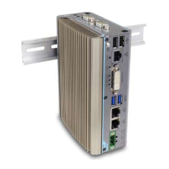
Page 20: Mounting Options
Mounting Options The system comes with various mounting options such as DIN-rail and wall-mount bracket. DIN-rail mount clip is shipped with FES93XX series as standard mounting option. Two optional mounting brackets, WM-300V and WM-300H, are available for wall-mount applications. 1.6.1 DIN-Rail Mount Clip... -
Page 21: Wall Mount Bracket (Wm-300V)
1.6.2 Wall Mount Bracket (WM-300V) -
Page 22: Wall Mount Bracket (Wm-300H)
1.6.3 Wall Mount Bracket (WM-300H) -
Page 23: System Overview
System Overview Upon receiving and unpacking FES93XX, please check immediately if the package contains all the items listed in the following table. If any item(s) are missing or damaged, please contact Acnodes. Unpacking the System Item Description FES9300 / 9310 / 9320 / 9330 ultra-compact fanless controller (Please verify additionally purchased accessories such as DDR3L module or mSATA SSD, etc.) -
Page 24: Front Panel
Front Panel The front panel of FES93XX feature rich I/O ports. It has three Gigabit Ethernet ports (two are 802.3at Gigabit PoE+ ports for FES9300 and FES9320), two USB3.0 ports, two USB2.0 ports, one DVI-I connector for VGA + DVI dual video output and 3-pin terminal block for DC input. -
Page 25: Usb 2.0 Port
2.2.1 USB 2.0 Port The USB2.0 ports are implemented via native xHCI (eXtensible Host Controller Interface) controller in Atom E3950/ Pentium N4200 SoC and are backward compatible with USB 1.1 and USB 1.0 devices. Legacy USB support is also provided so you can use USB keyboard/ mouse in DOS environment. -
Page 26: Power Button
2.2.2 Power Button The power button is a non-latched switch for ATX mode on/off operation. To turn on the system, press the power button and the PWR LED should light-up green. To turn off the system, issuing a shutdown command in OS is preferred, or you can simply press the power button. -
Page 27: Reset Button
2.2.3 Reset Button The reset button is used to manually reset the system in case of system halt or malfunction. To avoid unexpected reset, the button is purposely placed behind the panel. To reset, please use a pin-like object (eg. tip of a pen) to access the reset button. -
Page 28: Gigabit Ethernet
2.2.4 Gigabit Ethernet The system offers three Gigabit Ethernet ports using Intel® I210 GbE controller. From top to bottom, they are port #3, #1 and #2. When plugged in and connected via the Ethernet cable, the LEDs on the RJ45 connector indicate connection status and speed. -
Page 29: System Status Led
2.2.5 System Status LED There are three LED indicators on the front panel: PWR, HDD, and WDT. The descriptions of these three LEDs are listed in the following table. Indicator Color Description Green Power indicator, lid when system is on Hard drive indicator, flashing when SATA HDD is active Watchdog timer indicator, flashing when watchdog timer has Yellow... -
Page 30: Dvi-I Port
VGA signals. The DVI and VGA outputs are directly driven by integrated Intel HD graphics engine and support up to 1920 x 1200 resolution. For VGA monitor, Acnodes offers a specialized DVI-to-VGA adapter as an accessory shipped with the system. This adapter supports VGA DDC signals and thus eliminates compatibility issues with VGA monitors. -
Page 31: Usb 3.0 Port
2.2.7 USB 3.0 Port The system offers two USB 3.0 (SuperSpeed USB) ports on its front panel. They are implemented by native xHCI (eXtensible Host Controller Interface) controller in Atom E3950/ Pentium N4200 SoC and are backward compatible with USB 2.0, USB 1.1 and USB 1.0 devices. -
Page 32: Ieee 802.3At Power Over Ethernet Port #1 & #2 (Fes9300/ Fes9320 Only)
2.2.8 IEEE 802.3at Power over Ethernet Port #1 & #2 (FES9300/ 9320 Only) The Power over Ethernet (PoE) port supply power and data on a standard CAT-5/CAT-6 Ethernet cable. Acting as a PSE (Power Sourcing Equipment), compliant with IEEE 802.3at, each port delivers up to 25W to a Powered Device (PD). PoE automatically detects and determine if the connected device is PoE PD or not before supplying power, making it compatible with standard Ethernet devices as well. -
Page 33: 3-Pin Terminal Block For Dc Input
2.2.9 3-Pin Terminal Block for DC Input The system accepts a wide range of DC power input from 8 to 35V via a 3-pin pluggable terminal block, which is fit for field usage where DC power is usually provided. The screw clamping mechanism on the terminal block offers connection reliability when wiring DC power. -
Page 34: Top Panel
Top Panel The top panel of features additional I/O functions, such as 3.5mm speaker-out/ microphone-in jacks and COM ports implemented using ITE8786 SIO chip. Item Description COM port 1 Software programmable RS-232/ 422/ 485 port Can be configured as: COM port 2/ 3/ 4 COM2: single RS-422/ 485 port COM2/ COM3/ COM4: three 3-wire RS-232 ports Microphone-in... -
Page 35: Com Port (Com1)
2.3.1 COM Port (COM1) Implemented using industrial-grade ITE8786 Super IO chip (-40 to 85°C) and provide up to 921600 bps baud rate, COM1 is a software-configurable RS-232/422/485 port via 9-pin D-Sub male connector. The operation mode, slew rate and termination of COM1 can be set in BIOS setup utility. -
Page 36: Com Ports (Com2/ Com3/ Com4)
2.3.2 COM Ports (COM2/ COM3/ COM4) Implemented using industrial-grade ITE8786 Super IO chip (-40 to 85°C) and provide up to 921600 bps baud rate, the second D-Sub male connector (COM2/ 3/ 4) can be configured in BIOS as single RS-422/ 485 port (COM2) or three 3-wire RS-232 ports (COM2/COM3/COM4). -
Page 37: Mm Microphone-In/ Speaker-Out Jack
2.3.3 3.5mm Microphone-in/ Speaker-out Jack ® The system provides audio function using Intel High Definition Audio in Atom E3950/ Pentium N4200 SoC and Realtek ALC262 codec. There are two audio jacks on the top panel. The port is used for microphone input, and port is used for speaker output. -
Page 38: Internal I/O
Internal I/O The system’s internal I/O connectors consist of a SO-DIMM socket, mini-PCIe slot with USIM slot, a half-size mSATA port, and a I/O port for application-oriented expansion purposes. 2.4.1 DDR3L SO-DIMM Socket The system has an internal SO-DIMM slot supporting DDR3L-1866 memory module up to 8GB in capacity. -
Page 39: Full-Size Mini-Pcie Socket
2.4.2 Full-size mini-PCIe Socket The system provides a full-size mini-PCIe socket that is in compliance with mini-PCIe specification rev. 1.2. The mini-PCIe socket is designed with SIM card support. With a SIM card installed, your system can access the internet via your network provider’s 3G/ 4G network. - Page 40 mini-PCIe Pin Definition Pin # Signal Pin # Signal WAKE# +3.3Vaux COEX1 COEX2 +1.5V CLKREQ# UIM_PWR UIM_DATA REFCLK- UIM_CLK REFCLK+ UIM_RESET UIM_VPP Mechanical Key Reserved* (UIM_C8) Reserved* (UIM_C4) W_DISABLE# PERST# PERn0 +3.3Vaux PERp0 +1.5V SMB_CLK PETn0 SMB_DATA PETp0 USB_D- USB_D+ +3.3Vaux +3.3Vaux LED_WWAN#...
-
Page 41: Half-Size Msata Socket
2.4.3 Half-size mSATA Socket The system features one half-size mSATA socket. You can install a half-size mSATA SSD for operating system installation. The half-size mSATA SSD has all the advantages of solid state disk technology such as lower power consumption and is higher shock/ vibration resistant over traditional hard disk drives. - Page 42 Half-Size mSATA Socket Pin Definition Pin # Signal Pin # Signal +3.3Vaux +1.5V Mechanical Key SATA_Rxp +3.3Vaux SATA_Rxn +1.5V SMB_CLK SATA_Txn SMB_DATA SATA_Txp +3.3Vaux +3.3Vaux +1.5V +3.3Vaux...
-
Page 43: System Installation
System Installation Before disassembling the system enclosure and installing components and modules, please make sure you have done the following: It is recommended that only qualified service personnel should install and service this product to avoid injury or damage to the system. Please observe all ESD procedures at all times to avoid damaging the ... -
Page 44: Disassembling The System Enclosure
Disassembling the System Enclosure To install necessary components such as DDR3L memory, mSATA and/ or the I/O module, you need to disassemble the FES93XX system enclosure: To disassemble FES93XX unfasten the three (3) screws shown in the illustration A and the two (2) screws shown in illustration B, below. Illustration A Illustration B Gently slide the L-shaped enclosure open to gain access to internal I/O... -
Page 45: Installing Internal Components
Installing Internal Components 3.2.1 DDR3L SO-DIMM Installation There is one SO-DIMM memory slot on the FES93XX motherboard. Please follow the procedures below to install the memory module. Disassemble the system enclosure 2. The SO-DIMM slot can be located once the enclosure has been removed. 3. -
Page 46: Mini-Pcie Module And Sim Card Installation
3.2.2 mini-PCIe Module and SIM Card Installation There is one mini-PCIe with USIM expansion slot on the FES93XX motherboard. Please follow the procedures below to install the mini-PCIe module and SIM card. Disassemble the system enclosure. 2. The mini-PCIe and USIM slot can be located once the enclosure has been removed. - Page 47 4. The SIM card slot utilizes a slide-and-clamp mechanism. To open the slot, slide the top section away from the battery and flip open the slot. Push away from the battery Flip open the slot 5. Insert the SIM card into the flipped open section, close, gently press and slide the top section towards the battery to secure the SIM card in place.
-
Page 48: Msata Module Installation
3.2.3 mSATA Module Installation There is one half-size mSATA expansion slot on the FES93XX motherboard. Please follow the procedures below to install the half-size mSATA module. Disassemble the system enclosure. 2. The half-size mSATA slot can be located once the enclosure has been removed. 3. - Page 49 Reinstall the system enclosure.
-
Page 50: Hdd/ Sdd Installation
3.2.4 2.5” HDD/ SSD Installation There is a SATA port for users to install a 2.5” HDD/ SSD in the FES93XX systems. 1. On the I/O module, locate the SATA port (indicated in blue) and the four support stands (indicated in red). 2. -
Page 51: Installing The System Enclosure
Installing the System Enclosure To reinstall the system enclosure, gently slide the L-shaped enclosure back in place making sure the screw hole on the hinge sits on the inside. Make sure hinge sits on the inside Place enclosure back in-place Complete installing the system enclosure by fastening five (5) screws. -
Page 52: Din Rail Installation
DIN Rail Installation The DIN rail is easy to install and it is a convenient way to position the system. The Din rail has been proven to be most beneficial in the industrial environment where space is limited. The mount plate comes with two M4 screws. Please refer to the illustrations below to install the DIN clip/ rail. - Page 53 To install the mount plate onto the DIN rail, you must come over the top of the DIN rail, tilting downwards, overlap the top clip edge of the mount plate onto the DIN rail first, then firmly press the bottom-front of the enclosure to clip the bottom edge of the mount plate.
-
Page 54: Wall Mount Bracket Installation (With Wm-300V)
Wall Mount Bracket Installation (with WM-300V) To install the full size wall mount bracket, locate a flat surface area (wall, ceiling, etc.) free from obstructions that meets the following dimensions. - Page 55 To install, simply secure WM-300V wall mount bracket with the four M4 screws supplied onto the enclosure shown below. Once the wall mount bracket has been installed, it is ready to be secured onto the dedicated location.
-
Page 56: Wall Mount Bracket Installation (With Wm-300H)
Wall Mount Bracket Installation (with WM-300H) To install the full size wall mount bracket, locate a flat surface area (wall, ceiling, etc.) free from obstructions that meets the following dimensions. - Page 57 To install, simply secure the WM-300H wall mount bracket with the four M4 screws supplied onto the enclosure shown below.
- Page 58 Once the full size wall mount bracket has been installed, it is ready to be secured onto the dedicated location.
-
Page 59: Powering On The System
Powering On the System There are four methods to power on the system Pressing the power button Via an external non-latched switch Via an external latched switch Sending a LAN packet via Ethernet (Wake-on-LAN) 3.7.1 Powering On Using the Power Button This is the simplest way to turn on your system. -
Page 60: Powering On Using An External Non-Latched Switch
3.7.2 Powering On Using An External Non-Latched Switch For an application which places the system inside a cabinet, it’s useful to control powering on/off the system using an external switch. The system provides an on-board connector for connecting a latched/ non-latched switch and behaving either AT-mode or ATX-mode power on/off control. -
Page 61: Powering On Using An External Latched Switch
3.7.3 Powering On Using An External Latched Switch For an application which places the system inside a cabinet, it’s useful to control powering on/off the system using an external switch. The system provides an on-board connector for connecting a latched/ non-latched switch and behaving either AT-mode or ATX-mode power on/off control. -
Page 62: Powering On Using Wake-On-Lan
3.7.4 Powering On Using Wake-on-LAN Wake-on-LAN (WOL) is a mechanism to wake up a computer system from a S3 (standby), S4 (Hibernate) or S5 (system off with standby power) state via issuing Subnet Directed Broadcasts (SDB) or a magic packet. The system implements the Wake-on-LAN function for the GbE port #3 shown below. - Page 63 In Windows systems, identify the Local Area Connection of the corresponding Gigabit Controller and click the Configure button. Click the Power Management tag, and check the following two options accordingly...
-
Page 64: Bios Settings
BIOS Settings The system is shipped with factory-default BIOS settings optimized for best performance and compatibility. In this section, we’ll illustrate some BIOS settings you may need to set or change prior to operating system installation. Please always make sure you understand the effect of change before you proceed with any changes. -
Page 65: Com1 Port Configuration
COM1 Port Configuration The system’s COM1 port supports RS-232 (full-duplex), RS-422 (full-duplex) and RS-485 (half-duplex) mode. You can set the COM1 operating mode via BIOS settings. Another option in BIOS called “Slew Rate” defines how sharp the rising/falling edge is for the output signal of COM1. For long-distance RS-422/485 transmission, you may set the “Slew Rate”... -
Page 66: Com2/ 3/ 4 Port Configuration
COM2/ 3/ 4 Port Configuration The system’s COM2/ 3/ 4 ports support RS-232 (full-duplex) while COM2 also supports RS-422 (full-duplex) and RS-485 (half-duplex) mode. The operating mode can be configured via the BIOS. Another option in BIOS called “Slew Rate” defines how sharp the rising/falling edge is for the output signal. -
Page 67: Sata Interface Speed
SATA Interface Speed The system’s SATA controller supports three modes of operations, <Gen1>, <Gen2> and <Gen3>. Gen 1 SATA mode offers bandwidth throughput of up to 150MB/s; Gen 2 SATA mode offers bandwidth throughput of up to 300MB/s; Gen 3 SATA mode offers bandwidth throughput of up to 600MB/s. -
Page 68: C-States
C-States C-States is a power-saving technique implemented in modern Intel processors. It shuts down the clock signals and power for idle logic units inside the CPU to save the energy consumed. The trade-off, however, is a longer latency for CPU to wake up and be 100% operational. -
Page 69: Wake-On-Lan
Wake-on-LAN Wake-on-LAN (WOL is a mechanism which allows you to turn on your system via Ethernet connection. To utilize Wake-on-LAN function, you have to enable this option first in BIOS settings. Please refer to the Powering on via Wake-on-LAN function section. -
Page 70: Power On After Power Failure
Power On after Power Failure This option defines the system’s behavior when DC power is supplied. Value Description S0 – Power On System is powered on when DC power is supplied. S5 – Power Off System is kept in off state when DC power is supplied. Last State Last system operating state when DC power loss occurred. -
Page 71: Position New Boot Device
Position New Boot Device The “Add Boot Options” allow you to determine whether a newly added device (eg. USB flash disk) is to boot as the first device to boot or the last in the boot sequence. To set the newly-installed boot device as the first or last boot device: Press F2 when the system boots up to enter the BIOS setup utility. -
Page 72: Watchdog Timer
Watchdog Timer The watchdog timer secures the boot process by means of a timer. Once the timer expires, a reset command is issued to initiate another booting process. There are two options in BIOS menu, “Automatically after POST” and “Manually after Entering OS”. -
Page 73: Select A Boot Device
Select a Boot Device When you have multiple bootable devices connected to your system and you may set which device as the first boot device. There are two ways to select the device. One, press F12 upon system boot up to go to Boot Manager and then select one of the devices, or two, set a default boot device in the BIOS. -
Page 74: Os Support And Driver Installation
I210 GbE controller if the driver is not embedded in kernel. You can visit Intel website for further information. Acnodes may remove or update operating system compatibility without prior notice. Please contact us if your operating system of choice is not on the list. -
Page 75: Driver Installation
Driver Installation The system comes with a “Drivers & Utilities” DVD that offers “one-click” driver installation process. It automatically detects your Windows operating system and installs all necessary drivers for you system with a single click. 5.2.1 Install Drivers Automatically To install drivers automatically, please refer to the following procedures. -
Page 76: Driver For Watchdog Timer And Dio
Driver for Watchdog Timer and DIO Acnodes provides a driver package which contains function APIs for WDT function and isolated DIO control function (optional). You should install the driver package (WDT_DIO_Setup.exe) in prior to use these functions. Please note that you must install WDT_DIO_Setup_v2.2.6 or later versions.
Need help?
Do you have a question about the FES93 Series and is the answer not in the manual?
Questions and answers