Table of Contents
Advertisement
Quick Links
FES7501
User Manual
All rights reserved. Product description and product specifications are subject to change without notice.
For latest product information, please visit Acnodes' website at www.acnodes.com
14628 Central Ave. Chino, CA 91710
© Copyright 2020 Acnodes Corp.
Compact Fanless Embedded Computer
Intel 8th / 9th Generation Core i3 / i5 / i7 CPU
Wide Range Working Temperature of -25°C to 60°C
1
Tel: 909.597.7588
Fax: 909.597.1939
Advertisement
Table of Contents

Related Manuals for Acnodes FES7501


Summary of Contents for Acnodes FES7501
- Page 1 Wide Range Working Temperature of -25°C to 60°C User Manual All rights reserved. Product description and product specifications are subject to change without notice. For latest product information, please visit Acnodes’ website at www.acnodes.com 14628 Central Ave. Chino, CA 91710 Tel: 909.597.7588 Fax: 909.597.1939...
-
Page 2: Table Of Contents
Table of Contents Legal Information ........................Declaration of Conformity ......................Safety Precautions ........................Service and Maintenance ......................Introduction Product Specifications ....................Dimension ........................System Overview Packing List ........................Front Panel I/O ......................2.2.1 Power Button ......................2.2.2 Ethernet Port ......................2.2.3 Reset Button ...................... - Page 3 System Configuration BIOS Setting ........................4.1.1 COM Port Configuration ..................4.1.2 COM Port High Speed Mode ................4.1.3 Power On After Power Failure Option ..............4.1.4 SATA Configuration ....................4.1.5 Power & Performance (CPU SKU Power Configuration) ........4.1.6 Wake on LAN Option .................... 4.1.7 Boot Menu ......................
-
Page 4: Legal Information
Legal Information All of Acnodes' products shall be subject to the latest Standard Warranty Policy. Acnodes may modify, update or upgrade the software, firmware or any accompanying user documentation without any prior notice. Before installing any software, applications or components provided by a third party, customer should ensure that they are compatible and interoperable with Acnodes' product by checking in advance with Acnodes. -
Page 5: Declaration Of Conformity
Declaration of Conformity This equipment has been tested and found to comply with the limits for a Class A digital device, pursuant to part 15 of the FCC Rules. These limits are designed to provide reasonable protection against harmful interference when the equipment is operated in a commercial environment. -
Page 6: Safety Precautions
Safety Precautions Read these instructions carefully before you install, operate, or transport the system. Install the system or DIN rail associated with, at a sturdy location Install the power socket outlet near the system where it is easily accessible ... -
Page 7: Service And Maintenance
Service and Maintenance ONLY qualified personnel should service the system Shutdown the system, disconnect the power cord and all other connections before servicing the system When replacing/ installing additional components (expansion card, memory module, etc.), insert them as gently as possible while assuring proper connector engagement ESD Precautions Handle add-on module, motherboard by their retention screws or the module’s frame/ heat ... -
Page 8: Introduction
255 x 173 x 76 mm footprint. Powered by an Intel® 9th/ 8th-Gen Core™ CPU, it offers more than 50% computation performance improvement over the previous generation. FES7501 is designed to be simple and compact while retaining essential elements of a rugged embedded fanless solution. It features I/Os such as 2 x GbE, 4 x USB3.0 and 4 x COM ports for common... -
Page 9: Product Specifications
Product Specifications FES7501 Specifications 1.1.1 System Core Supporting Intel® 8th/ 9th-Gen Core™ CPU (LGA1151 socket) - Intel® Core™ i7-8700*/ i7-8700T/ i7-9700E*/ i7-9700TE Processor - Intel® Core™ i5-8500*/ i5-8500T/ i5-9500E*/ i5-9500TE ® - Inte l Core™ i3-8100*/ i3-8100T/ i3-9100E*/ i3-9100TE Chipset Intel®... - Page 10 Environmental Storage -40°C ~ 85°C Temperature Operating -25°C ~ 60°C*/**/*** Temperature Humidity 10%~90% , non-condensing Vibration Operating, MIL-STD-810G, Method 514.6, Category 4 Shock Operating, MIL-STD-810G, Method 516.6, Procedure I, Table 516.6-II CE/FCC Class A, according to EN 55032 & EN 55024 * Due to thermal limitations, 65W CPUs will be configured to operate in 35W mode by default.
-
Page 11: Dimension
Dimension NOTE All measurements are in millimeters (mm). 1.2.1 Top View 1.2.2 Front View... - Page 12 1.2.3 Back View 1.2.4 Side View...
-
Page 13: System Overview
System Overview Upon receiving and unpacking FES7501, please check immediately if the package contains all the items listed in the following table. If any item(s) are missing or damaged, please contact Acnodes. FES7501 Series Packing List System FES7501 Pack FES7501... -
Page 14: Front Panel I/O
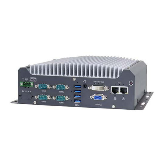
Front Panel I/O The FES7501 I/O panel features two gigabit Ethernet ports, four USB3.1 Gen1 ports, one VGA connector, one DVI-D connector and four serial ports. Item Description Power button Use this button to turn on or shutdown the system. -
Page 15: Power Button
2.2.1 Power Button The power button is a non-latched switch for ATX mode on/off operation. Press to turn on the system, PWR LED should light up and to turn off, you can either issue a shutdown command in the OS, or just press the power button. In case of system halts, you can press and hold the power button for 5 seconds to force-shutdown the system. -
Page 16: Ethernet Port
2.2.2 Ethernet Port The system offers two GbE ports on its I/O panel. The GbE ports are marked in blue/ ® ® and are implemented with Intel I219-LM/ Intel I210-IT controllers, respectively. Each port has one dedicated PCI Express link for maximum performance. When an Ethernet connection is established, the LED indicators on the RJ45 connector represents the following connection statuses: Active/Link LED... -
Page 17: Reset Button
2.2.3 Reset Button The reset button can be used to manually reset the system in case of abnormal condition. To avoid unexpected operation, the reset button is hidden behind the front panel. You need to use a pin-like object to push the reset button. 2.2.4 DVI Port The system has one DVI-D connector on its I/O panel to support independent display... -
Page 18: Vga Port
2.2.5 VGA Port FES7501 has dual display outputs on its front panel for connecting different displays according to your system configuration. VGA connector is the most popular way for connecting a display. To support multiple display outputs and achieve best DVI output resolution in Windows, you need to install corresponding graphics driver. -
Page 19: 4-Pole 3.5Mm Microphone-In/ Speaker-Out Jack
2.2.7 4-Pole 3.5mm Microphone-in/ Speaker-out Jack There is a female 4-pole audio jack for headphone (speaker) output and microphone input. To utilize the audio function in Windows, you need to install corresponding drivers. Please refer to the section, Driver Installation. 2.2.8 CMOS Reset Button The CMOS Reset button is used to manually reset the motherboard BIOS in case of... -
Page 20: 2.2.10 Com Port
2.2.10 COM Port The system provides four COM ports for communicating with external devices. These COM ports are implemented using industrial-grade ITE8786 Super IO chip (-40 to 85°C) and provide up to 115200 bps baud rate. COM1 and COM2 are software-configurable RS-232/422/485 ports. COM3 and COM4 are standard 9-wire RS-232 ports. -
Page 21: 2.2.11 3-Pin Terminal Block For Dc Input
2.2.11 3-Pin Terminal Block for DC Input The system allows DC power input from 8 to 35V via a 3-pin pluggable terminal block, which is ideal for field usage where DC power is provided. The screw clamping mechanism of the terminal block offers utmost reliability when wiring DC power. Symbol Description Remote... -
Page 22: Internal I/O Functions
Internal I/O Functions In addition to I/O connectors on the front panel, the system also provides internal on-board connectors, such as remote on/off control, LED status output, internal USB 2.0 ports and etc. In this section, we’ll illustrate these internal I/O functions. 2.3.1 Status LED Output &... - Page 23 Pin Definition Pin# Definition Description WDT_LED- [Output] Watchdog timer indicator, flashing when watchdog timer is started. WDT_LED+ Un-used pin HDD- [Output] Hard drive indicator, flashing when SATA hard drive is active. HDD+ Power_LED- [Output]System power indicator, on if system is turned on, off if system is turned off.
-
Page 24: 2280 (M Key) Slot For Ssd (Sata Signal Only)
2.3.2 M.2 2280 (M Key) Slot for SSD (SATA Signal Only) The system has an M.2 2280 slot (SATA signal only) for you to install an M.2 SATA SSD. NOTE The M.2 slot is only compatible with SATA signal M.2 SSD only. - Page 25 M.2 2280 M Key Pin Definition Pin # Signal Pin # Signal +3V3 +3V3 DAS/DSS_N +3V3 +3V3 +3V3 +3V3 SATA-B+ SATA-B- SATA-A- SATA-A+ Mechanical Key +3V3 +3V3 +3V3...
-
Page 26: Single Dram So-Dimm Slot
2.3.3 Single DRAM SO-DIMM Slot The system motherboard supports one 260-pin SODIMM socket for installing one DDR4-2666/ 2400 memory module up to 32GB capacity. -
Page 27: Mini-Pcie Slot
2.3.4 mini-PCIe Slot The system provides a mini-PCIe socket compliant with mini-PCIe specification rev. 1.2. There are plenty of off-the-shelf mini-PCIe modules with versatile capabilities. By installing a mini-PCIe module, your system can have expanded features such as WIFI, GPS, CAN bus, analog frame grabber, etc. - Page 28 mini-PCIe slot definition Pin # Signal Pin # Signal WAKE# +3.3Vaux COEX1 COEX2 +1.5V CLKREQ# UIM PWR UIM DATA REFCLK- UIM CLK REFCLK+ UIM RESET UIM VPP Mechanical Key Reserved* (UIM C8) Reserved* (UIM C4) W DISABLE# PERST# PERn0 +3.3Vaux PERp0 +1.5V SMB CLK...
-
Page 29: 2242 B Key And Sim Card Slot
2.3.5 M.2 2242 B Key and SIM Card Slot The system has a M.2 2242 (indicated in blue) slot that works in cooperation with a SIM slot (indicated in red). By installing a M.2 module, you can install a 3G/ 4G module with a SIM card for internet access via your service provider’s 3G/ 4G network. - Page 30 M.2 Slot Pin Definition Pin # Signal Pin # Signal USB_D+ USB_D- UIM1-RESET UIM1-CLK UIM1-DATA UIM1-PWR PERn0 PERp0 PETn0 PETp0 PERST_N REFCLKN REFCLKP- IM1_DETECT RESET_N...
-
Page 31: Sata Port
2.3.6 SATA Port The system provides one SATA port which support Gen3, 6 Gb/s SATA signals. The SATA port is composed of a 7-pin SATA connector (indicated in blue) and a 4-pin power connector (indicated in red). A dedicated cable is shipped with the system to provide a standard 22-pin SATA connector to the installed device. -
Page 32: Internal Usb Port
2.3.7 Internal USB Port The system provides one additional USB port internally on the PCBA. It supports standard USB 2.0 signals. You can utilize this USB port to connect a USB protection dongle inside the chassis of the controller. WARNING DO NOT use a USB flash drive with a metallic enclosure that conducts electricity which may short-circuit the motherboard! -
Page 33: System Installation
System Installation Before disassembling the system enclosure and installing components and modules, please make sure you have done the following: It is recommended that only qualified service personnel should install and service this product to avoid injury or damage to the system. Please observe all ESD procedures at all times to avoid damaging the ... -
Page 34: Disassembling The System
Disassembling the System To access system internal components, the system needs to be disassembled. To disassemble the system enclosure, you need to remove screws on the I/O panel, removable and side panel. On the I/O panel side, unscrew the three (3) screws shown below. Unscrew the four (4) screws shown on top of the enclosure. - Page 35 Unscrew the three (3) screws (indicated in blue) to remove the rear panel. Unscrew the four (4) screws at the bottom of the system. Gently lift and remove the bottom panel.
-
Page 36: Cpu Installation
CPU Installation DO NOT remove the CPU from its container / tray before it is ready to be installed. With the enclosure panels removed, to access the CPU socket, please do the following: i. If you are installing a CPU for the first time, remove the four (4) screws indicated in blue. - Page 37 Remove the CPU from its container/ tray. Match the two notches on the side to the protrusions in the socket, gently lower the CPU into the socket. Locate the CPU retention bracket from the accessory box. Place the retention bracket on the CPU and hold it in place.
- Page 38 Turn the motherboard around and secure the bracket by tightening two M3 P-head screws. Hold CPU bracket firmly and turn the motherboard around Secure two M3 P-head screws Remove all protective films on the thermal pads on the heatsink.
- Page 39 With the four motherboard standoffs aligned, gently lower the motherboard onto the heatsink.
- Page 40 Secure the four (4) M3 P-head motherboard screws (indicated in blue) and from the accessory box, five (5) M3 spring screws (indicated in red). Gradually tighten the five screws in the following order for even pressure. Secure five CPU/ heatsink spring screws in order Securing the motherboard Reinstall the system enclosure...
-
Page 41: Ddr4 So-Dimm Installation
DDR4 SO-DIMM Installation There is a single memory SO-DIMM slot on the motherboard that supports up to 32GB DDR4-2666/ 2400. Please follow the procedures below to replace or install the memory modules. 1. Please refer to the section “Disassembling the System”, you may not need to completely dismantle the system to gain access to the memory module slots. - Page 42 5. When reinstalling the enclosure, please make sure the protective film on the thermal pad (located on the hard drive bracket) has been removed so it can properly make contact with the DRAM module. Reinstall the system enclosure and panel when done. If you need to install other components, please refer to respective sections.
-
Page 43: 2280 Sata Ssd Installation
M.2 2280 SATA SSD Installation The system has an M.2 2280 slot (SATA signal only) for you to install an M.2 2280 SATA SSD for fast read and write performance. For installation, please refer to the following instructions. Please refer to the section “Disassembling the System”, you may not need to completely dismantle the system to gain access to the M.2 slot. - Page 44 Gently press down and secure the module with an M3 P-head screw. Reinstall the system enclosure and panel when done. If you need to install other components, please refer to respective sections.
-
Page 45: Module Installation
M.2 Module Installation The system has a M.2 slot (indicated in blue) coupled with SIM socket (indicated in red) for installing 3G/ 4G module. For installation, please refer to the following instructions. Please refer to the section “Disassembling the System”, you may not need to completely dismantle the system to gain access to the M.2 slot and SIM socket. - Page 46 Before installing the M.2 module, you need to insert the SIM card. Slide the SIM slot towards the outside of the motherboard and lift the SIM card holder. Insert the SIM card (pins facing up), and slide it towards the left to lock the SIM card in-place.
- Page 47 Insert the M.2 module on a 45 degree angle into the M.2 slot. Secure the M.2 module. Reinstall the system enclosure and panel. If you need to install other components, please refer to respective sections.
-
Page 49: Mini-Pcie Module Installation
mini-PCIe Module Installation The system has one mini-PCIe slot. To install a mini-PCIe module, please refer to the following instructions. Please refer to the section “Disassembling the System”, you may not need to completely dismantle the system to gain access to the mini-PCIe slot. Insert the module on a 45 degree angle. - Page 50 Gently press down and secure the module with two M2.5 P-head screws Reinstall the system enclosure and panel. If you need to install other components, please refer to respective sections.
-
Page 51: Hdd/ Ssd Installation
HDD/ SSD Installation The system has one SATA port, you can install a 2.5” HDD/ SSD or a 3.5” HDD into the system. Please refer to the following instructions: 3.7.1 2.5” HDD/ SSD Installation 1. Please refer to the section “Disassembling the System”... - Page 52 4. Connect 2.5" HDD/ SSD to the motherboard with SATA (indicated in blue) and power (indicated in red) cable. Cable connections SATA/ power connectors Reinstall the system enclosure and panel when done. If you need to install other components, please refer to respective sections.
-
Page 53: Hdd Installation
3.7.2 3.5” HDD Installation 1. Please refer to the section “Disassembling the System” to gain access to SATA port. 2. Secure 3.5” HDD on the HDD/SSD bracket with #6-32 flat-head screws. 3. Secure 3.5” HDD and the bracket on the chassis with M3 flat head screw. - Page 54 4. Connect 3.5" HDD/ SSD to the motherboard with SATA (indicated in blue) and power (indicated in red) cable. Cable connections SATA/ power connectors Reinstall the system enclosure and panel when done. If you need to install other components, please refer to respective sections...
-
Page 55: Installing The System Enclosure
Installing the System Enclosure To reinstall the system enclosure, please follow the steps below: With the heatsink upside-down, gently lower the enclosure. Place the four rubber stand and secure the four (4) screws at the bottom of the system panel. Secure the three (3) screws on the rear panel. - Page 56 Turn the system around with the heatsink on top, secure the four(4) screws at the top of the enclosure. Secure the three(3) screws on the IP panel to complete the enclosure installation procedure.
-
Page 57: Mounting
Acnodes provides versatile mounting methods for FES7501. You can use built-in wall-mounting brackets to mount it on the wall. Acnodes also offers optional DIN- rail mounting kit to mount it on a DIN-rail. To mount FES7501, please refer to the instructions listed below. -
Page 58: Installing Din-Rail Mounting Kit (Optional)
M4 flat-head screws first, and then fix the bracket assembly to the FES7501 controller with another four M4 screws. This option can be useful if you want to deploy it inside an equipment cabinet where DIN-rail is... -
Page 59: System Configuration
NOTE Not all BIOS settings will be discussed in this section. If there is a particular BIOS setting you are after but is not discussed in this section, please contact Acnodes. -
Page 60: Com Port Configuration
4.1.1 COM Port Configuration There are four COM ports for FES7501. The system’s COM1 and COM2 support RS-232 (full-duplex), RS-422 (full-duplex) and RS-485 (half-duplex) mode, while COM3 and COM4 support RS-232 mode only. You can set the COM1/ COM2 operating mode via BIOS settings. -
Page 61: Com Port High Speed Mode
4.1.2 COM Port High Speed Mode The high speed mode of each COM port effectively allows for the port's baud rate generator to operate at 8x the speed with an effective baud rate of 921,600 bps (115,200 x 8). Please refer to the following instructions on how to enable the high speed mode for your COM port (COM1 used as an example). -
Page 62: Power On After Power Failure Option
4.1.3 Power On After Power Failure Option This option defines the behavior of system when DC power is supplied. Value Description S0 – Power On System is powered on when DC power is supplied. S5 – Power Off System is kept in off state when DC power is supplied. To set “Power On after Power Failure”... -
Page 63: Sata Configuration
4.1.4 SATA Configuration The system SATA controller supports two (2) operating modes: SATA and AHCI modes. AHCI mode, which exposes SATA's advanced capabilities such as hot swapping and native command queuing, is supported in several later version of operating systems. Recommended SATA controller mode settings: If you’re using Windows Vista, Windows 7/ 8/ 10, or Linux kernel 2.6.19 or later, ... -
Page 64: Power & Performance (Cpu Sku Power Configuration)
4.1.5 Power & Performance (CPU SKU Power Configuration) The system supports Intel 9 Gen Coffee Lake LGA1151 CPUs. A unique feature, “SKU Power Config” is implemented in BIOS to allow users to specify user-defined SKU power limit. Although the system is designed to have best thermal performance with CPUs of 35W TDP, you can install a 65W CPU and limit its SKU power to 35W to obtain more computing power. -
Page 65: Wake On Lan Option
4.1.6 Wake on LAN Option Wake-on-LAN (WOL) is a mechanism which allows you to turn on your system via Ethernet connection. To utilize Wake-on-LAN function, you have to enable this option first in BIOS settings. Please refer to “Powering On Using Wake-on-LAN” to set up the system. -
Page 66: Boot Menu
4.1.7 Boot Menu The Boot menu in BIOS allows you to specify the system’s boot characteristics by setting bootable device components (boot media) and method. Or, you may press F12 upon system start up and select a device you wish boot from. -
Page 67: Boot Type (Legacy/ Uefi)
4.1.8 Boot Type (Legacy/ UEFI) The system supports both Legacy and Unified Extensible Firmware Interface (UEFI) boot modes. UEFI is a specification proposed by Intel to define a software interface between operating system and platform firmware. Most modern operating systems, such as Windows 7/8/10 and Linux support both Legacy and UEFI boot modes. -
Page 68: Add Boot Options
4.1.9 Add Boot Options The Add Boot Options dedicates the boot sequence order of a newly added device (eg. USB flash drive). The setting allows you to set the newly added device to boot first or as the last device on the list. To set Add Boot Options: When system boots up, press F2 to enter BIOS setup utility. -
Page 69: 4.1.10 Watchdog Timer For Booting
4.1.10 Watchdog Timer for Booting The Watchdog timer setting in the BIOS ensures a successful system boot by specifying a timeout value. If the Watchdog timer is not stopped and expires, the BIOS will issues a reset command to initiate another boot process. There are two options in BIOS menu, “Automatically after POST”... -
Page 70: 4.1.11 Legacy/ Uefi Boot Device
4.1.11 Legacy/ UEFI Boot Device When you wish to set a designated boot device, you may set it as the first device to boot in Legacy or UEFI Boot Device setting. Or if you wish to manually select a boot device, you may do so by pressing F12 when the system boots up. -
Page 71: Os Support And Driver Installation
RAID. For optimum operation, it is the users’ responsibility to manually check for new drivers and upgrades! Acnodes may remove or update operating system compatibility without prior notice. Please contact us if your operating system of choice is not on the list. -
Page 72: Driver Installation
Driver Installation The system comes with a “Drivers & Utilities” DVD that offers “one-click” driver installation process or you can choose to install driver manually. 5.2.1 Install Drivers Automatically The system comes with a “Drivers & Utilities” DVD that offers “one-click” driver installation process. -
Page 73: Driver Installation For Watchdog Timer Control
Driver Installation for Watchdog Timer Control Acnodes provides a driver package which contain function APIs for Watchdog Timer control function. You should install the driver package (WDT_DIO_Setup.exe) in prior to use these functions. Please note that you must install WDT_DIO_Setup_v2.3.0.0 or later versions.
Need help?
Do you have a question about the FES7501 and is the answer not in the manual?
Questions and answers