Table of Contents
Advertisement
Quick Links
User Manual
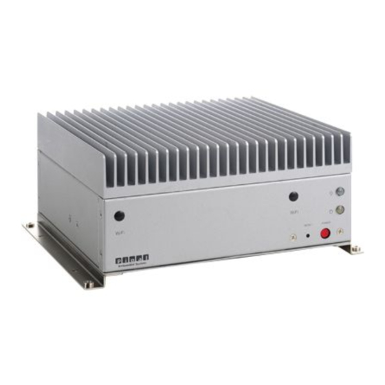
FES2215: Fanless Embedded System Atom D2550
Dual Core 1.86GHz Processor
14628 Central Ave,
Chino, CA 91710
tel:909.597.7588, fax:909.597.1939
FES2215
Fanless Embedded System
© Copyright 2013 Acnodes, Inc.
All rights reserved. Product description and product specifications
are subject to change without notice. For latest product information,
please visit Acnodes' web site at www.acnodes.com.
Advertisement
Table of Contents

Related Manuals for Acnodes FES2215


Summary of Contents for Acnodes FES2215
-
Page 1: User Manual
FES2215 Fanless Embedded System User Manual FES2215: Fanless Embedded System Atom D2550 Dual Core 1.86GHz Processor © Copyright 2013 Acnodes, Inc. All rights reserved. Product description and product specifications 14628 Central Ave, Chino, CA 91710 are subject to change without notice. For latest product information, tel:909.597.7588, fax:909.597.1939... -
Page 2: Copyright
Copyright This publi cati on c ontains inform ation that is prot ected by copyright. N o part of it m ay be reproduced i n any form or by any m eans or used to make any transform ation/adaptation without the prior written permission from the copyr ight holde rs. -
Page 3: Safety Measures
© Copyright 2013 Acnodes, Inc. All rights reserved. Product description and product specifications 14628 Central Ave, Chino, CA 91710 are subject to change without notice. For latest product information, tel:909.597.7588, fax:909.597.1939 please visit Acnodes’ web site at www.acnodes.com. -
Page 4: Table Of Contents
4-2 Expansion Sl ot ( PCI Slot)……………………………………………………… ………………………… © Copyright 2013 Acnodes, Inc. 14628 Central Ave, All rights reserved. Product description and product specifications Chino, CA 91710 are subject to change without notice. For latest product information, tel:909.597.7588, fax:909.597.1939 please visit Acnodes’ web site at www.acnodes.com. -
Page 5: Chapter 1: Introduction
800/ 1066 w hile as t he gr aphic clock speed of 64 0 MHz. FES2215 suppor ts for dual display of VGA and HDMI . Fu rt her mor e, w hile as t he new FES2215 is equipped of NM10 South Br idge Chipset , w hich... -
Page 6: Product Specification
1-2 Product Specification Processor & Chipset Sup por t Atom D2 550 D ual-core 1.86 GHz low p ower Pro cesso r NM 10 South Bridge Chip set Graphic E ngine Graphic core 640 Mhz Sup por t AVC/ H.264, VC1/ WMV9, MPEG2 HW engine ... - Page 7 Front Panel Extend I/O Ports Power & HDD Led. Power & System, Power & Reset b utton Rear Panel E xtend I/O Ports Screw-Lo ck DC po wer input con nector 2 DB-9 as 1 for RS-23 2/422/485 & 1 for RS-232, 1 RJ-45 for RS-232 ...
-
Page 8: System Block Diagram
1-3 System Block Diagram FE S 2215... -
Page 9: Me Chanical D Iagram
1-4 Mechanical Diagrams FES 2215... - Page 10 1-5 Front & Rear panel Front Panel Rear Panel...
-
Page 11: Front Panel Pin Definition
2-1 Front panel Pin Definition 1. Power On/ Off Button 2. Power Reset Button 3. Power & HDD LED 2-2 Rear Panel Pin Definition... - Page 12 2. COM 1 (DB-9): RS-23 2/ 422/ 4 85 [refe r to P.17-18, N o. 8 jumper setting] RS-232 R S-422 R S-486 D CD# RT X+ Not U sed T XD RTX- DT R# Not U sed G ND DSR# Not Used Not U sed...
-
Page 13: Internal Pin Definition & Jumper Settings
2-3 Internal Pin Definition & Jumper Settings 2-3.1 Main Board Top View... -
Page 14: 2-3.2 Mai N Board P In Definiti
2-3.2 M ain Board P in Definition... -
Page 15: 2-3.3 Jum Per Setting
2-3.3 Jumper Settings 1. Clear CM ON S Jumper (CLRCMOS1 ) [refer to P.13, N o. 1 6] It allows you to clear t he data in CM OS. To clear and reset the system parame ters to default se tup, please turn of f the computer and unpl ug the pow er cord f rom the pow er supply. Af te r wai ting for 15 seconds, use a jumpe r cap to short pin 2 and pin 3 on CLRCM OS1 for 5 seconds. - Page 16 7. Panel Resolution Se lection (1 2-pin JLVD_ GPIO1) [refer to P.1 3, N o. 2 9] 8. SET COM Por ts (10 -pin SET_ CM 1,2 ) [refer to P.1 3, No. 1 ] (10 -pin SET_ CM 4,5 ,6) [refer to P.13 , N o.
- Page 17 (COM 1 Pin1 & Pin 9 Function Setting) Item Pin 1 Fun ction Connector SET_COM1 Jumper S etti ng Config. 1 Pi n 1 & Pi n 3 short, Pin 5 & 7 & 9 NC Provide +12V Power Source Config.
- Page 18 10. USB 2.0 Ports (4-pin USB 4,5) [refer to P.13, N o. 11 ] (4-pin USB6 ) [refer to P.13, N o. 12] 11. System Panel Header (9-pin PANEL 1) [refer to P. 13, N o. 15] Connect the powe r switch, rese t switch and system status indicator on the chassis to this header according to the pin assignments below.
- Page 19 13. Front Panel Audio Header (9-pin HD_ AUDIO1) [refer to P.13, No. 25 ] 14. DC 12V Power Connector (4-pin DC 12V 1) [re fer t o P.1 3, No. 3 ] 15. COM Port 4 ,5 ,6 (10-pin COM 4,5,6) [refer to P.
- Page 20 16. Print Port Header (25-pin LPT1) [re fer to P.13, N o. 9] 17. LVD S Con (40 -pin LV DS1) [re fer to P.13, N o. 2] 18. Output Power (4-pin SATA_ PWR1 ) [refer to P.13, No. 7]...
- Page 21 19. Digital I/O He ader (10 -pin JG PIO1) [re fer to P.13 , No. 13 ] 20. Panel Brightness and Speaker Volume Control (7-pin BLT_VOL1) [refer to P.1 3, No. 2 1] 21. Panel BackLight Inve rte r Connector (6-pin BLT_PWR2) [re fer to P.1 3, No.
-
Page 22: Chapter 3: Uefi Setup Utility
Chapter 3: UEFI Setup Utility 3-1 Introduction This se ction explains how to use the U EFI SETUP U TILITY to configure yours syste m. The UEFI chip on the m otherboard stores the U EFI SETUP U TILITY. You may run the UEFI SETUP U TILITY w hen you start up the computer. -
Page 23: Main Screen
3-2 Main Screen Whe n you enter the UEFI SETUP UTILITY, the Main screen wil l appear and display the syste m ove rview. -
Page 24: Advanced Screen
3-3 Advanced Screen In this se ction, you m ay set the confi gurati ons f or the foll owing i tem s: CPU Configuration, Chipset Configuration, Storage Conf igurati on, Super IO Configuration, A CPI Configuration, U SB Conf iguration and Voltage Conf iguration. Se tting wrong values in this se ctio may cuase the system to malfunction. - Page 25 3-3.1 CPU Configuration Intel Hyper T hre ading Technology To enabl e this feature, it requi res a c ompute r system with an Intel processor that supports Hyper- Threading technol ogy and an operating syste m that includes optimization for this te chnol ogy, such as Mi crosoft®...
- Page 26 3-3.2 Chipset Configuration Set Pane l Type by Use this to c onf igure Set P anel Type.The Default value is [UEFI Setup]. Panel Type Sele ction Use this to sele ct panel type . The default va lue i s [1366 x768/ 18-bi t/ 1 -ch/LED ]. ACPI H PET Table Use this item to enable or disable ACPI HPET Table.
- Page 27 3-3.3 Storage C onfiguration Onboard SATAII M ode Use this to sele ct SATA 2 m ode. Confi gurati on options: [IDE Mode], [AHCI Mode] and [D isabled]. The default value is [IDE Mode ]. ACHI (Advanced Host Controller Interfac e) suppor ts NCQ a nd other new features that will improve SATA disk perfor mance but IDE mode does not have these advantage.
- Page 28 3-3.4 S uper IO Configuration COM 1 Configuration Use this to set parameters of CO M1 . COM 2 Configuration Use this to set parameters of CO M2 . COM 3 Configuration Use this to set parameters of CO M3 . COM 4 Configuration Use this to set parameters of CO M4 .
- Page 29 3-3.5 ACP I Configuration Suspe nd to RAM Use this item to sel ect whether to auto-detect or disable the Suspend-to-RAM feature. Select [Aut o] wi ll e nable this fe ature if the O S supports i t. S3 V ideo Repost Use this to enable/disable S3 V ideo Repost.
- Page 30 3-3.6 US B Configuration USB 2.0 Controller Use this item to enable or disabl e the use of USB 2 .0 control ler. Legacy U SB Suppor t Use this option to sele ct legacy support for USB devices. There are four c onfiguration opt ions: [Enabled], [Auto], [Disabled] a nd [U EFI Setup Only].
- Page 31 3-3.7 Voltage Configuration DRM A Voltage Use this item to sel ect DRM A Voltage . The def ault value is [A uto].
-
Page 32: Hardware Health Event Monitoring Screen
3-4 Hardware Health Event Monitoring Screen In this section, it al low s you to moni tor the status of the ha rdware on your system , i ncl uding the param ete rs of the CP U tem perature, mothe rboard tem pe rature, CPU fan speed, chassi s fan spe ed, and the critical voltage. -
Page 33: Boot Screen
3-5 Boot Screen In this section, it wi ll display the avai lable devices on your system for you to conf igure the boot setti ngs and the boot priority. Setup Prom pt T imeout Thi s shows the num ber of seconds to wait for setup activation key. 6553 5 ( 0XFFFF) m eans i ndefinite wa iting. -
Page 34: Security Screen
3-6 Security Screen In this section, you may se t, change or cl ear the supervisor/ user password for the system. -
Page 35: Exit Screen
3-7 Exit Screen Save Changes and Exit When you sele ct thi s optino, it wil l pop-out the fol lowi ng m essage, “Save configuration changes and exit setup?” Select [OK] to save the changes and exit the UEFI SETUP U TILITY. Discard Changes and Exit When you sele ct thi s option, it wi ll pop-out the following message, “Di scard changes and exi t se tup? ”... -
Page 36: Chapter 4: Installation Guide
Chapter 4: Installation Guide 4-1. Memory Modules (SO-DIMM) Pipal 2215 provide s two 240-pin DDR3 SO -DIMM slots. - It is NO T al low ed to install a DDR or DDR2 m emory module into a DDR 3 slot; otherw ise, the m otherboard and SO-DIMM m ay be damaged. -
Page 37: Expansion Slot (Pci Slot)
4-2. Expansion Slot (PCI Slot) There i s 1 Mi ni-PCI-E ex pansi on slot for FES 22 15. PCI Slot: The P CI sl ot is use d to instal l an expansion car d that has 32 -bit P CI interf ace. 4-2.1 Installing an expansion card STEP 1: Before instal ling the e xpansi on card, ple ase make sure that the power supply is switche d off or the powe r cord i s unpl ugged.
Need help?
Do you have a question about the FES2215 and is the answer not in the manual?
Questions and answers