
Related Manuals for BodyCraft EliteV4


Summary of Contents for BodyCraft EliteV4
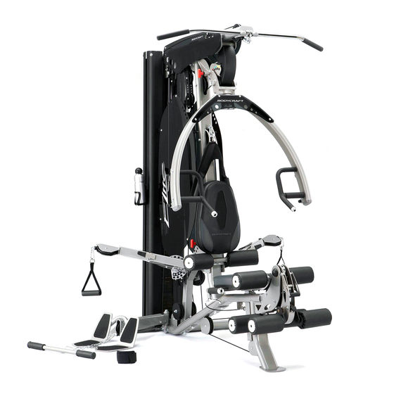
- Page 1 ELITE STRENGTH TRAINING SYSTEM OWNERS MANUAL MA605C Recreation Supply Inc. P.O. BOX 181 EliteV4 Model No. BODYCRAFT Sunbury, OH 43074 is a division of Recreation Supply...
-
Page 2: Important Safety Notes
8. Make certain all cables are seated within the pulleys before every use. 9. Exercise with care to avoid injury. 10. If you are unsure about the proper use of the BODYCRAFT Elite strength training system call your local BODYCRAFT dealer or our customer service department. - Page 3 Gym Placement Planner If possible, please take advantage of the corner fit design. WALL 68.75" 62.50" HEIGHT 82.50" 84.75" with Leg Press option Important Notes and Tips: Recommended Tools for Assembly 1. Do not tighten any bolts until instructed. 2. Two people are reguired for the safe assembly of the gym.
- Page 4 OVERVIEW 138 184 134 161 138 163 113 149 163 158...
-
Page 5: Parts List
PARTS LIST NO. DESCRIPTION QTY. MAIN FRAME REAR STABILIZER FRONT UPRIGHT TOP FRAME FOOT PLATE CONNECTOR GUIDE ROD PRESS ARM RIGHT HANDLE OF PRESS ARM (all pre-assembled) LEFT HANDLE OF PRESS ARM (all pre-assembled) PRESS ARM SUPPORT ROTOR OF PRESS ARM SUPPORT (all pre-assembled) SEAT ADJ. - Page 6 PARTS LIST NO. DESCRIPTION QTY. STEEL SPACER FOR SWIVEL CABLE ARM END (all pre-assembled) STEEL SPACER FOR PRESS ARM (all pre-assembled) R8ZZ BEARING FOR LEG EXTENSION ARM (all pre-assembled) STEEL SPACER FOR LEG EXTENSION ARM (all pre-assembled) COLLAR (all pre-assembled) AXLE COLLAR (all pre-assembled) HOOK PLATE (all pre-assembled) RIGHT SIDE ACRYLIC PANEL...
- Page 7 PARTS LIST NO. DESCRIPTION QTY. RIGHT TRIM OF CABLE ARM (all pre-assembled) LEFT TRIM OF CABLE ARM (all pre-assembled) CLIP CAP FOR CABLE ARM (all pre-assembled) 1/2" STOPPER (all pre-assembled) MAIN FRAME STOPPER (all pre-assembled) NUT FOR LEG EXTENSION (all pre-assembled) PIN BOLT FOR LEG EXTENSION (all pre-assembled) LEG EXTENSION LARGER SPRING...
- Page 8 PARTS LIST NO. DESCRIPTION QTY. 3/8" X 1" HEX THREADED BOLT 3/8" X 1" INNER HEX SCREW (all pre-assembled) 3/8" X 3/4" INNER HEX SCREW (all pre-assembled) 3/8" X 109.5L FLAT PIN BOLT 3/8" X 75L FLAT PIN BOLT 3/8" X 2-3/4" HEX BOLT 3/8"...
- Page 9 STEP 1 ASSEMBLE MAIN FRAME TO EASE THE ASSEMBLY PROCESS. DO NOT TIGHTEN ANY BOLTS UNTIL INSTRUCTED. 1. Attach the REAR STABILIZER (2) to the MAIN FRAME (1) using two 1/2" X 5" HEX BOLTS (129) and two 1/2" NYLA-NUTS (169). 2.
- Page 10 STEP 2 TOP FRAME AND WEIGHT STACK ASSEMBLY 1. Attach the two GUIDE RODS (6) to the stack mount welded to the REAR STABILIZER (2) using two 3/8" X 3/4" HEX THREADED BOLTS (180). Tighten these bolts. 2. Slide one RUBBER CUSHION (110) onto each GUIDE ROD (6) and push to the bottom.
- Page 11 STEP 3 ASSEMBLE CABLE ARM Remember to keep all BOLTS loose to ensure the holes will align easily. 1. Attach the CABLE ARM ASSEMBLY (18) to the MAIN FRAME (1), using two 1/2" X 3-1/4" HEX BOLTS (130) four 1/2" SMALLER WASHERS (161) and two 1/2" NYLA- NUTS (169).
- Page 12 STEP 4 LEG EXTENSION AND SEAT ASSEMBLY TO EASE THE ASSEMBLY PROCESS, spray window cleaner or water TIP! into the holes of the FOAM ROLLERS (40) before sliding onto shafts. 1. Attach the R and L LEG EXTENSION ARMS (21R & 21L) along with RATCHET (32) to the preassembled LEG EXTENSION ASSEMBLY (20) as shown.
- Page 13 STEP 4 LEG EXTENSION AND SEAT ASSEMLY Figure 1 1" 2" 3" 4" 5" 6" (inch)
- Page 14 STEP 5 PRESS ARM ASSEMBLY 1. Secure the PLASTIC COVER (74) to the front of the PRESS ARM SUPPORT (9) using one M5 X 63L SCREW (153). Attach the PRESS ARM SUPPORT (9) to the TOP FRAME (4) by aligning the holes and inserting the AXLE (35). Secure and tighten using two 1/2" LARGER WASHERS (160) and two 1/2"...
- Page 15 STEP 6 SEAT BACK ADJUSTER AND LEG HOLDER ASSEMBLY 1. Attach the SEAT BACK ADJUSTER (13) to the FRONT UPRIGHT (3), using one 3/8" X 5-1/4" HEX BOLT (133), two 3/8" LARGER WASHERS (163) and one 3/8" NYLA-NUT (170). Tighten this bolt until the SEAT BACK ADJUSTER (13) is snug against the FRONT UPRIGHT (3) to eliminate play.
- Page 16 STEP 7 INSTALL TOP CABLE TOP CABLE (82) Threaded End Ball End *Assemble cables and pulleys simultaneously.* On the following pages, when references are made regarding the LEFT, RIGHT and FRONT of the machine, the directions are as if you are seated in the gym with your back against the Back Pad. 1.
- Page 17 STEP 7 INSTALL TOP CABLE Fig. 1 Fig. 2 Fig. 3 1/2" STOPPERS (93) Pulley Sizes 4.5" (100) 4.5" (100) 4.5" (100) 4.5" (100) Fig. 4 4.5" (100) 4.5" (100) Welded Stop Plate T8,T10 3.5" (101) 4.5" (100) 4.5" (100) T10 4.5"...
- Page 18 STEP 8 AB CRUNCH CABLE INSTALLMENT AB CRUNCH CABLE (83) REMOVABLE END (83A) Bolt-end 1. See Fig. A1 Screw the Bolt-end of the AB CRUNCH CABLE (83) at least one-third of the way into the threaded receptor welded to the TOP FRAME (4). This Bolt-end is an adjustment point if needed once all of the cables have been installed.
-
Page 19: Step 9 Install Leg Extension Cable
STEP 9 INSTALL LEG EXTENSION CABLE LEG EXTENSION CABLE (84) Threaded End Steel Ball End 1. See Fig. E1 & E2 Hook the steel ball end of the LEG EXTENSION CABLE (84) into the groove in the LEG CURL CAM (22), and then route the cable in between two Pulleys E2 and E3 and secure using one 3/8"... -
Page 20: Connect Cable
STEP 10 INSTALL CONNECT CABLE CONNECT CABLE (85) Threaded End Threaded End 1. See Figs. C1 & C2 Screw the threaded end of CONNECT CABLE (85) into the SINGLE PULLEY BLOCK (24) and route the cable up and over Pulley C2 mounted on TOP FRAME (4), using one 3/8"... - Page 21 STEP 11 INSTALL CABLE ARM CABLE CABLE ARM CABLE (86) (preinstalled) Ball End Ball End 1. The CABLE ARM CABLE (86) is preinstalled in the CABLE ARM (16). Mount Pulleys P3 and P7 along with their PULLEY GUIDE BRACKET (27) to the CABLE ARM ASSEMBLY (18) as shown, using one 3/8"...
- Page 22 STEP 12 INSTALL LOW CABLE LOW CABLE (87) Ball End Steel Ball End If you have purchased the OPTIONAL LEG PRESS, DO NOT INSTALL the LOW ROW CABLE (87). Follow the instructions in the LEG PRESS box. 1. Route the LOW CABLE (87) under Pulley L1 mounted in the front of the FOOT PLATE CONNECTOR (5) using one 3/8"...
- Page 23 STEP 13 WEIGHT STACK SHROUDS & ACRYLIC PANELS 1. Attach the BOTTLE CAGE (68) to the RIGHT WEIGHT SHROUD (46R) using two M5 X 12L SCREWS (155), and two M5 NYLA-NUTS (172). Tighten. 2. Attach the WEIGHT SHROUD (45), hole oriented toward bottom, to the tabs welded on the REAR STABILIZER (2), and TOP FRAME (4) using four 5/16"...
- Page 24 STEP 13 WEIGHT STACK SHROUD & ACRYLIC PANEL...
-
Page 25: Step 14 Attach Accessories
STEP 14 ATTACH ACCESSORIES 1. Attach WATER BOTTLE (67) to the BOTTLE CAGE (68) and the LAT BAR (42) to TOP CABLE (82) and rest on Lat Bar Holder. 2. Attach AB CRUNCH STRAP (60) with CLIP (91) to the AB CRUNCH CABLE (83) and MULTIPLE D-RING SINGLE HANDLE (62) to CABLE ARM (16). - Page 26 The Cable Adjustment of ELITE GYM a. The Cables should be tightened to the point just before the Top Plate lifts off the stack. In other words, if the Top Plate is not resting on the stack, you will need to add length, or, if there is slack in the cables, you will need to shorten the cables.
-
Page 27: Strength Training
Guide Rods (6). Enjoy many years of a Fit Lifestyle. Thank you for purchasing the BodyCraft Elite Strength Training System. If you have any questions, please call your local BodyCraft dealer, call our customer service department at 800-990-5556 or at http://www.bodycraft.com.
Need help?
Do you have a question about the EliteV4 and is the answer not in the manual?
Questions and answers