Advertisement
QUESTION?
As a quality home gym supplier we are committed to your complete satisfaction. If you have
questions, or find missing or damaged parts, we will guarantee your complete satisfaction through
our authorized dealer service centers or our home office customer service department. Please call
your local dealer for assistance or BodyCraft at 800-990-5556 (9:00 AM - 5:00 PM). Our trained
technicians will provide immediate assistance to you, free of charge.
Bodycraft is a division of Recreation Supply Inc.
P.O. BOX 181
Sunbury, OH 43074
OWNERS MANUAL
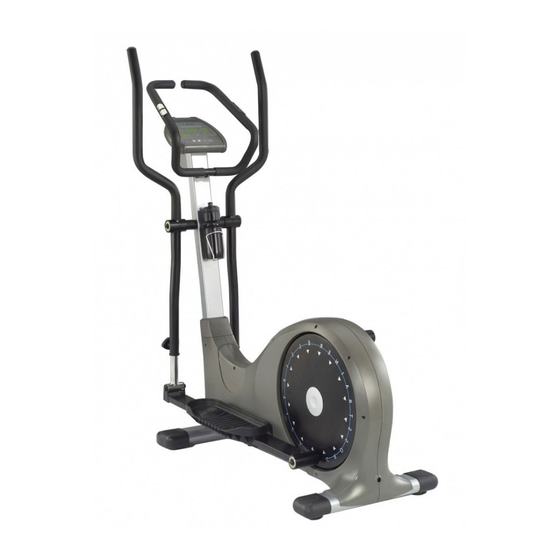
MODEL ECT-2100
ELLIPTICAL CROSSTRAINER
ECT-2100
Advertisement
Table of Contents

Related Manuals for BodyCraft ECT-2100


Summary of Contents for BodyCraft ECT-2100
-
Page 1: Owners Manual
Please call your local dealer for assistance or BodyCraft at 800-990-5556 (9:00 AM - 5:00 PM). Our trained technicians will provide immediate assistance to you, free of charge. -
Page 2: Before You Begin
4. Plug this product into a grounded outlet only. 5. Never operate a BodyCraft product if it has a damaged power cord, or if the cord is wet. Keep the power cord away from heat sources. Do not run the cord along side, or under this product. Do not use the power cord as a means to move this product. - Page 3 OVERVIEW...
-
Page 4: Parts List
PARTS LIST NO. DESCRIPTION QTY. MAIN FRAME FRONT STABILIZER BELT TENSION BRACKET FRONT UPRIGHT ASSEMBLY HANDLEBAR RIGHT FOOT PEDAL FRAME LEFT FOOT PEDAL FRAME RIGHT DUAL ACTION ARM LEFT DUAL ACTION ARM ELECTROMAGNET RIGHT WHEEL COVER SUPPORT LEFT WHEEL COVER SUPPORT ANGLE ADJUSTMENT TUBE REAR STABILIZER BELT SHAFT... - Page 5 PARTS LIST NO. DESCRIPTION QTY. PULSE CHIP 1" X 3" PEDAL ARM TUBE PLUG MAGNETIC FASTENER FASTENER OF BELT AXLE "U" SHAPED MAGNETIC DIVIDER M5 X 45mm HEX BOLT M6 X 16mm MACHINE BOLT M5 WASHER M5 NYLON NUT STRAIGHT MAGNETIC DIVIDER 6004 BEARING 6004ZB BEARING 6203 BEARING...
- Page 6 Step 1 Note: Save one of the packaging Styrofoam blocks to aid assembly. Open carton and unpack all parts. Check to ensure you have the following parts: 1. Main frame with plastic shrouds and pedal frames attached 2. Front Stabilizer 3.
- Page 7 Step 3 Insert the Angle Adjustment Tube (12) into the Right Dual Action Arm (7) and choose a height, then tighten the Triangle Knob (30). Repeat the procedure (and same height) for the Left Dual Action Arm (8). You will want to experiment with height adjustment to find the most comfortable stride. Step 4 Find the Handlebar (5).
- Page 8 Step 5 Connect the wires as shown in Figure E1. Connect the Upper Computer Cable (47) to the Computer Connecting Cable (67). Connect the Hand Pulse Cables (49) to the Pulse Connecting Cables (65). Push the cables down into the Upright as you bring the Computer down to attach it. Attach the Computer (23) to the top of the Upright (4), using four M5 X 10mm Dome Bolts (93).
- Page 9 Step 7 Attach the Bottle Holder (44) to the Front Upright (4) using two M5 X 10mm Dome Bolts (93). Step 8 Insert the Power Cord (41) into the barrel plug on the back side of Elliptical Crosstrainer. Then insert the Plug end into the wall outlet. The console should light up. If not, re-check plug and wall connections and make sure the wall outlet has power.
- Page 10 ECT-2100 Elliptical Crosstrainer Time Resistance Pulse Calories Strides Distance Resistance The readout displays resistance level, measured in Watts. Time The readout displays elapsed time if you start without first setting a time goal. Or, if you input a time goal before beginning, the readout displays time remaining to reach goal.
Need help?
Do you have a question about the ECT-2100 and is the answer not in the manual?
Questions and answers