
Subscribe to Our Youtube Channel
Related Manuals for Beckhoff PS2001-4810-0000


Summary of Contents for Beckhoff PS2001-4810-0000
- Page 1 Documentation | EN PS2001-4810-0000 Power supply 48 V DC, 10 A, 1-phase 2020-10-08 | Version: 1.0...
-
Page 3: Table Of Contents
Charging batteries ........................... 32 Series connection .......................... 32 Parallel use to increase power ...................... 32 Operation on two phases......................... 34 Use in a tightly sealed enclosure ..................... 34 Installation positions ........................ 34 5 Appendix .............................. 36 Accessories ............................. 36 Documentation issue status ...................... 37 Support and Service ........................ 38 PS2001-4810-0000 Version: 1.0... - Page 4 Table of contents Version: 1.0 PS2001-4810-0000...
-
Page 5: Overview
• DC-OK relay contact • Current-sharing function for parallel use The power supply PS2001-4810-0000 is a single-phase, 48 V DC power supply with an output current of 10 A and an output power of 480 W. On the input side, the device features a wide-range input, Active Power Factor Correction (PFC) and inrush current limiting. -
Page 6: Foreword
, XFC , XTS and XPlanar are registered trademarks of and licensed by Beckhoff Automation GmbH. Other designations used in this publication may be trademarks whose use by third parties for their own purposes could violate the rights of the owners. -
Page 7: Safety Instructions
All the components are supplied in particular hardware and software configurations appropriate for the application. Modifications to hardware or software configurations other than those described in the documentation are not permitted, and nullify the liability of Beckhoff Automation GmbH & Co. KG. Personnel qualification This description is only intended for trained specialists in control, automation and drive engineering who are familiar with the applicable national standards. - Page 8 Foreword Safety instructions and installation requirements for PS2001-4810-0000 power supply unit DANGER Danger of electric shock, fire, injuries, injuries resulting in death! • Do not use the power supply without proper earthing (protective conductor). Use the terminal at the input terminal strip for the earth connection, not one of the screws on the housing.
- Page 9 • The maximum ambient air temperature is +70°C (+158°F). The operating temperature corre- sponds to the ambient or ambient air temperature, per definition at 2 cm below the device. • The device is designed for operation in the relative humidity range between 5% and 95%. PS2001-4810-0000 Version: 1.0...
-
Page 10: Terminology And Abbreviations
50 Hz. AC 120 V parameters are valid for a mains frequency of 60 Hz. A keyword indicating a choice without implied preference. shall A keyword indicating a mandatory requirement. should A keyword indicating a choice with a clearly preferred method of implementation. Version: 1.0 PS2001-4810-0000... -
Page 11: Technical Data, Mounting, Wiring
*) The power factor is the ratio of real (or active) power to apparent power in an AC circuit. **) The peak factor is the mathematical ratio of the peak value to the RMS value of the input current waveform. Fig. 1: Input voltage range; switch-on behavior definitions PS2001-4810-0000 Version: 1.0... - Page 12 Technical data, mounting, wiring Fig. 2: Input current over output current; power factor over output current Version: 1.0 PS2001-4810-0000...
-
Page 13: Dc Input
• Connect the positive pole to L and the negative pole to N. • Connect the PE terminal to the protective conductor or machine ground. Fig. 3: Wiring for DC input PS2001-4810-0000 Version: 1.0... -
Page 14: Input Inrush Current
AC 100V AC 120V AC 230V Input inrush Max. 15A 5.5A temperature-independent peak peak peak current Typ. 12A 4.5A peak peak peak Inrush energy Max. 1A²s 1A²s 1A²s Fig. 4: Typical switch-on behavior at nominal load, 25°C ambient temperature Version: 1.0 PS2001-4810-0000... -
Page 15: Output
2s. The output is then switched off for about 18 seconds before a new switch- on attempt is automatically made. This cycle is repeated as long as the overload persists. After the overload has been rectified, the device will operate normally. See Fig. Short circuit at output, hiccup mode, typ. PS2001-4810-0000 Version: 1.0... -
Page 16: Hold-Up Time
Typ. 32ms 32ms 32ms At 48V, 10A, see Fig. Hold-up time over input voltage Min. 24ms 24ms 24ms At 48V, 10A, see Fig. Hold-up time over input voltage Fig. 7: Hold-up time over input voltage; switch-off behavior, definitions Version: 1.0 PS2001-4810-0000... -
Page 17: Dc-Ok Relay Contact
Contact load capacity Maximum 60Vdc 0.3A, 30Vdc 1A, 30Vac 0.5A, ohmic load Minimum permissible load: 1mA at 5Vdc Insulation voltage See the dielectric strength table in the chapter on Safety features [} 25] Fig. 8: Behavior of the DC-OK relay contact PS2001-4810-0000 Version: 1.0... -
Page 18: Efficiency And Losses
75% of the nominal load during 25% of the time and 100% of the nominal load during the remaining time. Fig. 9: Efficiency over output current; losses over output current Fig. 10: Efficiency over input voltage; losses over input voltage Version: 1.0 PS2001-4810-0000... -
Page 19: Lifetime Expectancy
Ground Benign GB40 MIL HDBK 217F 279,000h 283,000h 334,000h At 48V, 10A and +25°C Ground Benign GB25 44,000h 45,000h 54,000h At 48V, 10A and +40°C, Ground Fixed GF40 58,000h 59,000h 72,000h At 48V, 10A and +25°C, Ground Fixed GF25 PS2001-4810-0000 Version: 1.0... -
Page 20: Terminals And Wiring
25 A. For higher currents please use a separate distributor terminal strip as shown in Fig. Using distribution terminals. Fig. 11: Series connection of outputs; use of distribution terminals Version: 1.0 PS2001-4810-0000... -
Page 21: Functional Wiring Diagram
Technical data, mounting, wiring 3.11 Functional wiring diagram Fig. 12: Functional wiring diagram PS2001-4810-0000 Version: 1.0... -
Page 22: Front Side And Operating Elements
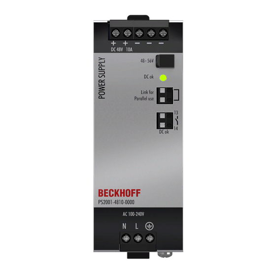
Technical data, mounting, wiring 3.12 Front side and operating elements Fig. 13: Front PS2001-4810-0000 Input terminals (screw terminals) Designation (A) Description Mains input N Mains input L PE input (protective conductor) Output terminals (screw terminals) Designation (B) Description two identical positive poles, positive output... -
Page 23: Emc
Tested with constant current loads, non-pulsating Switching frequencies PFC converter 100kHz fixed frequency Main converter 80kHz to 140kHz Output load dependent Auxiliary converter 60kHz fixed frequency PS2001-4810-0000 Version: 1.0... -
Page 24: Environment
2cm below the device. Tested in conjunction with DIN rails according to EN 60715 with a height of 15mm and a thickness of 1.3mm and standard mounting position. Fig. 14: Output current over ambient temperature; output current over installation altitude Version: 1.0 PS2001-4810-0000... -
Page 25: Protective Functions
At 230Vac, 50Hz, TN, TT / IT network Max. 0.16mA / 0.38mA At 110Vac, 50Hz, TN, TT / IT network Max. 0.23mA / 0.55mA At 132Vac, 60Hz, TN, TT / IT network Max. 0.39mA / 0.94mA At 264Vac, 50Hz, TN, TT / IT network PS2001-4810-0000 Version: 1.0... -
Page 26: Dielectric Strength
(column D). When performing the test, we recommend connecting the DC OK contact pins and the output contact pins. Type test 2500Vac 3000Vac 1000Vac 500Vac Component test 5s 2500Vac 2500Vac 500Vac 500Vac Field test 2000Vac 2000Vac 500Vac 500Vac Setting the cut-off current > 10mA > 10mA > 20mA > 1mA Version: 1.0 PS2001-4810-0000... -
Page 27: Declaration Of Conformity And Approvals
Class I Division 2 Groups A, B, C, D locations and for use in Group II Category 3 (Zone 2) environments Applicable for US and Canada Classification: ATEX: EPS 17 ATEX 1 089 X, II 3G EX ec nC IIC T4 Gc Classification: IECEx EPS 20.0047X PS2001-4810-0000 Version: 1.0... -
Page 28: Dimensions And Weight
Housing: Aluminum alloy Cover: Galvanized steel Ingress protection Small parts such as screws, nuts, etc. with a diameter greater than 5 mm Installation clearances See chapter on Safety instructions and installation requirements [} 9] Fig. 16: Front/side view PS2001-4810-0000 Version: 1.0 PS2001-4810-0000... -
Page 29: Application Notes
The capacitors are discharged during such an event, which leads to a voltage drop at the output. The following two examples show typical voltage drops for ohmic loads: Fig. 17: 20A peak current for 50ms, typ. (2x nominal current) Fig. 18: 50A peak current for 5ms, typ. (5x nominal current) PS2001-4810-0000 Version: 1.0... - Page 30 Peak current voltage drops Typically from 48V to 36V At 20A for 50ms, ohmic load Typically from 48V to 39V At 50A for 2ms, ohmic load Typically from 48V to 32V At 50A for 5ms, ohmic load Version: 1.0 PS2001-4810-0000...
-
Page 31: Output Circuit Breakers
20 m 25 m 39 m B-13A 13 m 17 m 28 m B-16A Don't forget to double the distance to the load (or the cable length) when calculating the total cable length (plus and minus cable). PS2001-4810-0000 Version: 1.0... -
Page 32: Charging Batteries
Parallel use to increase power PS2001-4810-0000 power supplies can be connected in parallel to increase the output power. The output voltage of all power supplies must be set to the same value (±100mV) in "Single Use" mode and with the same load conditions on all devices, or the factory settings of the devices can be retained. - Page 33 (terminals on the underside of the device), not in other installation positions or under other conditions that require a reduction in the output current (e.g. installation altitude ...). Remember that leakage current, electromagnetic interference, inrush current and harmonics increase when using multiple power supplies. Fig. 22: Parallel connection PS2001-4810-0000 Version: 1.0...
-
Page 34: Operation On Two Phases
Installation positions other than the input connections at the bottom and the output at the top require a reduction of the continuous output power or a limitation of the maximum permissible ambient temperature. The values for service life and MTBF given in this data sheet are only valid for the standard mounting orientation. Version: 1.0 PS2001-4810-0000... - Page 35 The following curves give an indication of permissible output currents for altitudes up to 2000m. Fig. 24: Mounting position A (standard mounting position) Fig. 25: Mounting position B (upside down) Fig. 26: Mounting position C (table mounting) Fig. 27: Mounting position D (horizontal clockwise) Fig. 28: Mounting position E (horizontal counterclockwise) PS2001-4810-0000 Version: 1.0...
-
Page 36: Appendix
This bracket is used to mount the devices to a wall or panel without using a DIN rail. The bracket can be mounted without loosening the DIN rail brackets. For more information please refer to the ZS5301-0003 documentation. Fig. 29: Isometric view, with example product PS2001-2405-0000 Fig. 30: Wall mounting: Front view, side view, hole pattern, with example product PS2001-2405-0000 Version: 1.0 PS2001-4810-0000... -
Page 37: Documentation Issue Status
Appendix Documentation issue status Version Comment - First public issue - Complements, corrections - Preliminary documentation for PS2001-4810-0000 PS2001-4810-0000 Version: 1.0... -
Page 38: Support And Service
Please contact your Beckhoff branch office or representative for local support and service on Beckhoff products! The addresses of Beckhoff's branch offices and representatives round the world can be found on her internet pages: https://www.beckhoff.com/english/beckhoff/world.htm You will also find further documentation for Beckhoff components there. - Page 40 More Information: www.beckhoff.com/ps2001-4810-0000 Beckhoff Automation GmbH & Co. KG Hülshorstweg 20 33415 Verl Germany Phone: +49 5246 9630 info@beckhoff.com www.beckhoff.com...
Need help?
Do you have a question about the PS2001-4810-0000 and is the answer not in the manual?
Questions and answers