Table of Contents
Advertisement
Quick Links
BREW CENTER, COFFEE BREWING EQUIPMENT
BC2, BC302
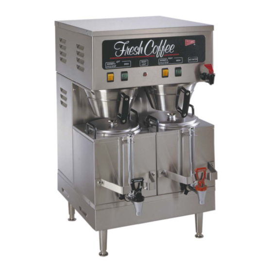
TWIN:
* Specifications
* Installation
Cecilware sells value... Worldwide
43 -05 20th Avenue, Long Island City, NY 11105
SINGLE:
BC-2E
BREWERS SHOWN WITH OPTIONAL STAINLESS STEEL FUNNEL
* Start up procedure
* Operating Instructions
BC1, BC301, BC120, BC240
MANUAL
* Adjustments
* Care Maintenance
TEL:
718-932-1414
FAX: 718-932-7860
BC-1E
* Parts Identification
* Wiring Diagram
N831A-C 4/3/2002
Advertisement
Table of Contents

Related Manuals for Cecilware BC1


Summary of Contents for Cecilware BC1
- Page 1 BREWERS SHOWN WITH OPTIONAL STAINLESS STEEL FUNNEL * Specifications * Start up procedure * Installation * Operating Instructions Cecilware sells value... Worldwide 43 -05 20th Avenue, Long Island City, NY 11105 BC1, BC301, BC120, BC240 SINGLE: BC-2E MANUAL * Adjustments * Care Maintenance TEL:...
-
Page 2: Electrical Specifications
SPECIFICATIONS ELECTRICAL SPECIFICATIONS MODEL NO. Volts Watts Amps Wall Outlet (Receptacle) Power Cord CE202 – 30A optional All Brew Centers are single phase with 3 wires plus a ground with cord and plug, except Eport 220V, 1 PH, (UROPEAN). MECHANICAL SPECIFICATIONS MODEL NO. - Page 3 Power Cord CE202 – Optional ? RECOMMENDED WIRING SIZES Model No. Single: BC1, BC301, BC120, BC240 Twin: BC2, BC302 Note: 1. Neutral (N) and Ground Wires to be 14 AWG Minimum.
-
Page 4: Initial Priming
24 cup and 36 cup brew cycles. Nevertheless, it is a good practice to check the output levels prior to brewing the first batch of coffee. BC1 and BC2: Full 36 cups (3 decanters) per brew cycle with a 20% by-pass. BC120 and BC240: Selectively 12 cups (1 decanter) or 24 cups (2 decanters) per brew cycle. -
Page 5: Adjustment Screw
ADJUSTMENTS 1. BY-PASS FLOW VALVE ADJUSTMENTS Depending on the model number, the BC Brewers have been factory set to brew 12, 24 and/or 36 cups of coffee, with the BY-PASS adjusted for a 20% BY-PASS flow of brewing water for the 36 cup, brew output only. -
Page 6: Thermostat Adjustment
2. TIMER ADJUSTMENT PROCEDURE Remove the top cover to access the brew timer(s). To INCREASE output: turn timer knob a small increment CLOCKWISE. To DECREASE output: turn timer knob a small increment COUNTER-CLOCKWISE. Check output level in carrier. BCI, BC2 Single Timer (L264A) 3. - Page 7 SPECIAL COMPONENTS TEST 1) CHECK DISPENSE VALVES FOR LIME BUILD-UP (Located inside top cabin) Drain the water tank to just below the level of the Dispense Valves. Remove the Valves and clean. You can take these valves apart by hand as shown. Replace the assembly as needed.
-
Page 8: Troubleshooting Guide
WARNING: To reduce the risk of electrical shock unplug the dispenser power cord before repairing or replacing any internal components of the unit.. Before any attempt to replace a component be sure to check all electrical connections for proper contact PROBLEM PROBABLE CAUSE a) Loose wire connection. -
Page 9: Cleaning And Sanitizing
CLEANING AND SANITIZING SANITIZING: All food dispensing units should be sanitized periodically. All parts to be sanitized must be cleaned first. To prepare a sanitizing solution: ADD 2 TSP. OF LIQUID CLOROX BLEACH (5.25% CONCENTRATION) TO 1 GALLON OF WATER AT ROOM TEMPERATURE (70°- 90°F). -
Page 10: Parts Identification
ITEM P/N P/N QTY SF26A SB49A 1 CABINET TOP COVER ---- SWITCH PANEL LABELS: N829A BC120 & BC240 N892A N815A BC1 / BC2 N822A N823A BC301 / BC302 5* L155A L155A BC2 ON-OFF SWITCH L155A L155A BC120 ON-OFF SWITCH L155A... - Page 11 TOP CABIN - PARTS IDENTIFICATION ITEM SPARE SINGLE UNITS TWIN UNITS PARTS L656A L656A L499A L499A M532A M523A G367A G367A G369A G369A G286A G286A K683A K683A M483A M483A L688A L688A L689A L689A L264A L264A 58026 L410A L410A B177A B177A SD06Q SD06Q K671Q K671Q...
- Page 12 BOTTOM CABIN OPEN VIEW BOTTOM CABIN - PARTS IDENTIFICATION SPARE BC301-IT PARTS ITEM L069A B083A CD257 C396A C395A CE202 CG99A [* RECOMMENDED SPARE PARTS] BC2-IT BC302-IT DESCRIPTION L069A 1 POWER SWITCH B083A 1 TERMINAL BLOCK CD257 1 WATER INLET VALVE C396A FUSE HOLDER C395A...
- Page 13 CARRIER ASS’Y CARRIER ASS’Y 97208 [* RECOMMENDED SPARE PARTS] Item Description Handle, black 3” Hold Down Bracket Thumb Screw Carrier Cover S.S. Gasket, Cover Carrier Label Screw Faucet Guard Faucet & Shank Ass’y 8” Faucet Washer Faucet Hex Nut Washer, Base Sight Gauge Shield Sight Gauge Glass Washer, End Cap...
- Page 14 BC-1E 120/240 3 WIRES + GROUND BREW CIRCUIT BREW VALVE FAUCET & SHANK ASS’Y 99461 BLACK WHITE C.G. 3100 WATTS 14A PROBE LOAD HI LIMIT FUSE 6 AMP. 1 PH 60Hz REFILL CIRCUIT C.G.
- Page 15 BC120E 2 WIRES+GRD 1800W 15A 1PH BC240E 2 WIRES+GRD 3120W 13A 1PH L2 S L1 SW2 SW3 I2 I1 WARMER BC-120E DUAL BREWTIME BC-240E DUAL BREWTIME BLACK WHITE C.G. BREW INDICATOR LIGHT PROBE LOAD FLOAT SWITCH HI LIMIT FUSE 6 AMP. C.G.
- Page 16 BC-301E 120/240 3 WIRES+GND 4140W 18A 1PH 60HZ BREW CIRCUIT REFILL CIRCUIT INLET VALVE PROBE 12 24 36 LOAD HI LIMIT BC-301E TRIPLE BREW TIME FUSE 6 AMP. BLACK WHITE C.G. C.G.
- Page 17 BC-2E 120/240 3 WIRE+GRD 6230W 26A 1PH 60HZ PROBE PROBE LOAD W R B BC-2E SINGLE BREW TIME HI LIMIT BLACK WHITE C.G. C.G.
- Page 18 PROBE LOAD HI LIMIT BLACK WHITE C.G. C.G.
Need help?
Do you have a question about the BC1 and is the answer not in the manual?
Questions and answers