Sam4s ER-390 Series Service Manual
Electronic cash register
Hide thumbs
Also See for ER-390 Series:
- Service manual (100 pages) ,
- Operation and program manual (206 pages)
Table of Contents
Advertisement
Quick Links
SERVICE
ELECTRONIC CASH REGISTER
All manuals and user guides at all-guides.com
ELECTRONIC CASH REGISTER
ER-390 SERIES
Manual
C O N T E N T S
1.
Precaution Statements
2.
Product Specifications
3.
Installation and Operation
4.
Disassembly and Assembly
5.
Maintenance and Adjustment
6.
Reference Information
7.
Special Circuit Descriptions
8.
Troubleshooting
9.
Exploded Views and Parts List
10. PCB Layout and Parts List
11. Block diagram
12. Wiring Diagram
13. Schematic Diagrams
Advertisement
Table of Contents

Related Manuals for Sam4s ER-390 Series


Summary of Contents for Sam4s ER-390 Series
- Page 1 All manuals and user guides at all-guides.com ELECTRONIC CASH REGISTER ER-390 SERIES SERVICE Manual ELECTRONIC CASH REGISTER C O N T E N T S Precaution Statements Product Specifications Installation and Operation Disassembly and Assembly Maintenance and Adjustment Reference Information...
- Page 2 All manuals and user guides at all-guides.com About this Manual This service manual describes how to perform hardware service maintenance for the SAM4S ER-390 Series Electronic Cash Register. Notes Notes may appear anywhere in the manual. They describe additional information about the item.
- Page 3 This manual may not, in whole or in part, be copied, photocopied, reproduced, translated or converted to any electronic or machine readable from without prior written permission of Shin Heung Precision . SAM4S ER-390 SERIES Service Manual First edition. June 2006. V1.0 Printed in KOREA...
- Page 4 All manuals and user guides at all-guides.com Overview of this ECR This ECR is a microprocessor-based system, using a 16 bits microprocessor. This service manual provides the technical information for many individual component systems, circuits and gives an analysis of the operations performed by the circuits. If you need more technical information, please contact our service branch or R&D center.
-
Page 5: Precaution Statements
Remplacer uniquement avec une batterie du même type recommended by the manufacturer. ou d’un type équivalent recommandé par le constructeur. Dispose used batteries according to the manufacturer’s Mettre au rebut les batteries usagées conformément aux instructions. instructions du fabricant. SAM4S ER-390 SERIES... -
Page 6: Servicing Precautions
5. Use only a grounded-tip soldering iron when soldering or unsoldering ESDs. 6. Use only an anti-static solder removal device. Many solder removal devices are not rated as anti-static; these can accumulate sufficient electrical charge to damage ESDs. SAM4S ER-390 SERIES... -
Page 7: Product Specifications
Power Consumption • Approx. 25W (Regularity) Power Requirement • AC 120V 60Hz, 230V 50Hz Environment • Temperature : 0℃ ~ 45℃ Condition • humidity : 30% ~ 80% RH Dimensions(mm) 400(W) x 450(D) x 266(H) Table2-1 General Specifications SAM4S ER-390 SERIES... -
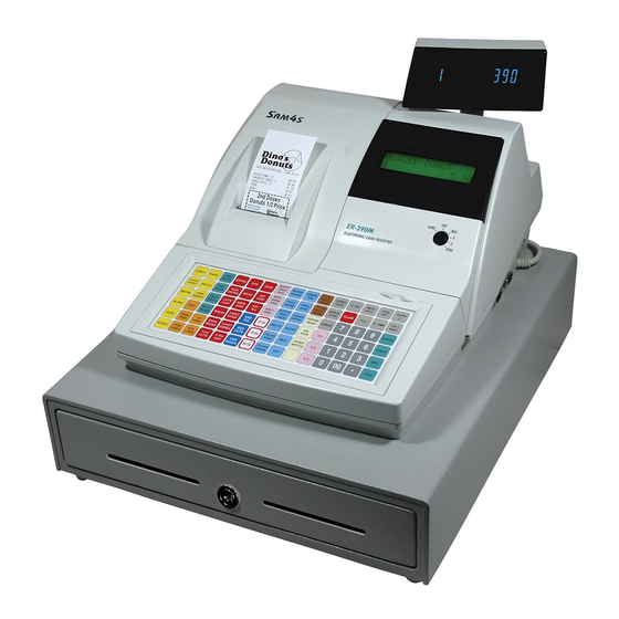
Page 8: Feature Locations
2-2-2 Feature Locations ① Printer Cover ② Key Board ③ Drawer ④ Customer 10-Digits VFD Display ⑤ Operator 16*2 Character LCD Display (ER-390M) Operator 10-Digits VFD Display(ER-390F) ⑥ Mode Key ⑦ RS-232 Serial I/F Connector Figure2-2 Location Features SAM4S ER-390 SERIES... -
Page 9: Printer Specification
• Reflecting Photo Sensor Paper-End Sensor • Micro Switch Printer Cover Open Sensor • 15,000,000 Lines Life Reliability • 37,000,000 Lines MCBF • 82.5 (W) ×147.3 (D) ×101.4 (H) Dimension (mm) • Approx. 365 g Weight Table2-2 Thermal Printer Specifications SAM4S ER-390 SERIES... -
Page 10: Paper Specification
• 12(W) × 24(H) Font (Including a horizontal) Character Structure • 1.25 mm(W) ×3.0 mm(H) Character Size • 1.5 mm Column Pitch • 3.75 mm (Including 6-dot line spacing) Line Pitch • 32 (12×24 Dots/Character) Number of Column Table2-4 Character Specification SAM4S ER-390 SERIES... -
Page 11: Other Component Specification
Temperature Character • -20℃ ~ 80℃ Operating Temperature • Reflecting Photo Sensor Type Paper End Sensor • SG-2BC (KODENSHI corp.) Spec • On when the printer head is load. Cover Open Sensor Detect Method Table2-5 Other Component Specifications SAM4S ER-390 SERIES... -
Page 12: Printer Connector
Phase A Phase A- Table2-7 Printer Line Feed (Paper Feed) Motor Pin Assignment Pin No. Signal Description Remark Paper End Sensor LED Current Limit Signal Paper End Sensor Input Signal Table2-8 Printer Paper End Sensor Pin Assignment SAM4S ER-390 SERIES... - Page 13 /LAT (nLATCH) STB1 (nSTROBE#1) Short on Print PCB STB2 (nSTROBE#2) STB3 (nSTROBE#3) (Thermistor) (Thermistor) (+5V) STB4 (nSTROBE#4) Short on Print PCB STB5 (nSTROBE#5) STB6 (nSTROBE#6) (Serial Clock) (Serial Data Input) (+8.5V) (+8.5V) Table2-9 Thermal Head Pin Assignment SAM4S ER-390 SERIES...
-
Page 14: Power Specification
• 7 Bit / 8 Bit Data Word Length • None / Even / Odd Parity • DB9P Female Connector For Bar Code Reader Voltage Supply • VCC(+5V/200mA) is supplied at 9Pin of D-SUB Connector. or other devices Table2-11 RS-232C Specification SAM4S ER-390 SERIES... - Page 15 2 Product Specifications 2-5 Interface Specifications 2-5-1-2 RS-232C I/F Cable Figure2-5 RS-232C Cable (9Pin to 25Pin) 2-5-1-3 Cable Connection & ) Figure2-6 RS232C Cable Connection (9Pin to 9Pin) & ) Figure2-7 RS232C Cable Connection (9Pin to 25Pin) SAM4S ER-390 SERIES...
- Page 16 Then the host recognizes that the ECR is busy. So, the host does not transmit a data to the ECR. If the ECR is released from busy, the ECR transmits XON(ASCII 11h) to host through the Serial Data Line. Then the host recognizes that the ECR is not busy. And the host transmits a data to the ECR. 2-10 SAM4S ER-390 SERIES...
-
Page 17: System Configuration
All manuals and user guides at all-guides.com 3 Installation and Operation 3-1 System Configuration 3-1-1 Configuration Figure 3-1 System Configuration SAM4S ER-390 SERIES... -
Page 18: Paper Roll Installation
Take-Up Spool and wind it onto the Spool two or three turns. 9. Place the Take-Up Spool into the Case-Lower behind the Printer above the roll paper. 10. If the paper is loose, rewind the Take-Up Spool to tighten the paper. Figure 3-2 Paper & Spool Installation SAM4S ER-390 SERIES... - Page 19 On Main PBA Ass’y MCR 1 EA Dealer Option Table 3-1 Option 3-2-5 Supplies Item Description Remark Paper Roll 1 EA Mode Key VD, REG, Z, P, C User Manual 1 EA Spool 1 EA Table 3-2 Supplies SAM4S ER-390 SERIES...
-
Page 20: Operation
Off, Register(REG), Manager(X), Clear Totals(Z) Void, Off, Register(REG), Manager(X), Clear Totals(Z), Program(PGM) Void, Off, Register(REG), Manager(X), Clear Totals(Z), Program(PGM), Service Mode(S) Table3-4 Key Function Note : The Key can be removed from the key lock in the OFF or REGISTER position. SAM4S ER-390 SERIES... - Page 21 All manuals and user guides at all-guides.com 3 Installation and Operation 3-3 Operation 3-3-2 Key Board Matrix (Dealer Option) Figure3-5 Key Board (STD) SAM4S ER-390 SERIES...
-
Page 22: Initial Clear
= = = = = = = = = = = = = = = = = = = = = = = RAM 1 OK RAM 2 OK RAM 3 NG ER-390M EPROM INFO.. VERSION : STD 1.0 CHECKSUM : 887C 2006 CLERK 00 No.000001 00000 Figure3-11 All Clear Key Sequence & Print Sheet SAM4S ER-390 SERIES... - Page 23 2. Press Press ‘2’, ‘4’ and ‘SBTL’ key on key board. 3. If error occurs, the message (232 NOGOOD) is displayed on VFD and the Buzzer beep. Then Press “Clear” key. Note : When the ports is unconnected the cable , the Error occur. SAM4S ER-390 SERIES...
- Page 24 All manuals and user guides at all-guides.com 3 Installation and Operation MEMO SAM4S ER-390 SERIES...
-
Page 25: Disassembly And Assembly
IPR-BRKT MODE S/W(B-3) and the MODE KEY ASS’Y(B-4). (Page9-3) 4. Remove the three screws(B-9) from the ASS'Y COVER MCR(B-1) and separate the COVER-SLOT(B-8) from the ASS'Y CASE UPPER(B). (Page9-3) 5. Remove two screws(B-6) from the COVER-SLOT(B-8) and separate the MCR(B-7) from the COVER-SLOT(B-8). (Page9-3) SAM4S ER-390 SERIES... - Page 26 3. Separate the three harnesses( , , ⓗ ⓙ ⓚ) and Remove the two screws(E-13). (page9-10) 4. Lift up the PBA SUB POWER SW(E-14) from the IPR-BRKT TRANS(E-21).(page9-10) 5. Remove the five screws(E-20:2PCS, E-22:3PCS) and Separate the IPR-BRKT TRANS(E-21) from the PMO-CASE LOWER(E-30).(page9-10) SAM4S ER-390 SERIES...
-
Page 27: Maintenance And Adjustment
Caution: Note that the thermal head(Thermal Element and Radiation Plate) becomes very hot during normal operation. To prevent the danger of burn injury from thermal, be sure to wait for about 10 minutes after turning power off before beginning the cleaning. SAM4S ER-390 SERIES... - Page 28 All manuals and user guides at all-guides.com 5 Maintenance and Adjustment MEMO SAM4S ER-390 SERIES...
-
Page 29: Reference Information
A10/P3.2 P8.1/TA4IN/U A9/P3.1 P8.2//INT0 P8.3//INT1 A8/P3.0 P8.4//INT2 P8.5/NMI A7/P2.7 A6/P2.6 A5/P2.5 A4/P2.4 XOUT A3/P2.3 /RESET A2/P2.2 P8.6/XCOUT A1/P2.1 P8.7/XCIN A0/P2.0 CNVSS /INT5/D15/P1.7 BYTE /INT4/D14/P1.6 P9.0/TB0IN/CLK3 /INT3/D13/P1.5 P9.1/TB1IN/RXD3/SCL3 D12/P1.4 P9.2/TB2IN/TXD3/SDA3 D11/P1.3 P9.3/DA0/TB3IN/CTS3 D10/P1.2 P9.4/DA1/TB4IN/CTS4 D9/P1.1 P9.5/ANEX0/CLK4 D8/P1.0 P9.6/ANEX1/TXD4/SDA4 SAM4S ER-390 SERIES... - Page 30 /WR (Write) AVSS Ground P4.7 /CS0 (Chip Select 0) P10.0 TPH_Thermister(R-Side) P4.6 /CS1 (Chip Select 1) VREF ADC Reference Voltage Input P4.5 /CS2 (Chip Select 2) AVCC +5V (VCC) P4.4 /CS3 (Chip Select 3) P9.7 VFD Display Latch SAM4S ER-390 SERIES...
- Page 31 I/O6 I/O2 I/O2 I/O5 I/O5 I/O3 I/O3 Data I/O4 I/O4 cont Pin Name Function Write Enable Input Chip Select Input Output Enable Input Control logic Address Inputs ~I/O Data Inputs/Outputs Power Ground Figure 6-2 SRAM K6T4008C2E Specification SAM4S ER-390 SERIES...
- Page 32 H = high level (steady state); L = low level (steady state); X = don’t care FUNCTION TABLE Figure 6-6 74HC138 FUNCTION TABLE Inputs Output Y Data Noninverting Inputs Outputs X = Don’t Care Z = High Impedance PIN 20 = V Output PIN 10 = GND Enables Figure 6-7 74HC541 SAM4S ER-390 SERIES...
- Page 33 Data Bus → Port C Data Bus → Control DISABLE FUNCTION Data Bus → Three-State Data Bus → Three-State Figure 6-9 82C55A Specification T1OUT MAX202E R1IN MAX232E R1OUT T1IN T2OUT T2IN R2IN R2OUT Figure 6-10 RS-232 Transceiver MAX232 SAM4S ER-390 SERIES...
- Page 34 SUPPLY CLOCK SERIAL SERIAL SERIAL-PARALLEL S HIFT REGISTER DATA I N DATA O UT LATCHES STROBE BLANKING BIPOLAR LOAD SUPPLY GROUND BLANKING BLNK STROBE D wg . FP -013-1 CLOCK GROUND Figure 6-12 VFD Driver UCN5812 Specification SAM4S ER-390 SERIES...
- Page 35 1. Emitter 2. Base 3. Collector [KSA1010-Y] [KSD288-Y] [KSA708-Y] [KSC945-G] SOT-23 SOT-23 SOT-23 1:A node 2:N.C 3:C athode 1:B ase 2:E mitter 3:C ollector 1:B ase 2:E mitter 3:C ollector [KSA1182-Y] [MMBT2222A] [MMBD6050] Figure 6-16 Transistor & Diode SAM4S ER-390 SERIES...
- Page 36 All manuals and user guides at all-guides.com 6 Reference Information MEMO SAM4S ER-390 SERIES...
-
Page 37: Special Circuit Descriptions
Cash Drawer Solenoid Driving / Fiscal Writing Voltage (+5VDC) Logic IC Driving / VFD Filament Voltage VPRT (+8.5VDC) Thermal Printer Step Motor. (+8.5VDC) Thermal Printer Head Driving Voltage (+3.6VDC Min) Battery Voltage Table 7-1 Power Source Voltage Descriptions SAM4S ER-390 SERIES... - Page 38 +8.5VDC Thermal Printer Head driving voltage is produced by VPH_ONOFF signal of CPU and the related Circuit(Q11,Q16,Q17) on Main PWB. The Source Voltage is VPRT (8.5V). 7-1-6 VBT : +3.6Vdc(Min) The Source Voltage is VCC(5V). When AC Power is off, VBT is supplied to SRAM, RTC for saving the data. SAM4S ER-390 SERIES...
-
Page 39: Reset Circuit
170Vac(Europe) . That is, when +24Vdc goes down to +14Vdc. The waveform of power fail signal refer to Figure 7-2 VDRV 100nF 6.8K 4.7K 4.7K U17:1 LM393D INT0_PFAIL 100nF 2.7K 3.3K 4.7K Figure 7-2 Power Fail Detect Circuit SAM4S ER-390 SERIES... -
Page 40: Battery Circuit
The Buzzer is used to inform several kinds of states which occur under system operating and gives some information to users by controlling the P8.0 pin of CPU. The frequency of buzzer is 2[KHz] VDRVVCC MMBD6050LT1 BUZZER MMBT2222A 4.7K BUZZER Figure 7-5 Buzzer Circuit SAM4S ER-390 SERIES... - Page 41 Display data to the driver repeatedly having given time interval in series and then Fluorescent Display is operated. CLK, DATA, LATCH STROBE 0 1 2 3 4 5 6 7 8 9 DRIVER 10Digits UCN5812 +30V,+5V,GND Front & Rear VFD PBA Figure 7-7 VFD Diagram SAM4S ER-390 SERIES...
-
Page 42: Keyboard Circuit
DATA[0:7] ADDRESS DECODER(74HC138) (U21,U24 ) DIODE( MMBD6050L *12) Pull-Up • • 74HCT541 • (U23) 90 KEYS • • • • • • • COMMON PORT • • • • • MODE KEY Figure 7-8 Keyboard Block Diagram SAM4S ER-390 SERIES... - Page 43 257 ~ 320 (192 Dots) STB6 321 ~ 384 Table 7-2 Printer Head Strobe Processing Printer Line TPH_STB1 Strobe Circuit M30800SFP TPH_STB2 TPH_LATCH Latch Register TPH_DATA Shift Register TPH_CLK THERMAL PRINTER Figure 7-9 Thermal Printer Block Diagram SAM4S ER-390 SERIES...
- Page 44 All manuals and user guides at all-guides.com 7 Special Circuit Descriptions 7-5 Thermal Printer Circuit DATA 384 Bits 384 Bits 384 Bits LATCH Printing(1~192) STB1,2,3 Printing(193~384) STB4,5,6 Figure 7-10 Thermal Printer Timing Waveform SAM4S ER-390 SERIES...
-
Page 45: Troubleshooting
1. Check the CPU P8.7 2. Check the Capacitor(C50) (VPH_ONOFF) Port 3. Check the VCC whether 2. Check the KSA1010,MMBT2222 it is short or open. (Q11,Q16,Q17) on Main Board. 3. Check the VDRV signal whether it is short. SAM4S ER-390 SERIES... -
Page 46: System Problem
4. Replace the SRAM. 1. Check the nCS, nRD, nWR signal of RTC 2. Check the VBT(Battery Volt.). RTC Ok? 3. Check the Decoder IC 74HC138 (U11). 4. Check the RTC Clock 32.768KHz 5. Replace the RTC(RS5C372A) SAM4S ER-390 SERIES... - Page 47 3. Check the LATCH Signal (CPU P9.7) 4. Check the Harness. 1. Check and Replace the VFD PBA. VFD PBA 2. Check the UCL5812. Assy Ok? 3. Check the VFD. 4. Check the Harness & Soldering Point. SAM4S ER-390 SERIES...
- Page 48 2. Check the related Circuit and Pattern. 3. Check the Harness. 4. Check the Thermister of TPH. 1. Check the Control Signal on CPU (Data/CLK/Latch/Strobe1,2,3,4) Print 2. Check the Harness. 3. Check the related Circuit and Pattern. SAM4S ER-390 SERIES...
-
Page 49: Key Board Problem
2. Check the Matrix Bus & Data Bus Failure? 3. Check the Diodes(D20~D27) 4. Check the Key Board Assy 1. Check the Harness & Mode Key Assy Mode Key 2. Check Diode (D12) 3. Check the 74HCT541 & Data Bus & CPU P10.3 SAM4S ER-390 SERIES... - Page 50 Compulsory 2. Check the Micro switch in the Drawer. Failure? Spool Motor Problem 1. Check the Spool Motor Signal CPU P1.4 Spool Motor 2. Check the Harness 3. Check the related Circuit and Pattern on Main Board. SAM4S ER-390 SERIES...
-
Page 51: Rs-232C Serial Communication Problem
3. Check whether Signal is affected by the Cable Noise. 1. Check the connection of the H/W handshaking Line and Other side. H/W Handshake 2. Check the I/F Cable whether it is open or short. 3. Confirm the H/W handshaking Protocol. SAM4S ER-390 SERIES... - Page 52 All manuals and user guides at all-guides.com 8 Troubleshooting MEMO SAM4S ER-390 SERIES...
-
Page 53: Exploded Views And Parts List
All manuals and user guides at all-guides.com 9 Exploded Views and Parts List 9-1 Exploded View Figure9-1 Total Disassembly SAM4S ER-390 SERIES... -
Page 54: Parts List
All manuals and user guides at all-guides.com 9 Exploded Views and Parts List 9-2 Parts List Figure9-2 ASS’Y COVER-PRINTER A. ASS’Y COVER-PRINTER Parts No. Description / Specification Q`ty Design-Location Serviceable Remark JK97-20009A MEA-COVER PRINTER JK72-20062A PMO-COVER PRINTER SAM4S JK70-10320A IPR-CUTTER PAPER SAM4S ER-390 SERIES... - Page 55 All manuals and user guides at all-guides.com 9 Exploded Views and Parts List 9-2 Parts List Figure9-3 ASS’Y CASE-UPPER SAM4S ER-390 SERIES...
- Page 56 SCREW-TAPPING B-22 JK07-00007A LCD:16CHAR*2LINE B-23 JK72-20110A PMO-HOLDER DISPLAY B-24 6002-000175 SCREW-TAPPING B-25 JK59-30027A UNIT-KEYBOARD B-26 6002-000174 SCREW-TAPPING B-27 6002-000172 SCREW-TAPPING JK68-40062B LABEL(P)-KBD SHEET MIRA JK68-40062C LABEL(P)-KBD SHEET B-28 JK68-40062D LABEL(P)-KBD SHEET JK68-40062E LABEL(P)-KBD SHEET JK68-40062F LABEL(P)-KBD SHEET SAM4S ER-390 SERIES...
- Page 57 All manuals and user guides at all-guides.com 9 Exploded Views and Parts List 9-2 Parts List Figure9-4 Printer (STM-210) SAM4S ER-390 SERIES...
- Page 58 All manuals and user guides at all-guides.com 9 Exploded Views and Parts List 9-2 Parts List Figure9-5 Lubrication Points of the Printer (STM-210) SAM4S ER-390 SERIES...
- Page 59 SCREW-MACHINE C-37 JK72-20002A PMO-PAPER SUPPLY C-38 JK92-01224A PBA-SUB PRT CONN BOARD C-39 6002-000175 SCREW-TAPPING C-40 JK39-00012A CBF-HARNESS-KEY OPTION C-41 JK72-20009A PMO-COVER FRONT C-42 6002-000147 SCREW TAPPING C-43 6003-000198 SCREW TAPPING C-44 JK72-20114A PMO-SEPARATOR C-45 JK39-40021A CBF HARNESS SAM4S ER-390 SERIES...
- Page 60 2. Open the COVER TOP. disassemble it from the PRINTER. 3. Disassemble the TPH assembly by pulling the 4. Assemble the TPH assembly in reverse order and lower part of TPH assembly and lift it up. close the COVER TOP. SAM4S ER-390 SERIES...
- Page 61 9 Exploded Views and Parts List 9-2 Parts List Figure9-6 ASS’Y KEYBOARD D. ASS’Y KEYBOARD Parts No. Description / Specification Q`ty Design-Location Serviceable Remark JK59-30027A UNIT-KEYBOARD JK81-20049A FRAME:90 KEY JK81-20049B KEY-RUBBER:90 KEY JK81-20049C FPC-ASSY:90 KEY JK81-20049D BASE-PLATE:90 KEY JK81-20049E SCREW-TAPPING:M2.6X8 SAM4S ER-390 SERIES...
- Page 62 All manuals and user guides at all-guides.com 9 Exploded Views and Parts List 9-2 Parts List Figure9-7 ASS’Y CASE-LOWER 9-10 SAM4S ER-390 SERIES...
- Page 63 E-28 JK92-00983A PBA MAIN-1M,FISICAL: 1M BYTE FISCAL E-29 JK72-40205A PMO-CASE FISICAL BOARD FISCAL JK72-20182A PMO-CASE LOWER:S1(TEAR OFF) JK72-20182B PMO-CASE LOWER:S1,POWER JK72-20182C PMO-CASE LOWER:S2,POWER E-30 JK72-20182D PMO-CASE LOWER:S3,POWER JK72-20182E PMO-CASE LOWER:POWER JK72-20182F PMO-CASE LOWER:NON E-31 JK39-40603A HARNESS-DRA/COMP SAM4S ER-390 SERIES 9-11...
- Page 64 BILL-COIN (5B5C) c. ASS'Y HOUSING d. ASS'Y LOCK b. ASS'Y TRAY-TILL e. ASS'Y BOTTOM Figure9-9 Drawer (5B/5C) a. ASS'Y BILL-COIN (7B8C) c. ASS'Y HOUSING d. ASS'Y LOCK b. ASS'Y TRAY-TILL e. ASS'Y BOTTOM Figure9-10 Drawer (7B/8C) 9-12 SAM4S ER-390 SERIES...
- Page 65 IPR-PLATE FRONT JK70-10014B IPR-PLATE FRONT JK75-00025A MEA-TRAY TILL: 4B8C,7B8C JK75-00025B MEA-TRAY TILL: 5B5C JK73-10203A RPR-TENSION JK75-10386A MEC-ROLLER 6031-000549 WASHER-PLAIN 6003-000221 SCREW-TAPTITE JK70-10324A IPR-SUPPORT TRAY JK70-40302A ICT,SHAFT PIN b-10 6044-000124 RING-E b-11 6002-001042 SCREW-TAPPING b-12 JK70-10323A IPR-PLATE CLIP SAM4S ER-390 SERIES 9-13...
- Page 66 Description / Specification Q`ty Design-Location Serviceable Remark JK97-01976A MEA-UNIT BOTTOM JK97-01076B MEA-UNIT BOTTOM: UNIVERSAL JK70-10938A IPR-PLATE BOTTOM JK73-40200A RMO-STOPPER JK73-10902A RMO-STOPPER: UNIVERSAL JK61-40200A RMO-FOOT RUBBER 6002-000234 SCREW-TAPPING 6003-000267 SCREW-TAPTITE 6003-000267 SCREW-TAPTITE JK70-10401A IPR-PLATE SPRING 6003-000267 SCREW-TAPTITE 9-14 SAM4S ER-390 SERIES...
-
Page 67: Main Pcb Layout
All manuals and user guides at all-guides.com 10 PCB Layout and Parts List 10-1 Main PCB Layout 10-1-1 MAIN PCB (PCB: JK41-10552C) 10-1-1-1 Component Side View SAM4S ER-390 SERIES 10-1... - Page 68 CRYSTAL-UNIT:0.032768MHz,20ppm,28-AAY,12 3002-001027 BUZZER-PIEZO:85dB,1.5V,24mA,2.048KHz,BK 3301-000344 CORE-FERRITE BEAD:AA,-,3.5x0.6x6.5mm,-,- 3601-000261 FUSE-CARTRIDGE:250V,3.15A,TIME-LAG,GLASS 3602-000001 FUSE-CLIP:-,-,30mohm 3704-000255 SOCKET-IC:32P,DIP,SN,2.54mm U15,U19 3708-000147 CONNECTOR-FFC:12P,1R,2.54mm,ST,BLACK CN13 3708-000327 CONNECTOR-FFC:8P,1R,2.54mm,ST,BLACK CN14 3711-000242 CONNECTOR-HEADER:1WALL,4P,1R,3.96mm,STRA 3711-000840 CONNECTOR-HEADER:BOX,30P,2R,2MM,STRAIGHT CN8,CN9 3711-001475 CONNECTOR-HEADER:NOWALL,3P,1R,2.54mm,STR CN15 3710-000111 CONNECTOR-SHUNT:2P,1R,2.54mm,-,AUF CN15 3711-002002 CONNECTOR-HEADER:-,22P,2R,2mm,STRAIGHT,S 3711-004102 WAFER;BOX-HEADER,1R,2P,2.5mm,STRAIGHT,BL 3711-004105 WAFER;BOX-HEADER,1R,4P,2.5mm,STRAIGHT 10-2 SAM4S ER-390 SERIES...
- Page 69 IC-SRAM:681000,128Kx8BIT,SOP,32P,525MI U16,U20 1202-000164 IC-VOLTAGE COMP.:393,SOP,8P,150MIL,DUAL, 1203-000404 IC-DC/DC CONVERTER:34063,SOP,8P,150MIL,P 1205-001771 IC-CLOCK GENERATOR:FS781BZB,SOP,8PIN R10,R48,R108,R109,R110 2007-000026 R-CHIP:200OHM,5%,1/10W,DA,TP,2012 R111,R112,R113,R118,R119 R130,R131,R132,R133,R134 2007-000028 R-CHIP:39OHM,5%,1/10W,DA,TP,2012 R64,R71,R100 2007-000030 R-CHIP:560OHM,5%,1/10W,DA,TP,2012 R37,R42,R43,R44,R47,R50 2007-000290 R-CHIP:100OHM,5%,1/10W,DA,TP,2012 R55,R57,R61,R68,R70,R86 R87,R88,R90 R1,R2,R5,R6,R9,R11,R13 R25,R27,R29,R30,R33,R40 R45,R46,R54,R56,R60,R62 2007-000300 R-CHIP:10KOHM,5%,1/10W,DA,TP,2012 R63,R66,R67,R72,R74,R76 R78,R81,R85,R92,R93,R102 R124,R125,R135 2007-000355 R-CHIP:12KOHM,5%,1/10W,DA,TP,2012 SAM4S ER-390 SERIES 10-3...
- Page 70 2203-000239 C-CERAMIC,CHIP:0.1nF,5%,50V,NP0,TP,2012 C71,C81,C95,C96,C97,C98 C99,C100,C101,C102,C104, C105,C106,C107 2203-000260 C-CERAMIC,CHIP:10nF,10%,50V,X7R,TP,2012 C74,C79,C61 2203-000595 C-CERAMIC,CHIP:0.22nF,5%,50V,NP0,TP,2012 2203-000634 C-CERAMIC,CHIP:0.022nF,5%,50V,NP0,TP,201 C51,C52 C3,C6,C10,C13,C15,C18,C19 2203-000938 C-CERAMIC,CHIP:0.47nF,5%,50V,NP0,TP,2012 C20,C21,C22,C24,C29 C9,C12,C14,C16,C17,C23 2203-000990 C-CERAMIC,CHIP:1uF,+80-20%,25V,Y5V,TP,20 C26,C27,C30,C31,C33,C34 C35,C36,C37 2801-003382 CRYSTAL-SMD:14.7456MHZ,SX-1,18pF L1,L2,L3,L4,L7,L8,L9,L10,L11 3301-000317 CORE-FERRITE BEAD:AB,2x1.25x0.9mm,-,- L12,L13,L14,L15,L16,L17,L18 L19,L20,L21,L22 JK41-10552B PCB-MAIN:ER-390MF,FR-4,2L,T1.6,RoHS ER-430F(FISCAL) JK41-10552C PCB-MAIN:ER-390M,MCR,FR-4,2L,T1.6,RoHS ER-430M 10-4 SAM4S ER-390 SERIES...
-
Page 71: Component Side
Design Location Serviceable Remarks JK92-01224A PBA SUB-PRT CONN BOARD:STM-210,ER-650R ASSY 3708-001390 CONNECTOR-FPC/FFC/PIC:21P,2.54MM,STRAIGH 3711-000961 CONNECTOR-HEADER:BOX,4P,1R,2.5mm,STRAIGH 3711-003969 CONNECTOR-HEADER:BOX,2P,1R,2.5mm,STRAIGH 3711-003409 CONNECTOR-HEADER:BOX,3P,1R,2mm,STRAIGHT, 3711-004059 CONNECTOR-HEADER:BOX,30P,2R,2mm,ANGLE,SN 3711-000965 CONNECTOR-HEADER:BOX,4P,1R,2.5mm,ANGLE 3711-003968 CONNECTOR-HEADER:BOX,3P,1R,2.5mm,STRAIGH 0501-000399 TR-SMALL SIGNAL:KSC945-G,NPN,250mW,TO-92 2001-000395 R-CARBON:180KOHM,5%,1/4W,AA,TP,2.4X6.4MM 2001-000062 R-CARBON:470OHM,5%,1/4W,AA,TP,2.4X6.0MM 2401-000131 C-AL:1000uF,20%,16V,GP,TP,10x20,5 JK41-10542A PCB-PRT CONN:STM-210,FR-4,2L,T1.6mm,57 SAM4S ER-390 SERIES 10-5... -
Page 72: Component Side View
10 PCB Layout and Parts List 10-3 Power Switch PCB Layout 10-3-1 Component Side View 10-3-2 Parts List Part-No Description / Specification Q’TY Design Location Serviceable Remarks JK92-01227B PBA SUB-POWER SW:ER-5200/5500,STD ASSY 3711-000190 CONNECTOR-HEADER:1WALL,2P,1R,7.92mm,ST 3711-000829 CONNECTOR-HEADER:BOX,2P,1R,6.2mm,ST CN1,CN2 JK41-10545B PCB-POWER SWITCH:ER-52/5500,FR-1,1L,T1.6 10-6 SAM4S ER-390 SERIES... -
Page 73: Display Layout
Design Location Serviceable Remarks JK92-01242A PBA SUB-380,DISPLAY:FUTABA,10G ASS’Y 3711-004111 WAFER;BOX-HEADER,1R,8P,2.5mm,ANGLE 3711-002002 CONNECTOR-HEADER:-,22P,2R,2mm,STRAIGHT,S JK07-00005A DISPLAY VFD-DC10G:FUTABA,10-LT-50GK JK39-40600A HARNESS-DISPLAY;ER380,UL1007#26,350 ㎜,8P CORE/350mm JK73-10207A RPR-PAD:ER-220N,SPONGE,-,BLK,- T5.0 1003-001381 IC-VFD:HV5812P,DIP,28P,540MIL,-,-,ST,PLA 0402-000208 DIODE-RECTIFIER:EK-04,40V,1.5A,DO-41 0402-000129 DIODE-RECTIFIER:1N4003,200V,1A,DO-41,TP JC39-40511A CBF HARNESS:ML-80,JUMPER,AWG22,52mm,SILV J1 ~ J21 JK41-10005B PCB-DISPLAY(10G):ER-350/F,FR-1,1L,T1.6,F SAM4S ER-390 SERIES 10-7... - Page 74 Remarks JK92-00970B PBA SUB-TURRET:ER-450,WORLD,BASIC 3711-004109 WAFER;BOX-HEADER,1R,8P,2.5mm,STRAIGHT WHITE JK07-00005A DISPLAY VFD-DC10G:FUTABA,10-LT-50GK JK39-40606A HARNESS-TURRET:ER-450,8P,500mm,TUBE TURR TO MAIN TUBE JK73-10207A RPR-PAD:ER-220N,SPONGE,-,BLK,- T5.0 1003-001381 IC-VFD:HV5812P,DIP,28P,540MIL,-,-,ST,PLA 0402-000129 DIODE-RECTIFIER:1N4003,200V,1A,DO-41,TP 0402-000208 DIODE-RECTIFIER:EK-04,40V,1.5A,DO-41 2202-000630 C-CERAMIC,MLC-AXIAL:100nF,10%,50V,X7R,TP C1,C2 JC39-40511A CBF HARNESS:ML-80,JUMPER,AWG22,52mm,SILV J1 ~ J9 JK41-10547A PCB-TURRET:ER-650/5200,FR-1,1L,T1.6 10-8 SAM4S ER-390 SERIES...
- Page 75 PBA SUB-FISCAL:ER-420F,1M ASS’Y 1102-000109 IC-EPROM:27C010,128Kx8BIT,DIP,32P,600MI 0403-000525 DIODE-ZENER:1N4733A,5.1V,5%,1W,DO-41 JK39-40640A HARNESS-FISCAL:ER-450,30P,130mm,2mm 0404-001051 DIODE-SCHOTTKY:SK14,40V,1000MA,DO-214AA, D1,D2 0501-000457 TR-SMALL SIGNAL:MMBT2222A,NPN,350MW,SOT- 2008-000027 R-CHIP:1.2KOHM,5%,1/10W,1608 R9,R10,R12 2008-000037 R-CHIP:4.7KOHM,5%,1/10W,1608 R1,R2,R3,R4,R5 2008-000037 R-CHIP:4.7KOHM,5%,1/10W,1608 R6,R7,R8,R11,R13 2008-000044 R-CHIP:10KOHM,5%,1/10W,1608 2204-000010 C-CERAMIC,CHIP:100pF,5%,50V,1608 C1,C2,C3,C4,C5 2204-000010 C-CERAMIC,CHIP:100pF,5%,50V,1608 C6,C7,C8 2204-000028 C-CERAMIC,CHIP:100nF,+80-20%,25V,Y5V,160 JK41-10570A PCB-FISCAL:GREECE,2M,FR-4,2L,T1.6mm SAM4S ER-390 SERIES 10-9...
-
Page 76: Interface Layout
C1,C2,C3,C4,C5 2204-000010 C-CERAMIC,CHIP:100pF,5%,50V,1608 C6,C7,C8 2204-000028 C-CERAMIC,CHIP:100nF,+80-20%,25V,Y5V,160 JK41-10570A PCB-FISCAL:GREECE,2M,FR-4,2L,T1.6mm 10-6 Interface Layout 10-6-1 Exploded View 10-6-2 Parts List Part-No Description / Specification Q’TY Design Location Serviceable Remarks JK92-01280A PBA SUB-I/F:ER-380/M,232*2 3711-002002 CONNECTOR-HEADER:-,22P,2R,2mm,STRAIGHT,S 3701-000232 CONNECTOR-DSUB:9P,2R,FEMALE,ANGLE,AUF CN3,CN4 JK41-10571A PCB-I/F:ER-380/M,232*2,FR-4,2L,T1.6mm 10-10 SAM4S ER-390 SERIES... -
Page 77: Block Diagram
74HC138 FA16,17 nCS_EPROM nCS2 CS_KEYSCAN FISICAL VOLT FISICAL I/F KEY & MODE BUFFER DRIVE 82C55 SCAN RETURN 74HC541 12.5V 6.2V ( 0:15 ) ( 0:7 ) SCAN RETURN KEY BOARD FISICAL MEMORY B’D MODE KEY 512K/1M/2M SAM4S ER-390 SERIES 11-1... - Page 78 74HC138 FA16,17 nCS_EPROM nCS2 CS_KEYSCAN FISICAL VOLT FISICAL I/F KEY & MODE BUFFER DRIVE 82C55 SCAN RETURN 74HC541 12.5V 6.2V ( 0:15 ) ( 0:7 ) SCAN RETURN KEY BOARD FISICAL MEMORY B’D MODE KEY 512K/1M/2M 11-2 SAM4S ER-390 SERIES...
-
Page 79: Wiring Diagram
All manuals and user guides at all-guides.com 12 Wiring Diagram 12-1 Wiring Pin Connection MAIN PBA CN12 CN13 CN14 SAM4S ER-390 SERIES 12-1... - Page 80 TXD1/CLK VPH (+8.5V) RXD1/DATA VPH (+8.5V) MOT_LF_B- FA10 CN13 / 14= Keyboard ACUT SENS IN(Only Receipt) MOT_LF_B+ FA11 CN4= RS-232 / CN6=LCD DISPLAY MOT_ACUT1(Only Receipt) MOT_LF_A+ CN1 = SPOOL MOT_ACUT2(Only Receipt) MOT_LF_A- CN12 = MODE KEY 12-2 SAM4S ER-390 SERIES...
- Page 81 1) VFD Front Schematics(ER-390F) ----------------------------- 13-13 2) VFD Rear Schematics(ER-390F) ------------------------------ 13-14 3) VFD Rear Schematics(ER-390M) ------------------------------ 13-15 4. Fiscal PCB Schematics. ------------------------------------------- 13-16 5. STM-210 Printer PCB Schematics. ----------------------------- 13-17 6. Interface PCB Schematics. --------------------------------------- 13-18 SAM4S ER-390 SERIES 13-1...
- Page 82 All manuals and user guides at all-guides.com 13-2 SAM4S ER-390 SERIES...
- Page 83 All manuals and user guides at all-guides.com SAM4S ER-390 SERIES 13-3...
- Page 84 All manuals and user guides at all-guides.com KM684000LP-7 KM681000LG-7 KM681000LG-7 74HC138 M27C040 13-4 SAM4S ER-390 SERIES...
- Page 85 All manuals and user guides at all-guides.com SAM4S ER-390 SERIES 13-5...
- Page 86 All manuals and user guides at all-guides.com 74HC245 100nF 100pF 100pF 100pF 100pF KSA1182-Y KSA1182-Y 13-6 SAM4S ER-390 SERIES...
- Page 87 All manuals and user guides at all-guides.com 470pF 470pF 470pF 470pF 470pF 470pF 470pF 470pF 470pF 470pF 470pF 470pF SAM4S ER-390 SERIES 13-7...
- Page 88 R117 4.7K R126 4.7K R127 4.7K R128 4.7K R129 4.7K R122 4.7K R116 4.7K 74HCT541 100pF C102 100pF C101 100pF C100 100pF 100pF 100pF C107 100pF 100pF C106 100pF 100pF C105 100pF 100pF C104 74HC138 74HC138 13-8 SAM4S ER-390 SERIES...
- Page 89 All manuals and user guides at all-guides.com 150K 100pF 100pF 100pF 100pF SAM4S ER-390 SERIES 13-9...
- Page 90 All manuals and user guides at all-guides.com 13-10 SAM4S ER-390 SERIES...
- Page 91 All manuals and user guides at all-guides.com SAM4S ER-390 SERIES 13-11...
- Page 92 All manuals and user guides at all-guides.com 13-12 SAM4S ER-390 SERIES...
- Page 93 All manuals and user guides at all-guides.com P10_H P8_DP P7_D P6_E P5_C P4_G P3_F P2_B P1_A SAM4S ER-390 SERIES 13-13...
- Page 94 CN2:G CN2:F CN2:E CN2:D CN2:C CN2:B P4_G BLUE CN2:A P3_F CN1:K P8_DP CN1:J P7_D SEN_DISPDISCON CN1:I P6_E P7_D CN1:H P5_C P8_DP CN1:G CN1:F P4_G P5_C CN1:E P3_F P2_B CN1:D P2_B P1_A P1_A CN1:C P6_E CN1:B CN1:A 13-14 SAM4S ER-390 SERIES...
- Page 95 All manuals and user guides at all-guides.com P10_H P8_DP P7_D P6_E P5_C P4_G P3_F P2_B P1_A SAM4S ER-390 SERIES 13-15...
- Page 96 All manuals and user guides at all-guides.com 4.7K 100pF 4.7K 100pF 4.7K 100pF 4.7K 100pF 4.7K 100pF 4.7K 100pF 4.7K 100pF 4.7K 100pF EPROM 13-16 SAM4S ER-390 SERIES...
- Page 97 All manuals and user guides at all-guides.com FPC CABLE SAM4S ER-390 SERIES 13-17...
- Page 98 All manuals and user guides at all-guides.com 13-18 SAM4S ER-390 SERIES...
-
Page 99: Update Log
Use this page to record any special servicing information such as Service Bulletins or Supplements. When possible, record changes to Code numbers directly on the actual Parts List. Always record Service Bulletin numbers and Application Dates on this log to ensure that your data is always as current as possible. SAM4S ER-390 SERIES... - Page 100 All manuals and user guides at all-guides.com ⓒ Shin Heung Precision. June 2006 Printed in KOREA V1.0 Code No. : JK68-70112A...
Need help?
Do you have a question about the ER-390 Series and is the answer not in the manual?
Questions and answers