Table of Contents
Advertisement
Quick Links
INSTRUCTIONS FOR MODELS
S-1496-LH
S-1498-LH
For additional assistance or service please contact:
SPEAKMAN
®
800-537-2107
customerservice@speakman.com
www.speakman.com
92-S-1496-LH-98-05
2
Apply Thread Seal Tape to both ends of Shower Arm Gooseneck, and Bottom Plug. Thread Shower Arm Gooseneck into Valve
Body being sure to properly align outlet. Install Plug into bottom port of Valve Body and Wrench tighten.
4
Mounting location of Shower Valve.
Determine mounting location of Shower Valve. (See
Rough-In Diagram located at the end of this document).
Secure with Mounting Screws (not included) to structure
capable of supporting the product in use.
Ensure there is adequate distance between the Valve
and mounting structure to allow for installation of Water
Supply lines.
Note: A Spacer Block with a thickness of 1/2"-9/16"
is required between the Shower Valve (1) and the
Mounting Structure (2) only. This is to allow for adequate
clearance while installing inlet supply lines.
TOOLS AND SUPPLIES
Phillips
Flat Tip
Adjustable
Screwdriver
Screwdriver
Wrench
Thread Seal
Measuring
Tape
Tape
Pencil
3/32" Hex Key Wrench
(Included)
HELPFUL TOOLS & SUPPLIES:
Safety
Level
Glasses
IMPORTANT
• Be sure to read instructions thoroughly before
beginning installation.
• Be sure to have properly adjusted the Temperature
Limiting Stop (TLS) as outlined in this Installation
Manual.
• Inspect all connections after installation of valve.
• This valve has an operating range of
20-80 Psi.
• This valve is designed to be used in conjunction
a shower head rated at
1.75 gpm (6.6 L/min)
higher flow rate.
• NOTE: This installation manual covers several
models of valves. While the appearance of your
valve may differ from those shown, the installation
method is the same.
•
Maximum water pressure: 125 psi static; minimum
water pressure: 20 psi flowing; minimum cold
supply temperature: 40 °F; maximum hot supply
temperature: 160 °F.
SAFETY TIPS
Cover your drain to prevent loss of parts. Be sure to wear
eye protection while cutting pipe.
MAINTENANCE
Your new Shower/Bath Valve is designed for years of
trouble-free performance. Keep it looking new by cleaning
it periodically with a soft cloth. The use of harsh chemicals
and abrasives on any of the Speakman custom finish
products may damage the finish and void the product
warranty. Please be sure to only use approved cleaners.
Please contact Speakman for any clarification of
acceptable cleaners.
This type of valve must be cleaned and maintained on a
regular basis. Periodic maintenance should be performed
at least every 12 months or after any changes have been
made to the building's plumbing system. Valves that are
installed outdoors should be winterized by removing all of
the internal parts and removing any standing water from
the valve. Quarterly the maximum hot temperature setting
(TLS) should be checked and adjusted accordingly.
WARRANTY
Warranty information can be found at:
www.speakman.com
3
HANDLE AND DIAL CAP REMOVAL
The Handle and Dial Cap must be removed for proper mounting of the Shower Valve and to adjust the Temperature Limit Stop.
Remove the Handle Screw (1), then slide the Handle (2) off. Remove the Dial Cap Screw (3) followed by sliding off the Dial
Cap (4).
3/32"
5
Apply Thread Seal Tape to HOT and COLD Pipe
Connections (not supplied). Install the HOT and COLD
Pipe Connections to the Valve accordingly, either
through the wall, from the ceiling, or from the floor. For
ceiling and floor mounts, hold 1" from finished wall to
center of supply lines. Thread
into Valve Body and Wrench tighten.
Turn on water
supply and check for leaks.
NOTE:
Illustration shown is for reference only.
FREEZE PROTECTION
• Mounting location must be capable of supporting the
product in use.
Freeze damage to the shower unit will void the
warranty. It is important to winterize the complete
shower unit. The unit must be drained of all water
in freezing conditions. This includes removing the
valve cartridge and the shower head from the unit.
Store the valve cartridge and shower head indoors.
CAUTION: When outdoor temperature
with
rises above 90 degrees, use caution to
or
prevent scalding from water stored within
the unit. It is recommended to flush the unit
by turning it on for 30 seconds before
entering the shower water. This will avoid
accidental scalding by the user and ensure
safe use of the shower unit.
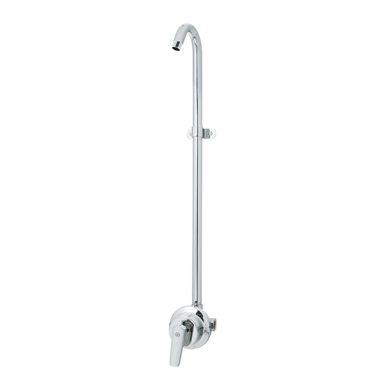
1
Slide the Strap (1) onto the Shower Arm (2).
Advertisement
Table of Contents

Subscribe to Our Youtube Channel
Related Manuals for Speakman S-1496-LH


Summary of Contents for Speakman S-1496-LH
- Page 1 Keep it looking new by cleaning it periodically with a soft cloth. The use of harsh chemicals and abrasives on any of the Speakman custom finish products may damage the finish and void the product warranty. Please be sure to only use approved cleaners.
- Page 2 Mounting location of Shower Arm Strap is variable but required. Verify that the mounting location and structure is capable of supporting the product in use. Mark location of mounting holes for Shower Arm Strap (1) referencing the rough-in diagram contained in this document. Install Shower Arm Strap (1) to upper pipe using Supplied Screws.
- Page 3 2). Remove Valve Handle and the Dial Plate as outlined in STEP 3. 3) With the Valve in the “OFF” position, remove the four (x4) Valve Bonnet Screws. Carefully remove the Cartridge Assembly. Ensure nothing is left over in the Valve Body cavity. S-1496-LH / S-1498-LH REPAIR PARTS SPEAKMAN ® ITEM NO.
- Page 4 S-1496-LH ROUGH-IN DIAGRAM SPEAKMAN ® NOTES: " COMPLIANCE: 146mm ASME A1 12.18.1/CSA B 125.1 ASSE 1016 32° CONNECTIONS: • Inlet: ½” NPT Female 27 5 22 3 " " 702mm 564mm PIPE STRAP W/ SCREWS (LOCATION OPTIONAL) MOUNTING TABS (4 PLACES) Contractor to supply necessary inlet connections.
Need help?
Do you have a question about the S-1496-LH and is the answer not in the manual?
Questions and answers