Advertisement
INSTALLATION INSTRUCTIONS
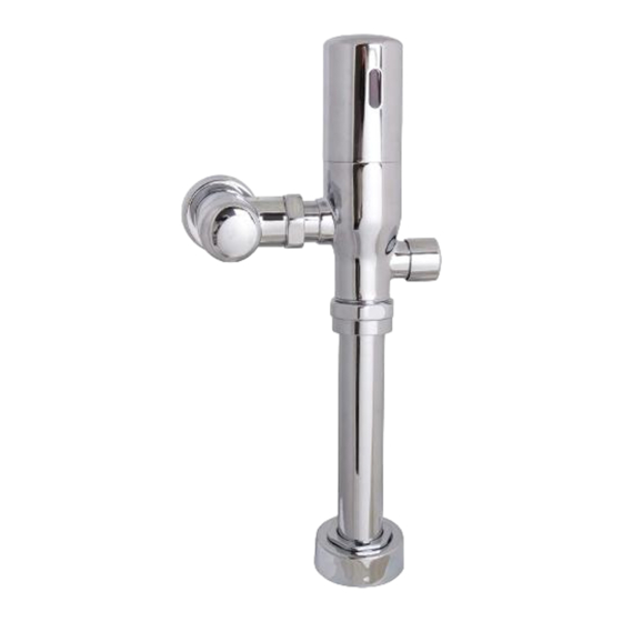
SV-4012
SV-4016
Sensor Flushometer
92-SV-401X-02
NEED HELP?
For additional assistance or service please contact:
ROUGH IN OF SUPPLY PIPE
Before you begin: Your supply pipe must be properly located. The pipe should be no more than
1
11 ½" above the fixture surface (measured to the centerline of the supply pipe), and within 4-5/16"
to 5-5/16" to the left or right of the fixture's spud (measured from centerline to centerline). This
product has the ability to receive a supply line from the left or right. Simply rotate the position of the
Valve Body Cover to adapt. See rough-in.
1"
FROM CENTERLINE
OF SPUD
(25.4mm)
2-1/4" MIN
(57mm)
NOTE: If you are cutting the vacuum breaker tube to size, consult local plumbing codes to ensure
that the critical line is properly located above the fixture. Typically, the critical line is 6" above the fixture.
TOOLS & SUPPLIES NEEDED
Measuring
Tubing
Tape
Cutter
Deburring
Solder Kit
Tool
2.5mm Hex Key
Flat Tip
Wrench
Screwdriver
(included)
Bucket
Strap
Wrench
Eye Protection
800-537-2107
www.speakman.com
4-5/16" MIN
5-5/16" MAX
(110mm-135mm)
1"
SUPPLY
11-1/2" MAX
(292mm)
IMPORTANT
Hacksaw
SAFETY TIPS:
Be sure to read and understand all instructions
before beginning installation.
Inspect all connections after installation.
Cover the drain to avoid loss of parts.
Be sure to wear proper eye protection.
Level
Do NOT over tighten any connections or damage
may occur.
Shut OFF water supplies before beginning
installation.
Observe all local plumbing and building codes.
Do NOT used toothed wrenches on any part of
the Flushometer. This will damage the finish and
void the finish warranty.
Phillips
Do NOT use pipe sealant/plumbing grease/etc.
Screwdriver
on any threaded connection except for the
connection between the control stop body and the
supply pipe.
VALVE SPECIFICATIONS:
EPA regulation prohibits using a higher flushing
volume than is described on the product and/or
tampering with the flow controller inside of the
adjustable tail piece.
Thread Seal
Tape
CAUTION
Ensure proper structure is in place to support the
Valve and plumbing during use.
Be sure to wear proper eye protection during
installation.
If your Supply Pipe is already threaded and is the proper length per the rough-in diagram, skip
2
to STEP 4.
A. Cut supply pipe 1" back from the center line of the fixture's spud using a hacksaw or tubing
cutter.
B. Deburr both the inside and outside of the supply pipe.
FROM CENTERLINE
1"
OF SPUD
(25.4mm)
3
A. Slide the Threaded NPT Adapter fully over the cut and chamfered supply pipe.
B. Sweat solder the Adapter to the pipe using soldering wire and torch.
While designed for years of trouble-free
performance, this product contains several
mechanical and electrical components that are
subject to normal wear and tear. These
components should be inspected on a regular
basis to ensure this product is working properly.
These components include but are not limited to,
the Control Stop, internal O-Rings and Seals,
Sensor Eye Mechanism, Solenoid Mechanism,
Piston, Override Button Assembly, and Vacuum
Breaker. Repair kits are available for purchase for
each of the components given above as well as
components that will need to be serviced less
frequently, such as the spud nut assembly and
inlet piping assembly. See "Repair Parts" section
of this document for a full list of repair kits that are
offered for this product.
NOTE: Regulations prohibit using replacement
parts for this product that would increase the
flushing volume beyond what is stated on the
label. As such, replacement parts are not designed
or intended to be interchangeable with parts that
would cause this product to exceed said flushing
volume.
Battery replacement will be the most common
maintenance item. Standard AA alkaline batteries
will supply approximately 335,000 flush cycles.
Frequency of battery replacement will be
determined by how often the flushometer is
activated. This product is equipped with a low
battery warning system to notify you when
replacement is required. See troubleshooting
guide for additional information.
FINISH MAINTENANCE:
Your new product is designed for years of
trouble-free performance. Keep it looking new
by cleaning it periodically with a soft cloth. Avoid
abrasive cleaners, steel wool, and harsh
chemicals as these will dull the finish and void
your warranty.
PREPARE SUPPLY PIPE
B
2-1/4" MIN
(57mm)
SOLDER THREADED ADAPTER
A
MAINTENANCE
A
B
Advertisement
Table of Contents

Related Manuals for Speakman SV-4012


Summary of Contents for Speakman SV-4012
- Page 1 INSTALLATION INSTRUCTIONS TOOLS & SUPPLIES NEEDED IMPORTANT MAINTENANCE SV-4012 Measuring Tubing Hacksaw While designed for years of trouble-free SAFETY TIPS: Tape Cutter performance, this product contains several Be sure to read and understand all instructions SV-4016 mechanical and electrical components that are before beginning installation.
- Page 2 INSTALL ESCUTCHEON TRIM INSTALL CONTROL STOP A. Measure from the finished wall to the first thread of the Adapter. Cut the Cover Tube to this length. A. Apply Thread Sealant Tape to the Threaded Pipe Adapter. B. Slide Escutcheon over the supply pipe until it is against the wall. B.
-
Page 3: Install Batteries
LUBRICATE VALVE BODY O-RING INSTALL VALVE BODY Remove protective covering from the Valve Body Inlet. Slide the Nut and Locking Ring towards the A. Insert the Valve Body into the Control Stop. Valve Body to reveal the O-ring. Lubricate the O-ring with water. B. -
Page 4: Product Warranty
Consumer/Residential: Limited Lifetime Warranty Commercial Use: 5 Year Limited Warranty Speakman warrants to its purchasers only (“Buyer”) that goods are sold free from defects in materials and workmanship and conform to Speakman’s specifications at the time of manufacturing, provided the goods are properly installed and maintained. -
Page 5: Rough-In Diagram
6" [152mm] MAX Inlet: 1” NPT Female Outlet: 1-1/2” NPSM " " 28mm 65mm FLOW RATE 1"-11 1/2 1/2" [13mm] MIN SV-4012 1.28 GPF NPT THREAD " 1 1/2" [38mm] MAX 17 5 " SV-4016 1.60 GPF 35mm 440mm NOTES 11 1 "... -
Page 6: Troubleshooting
TROUBLESHOOTING Note: Before performing any service or troubleshooting, turn off the water supply at the control stop and if possible, flush out remaining water in the flushometer. 1. The Sensor is Not Detecting a User, or the Valve is Not Flushing. a.
Need help?
Do you have a question about the SV-4012 and is the answer not in the manual?
Questions and answers