Table of Contents
Advertisement
Quick Links
Base Serial Number: _ _ _ _ _ _ _ _ _ _ _ _ _
Purchased Date: ___ / ___ / ______
Dealer's Name:__________________________
Please register your products at:
https://www.bodycraft.com/product-registration/
Power Rack
F730
& additional information,
Owner's Manual
1
To see in
FULL COLOR
scan this QR code.
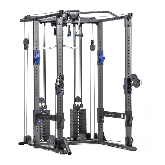
Shown with available options
F732, F734, F735, F737, F739
Open your Camera
App and point it at
the QR Code
F730 v1.2
Advertisement
Table of Contents

Related Manuals for BodyCraft F730


Summary of Contents for BodyCraft F730
- Page 1 F732, F734, F735, F737, F739 Base Serial Number: _ _ _ _ _ _ _ _ _ _ _ _ _ Purchased Date: ___ / ___ / ______ Dealer’s Name:__________________________ Please register your products at: https://www.bodycraft.com/product-registration/ Owner’s Manual F730 v1.2...
- Page 2 This page intentionally left blank...
- Page 3 Your BODYCRAFT machine has all the quality and design elements to make your workout extremely efficient and comfortable. Your new unit is a serious strength training machine that will keep you motivated, challenged and within reach of your fitness goals.
-
Page 4: Table Of Contents
Machine Options (F732, F734, F735, F737, & F739) …………………… Machine Dimensions (F730) & Options ……………………………………… Assembly Parts List ………………………………………………………… Assembly Parts Hardware ………………………………………………….. Product Assembly - How to Assemble to F730 Power Rack PreAssembly Tips ………………………………………………………..Decision Point & STEP 1……………………………………....15 - 25 STEP 2a thru STEP 6b - Main Assembly Procedures ………………. -
Page 5: Product Safety
It is imperative that you retain these Assembly Instructions and be sure all warning labels are legible and intact. Replacement Assembly Instructions and labels are available from BODYCRAFT. If you are unsure about the proper use of the BODYCRAFT strength machine call your local BODYCRAFT dealer or our Customer Service Department. Contact BODYCRAFT at 800-990-5556 or support@bodycraft.com... -
Page 6: Important Notes, Recommended Tools & Cleaners
Important Notes, Recommended Tools & Cleaners Important Notes and Tips: Before assembly, read all instructions thoroughly and preview diagrams to help make the installation easier. 2. Make sure all parts are accounted for and in proper condition before beginning assembly. See the parts list. -
Page 7: Warning Labels, Maintenance Schedule - Details
Warning Labels, Maintenance Schedule & Serial Number - F730 Carefully read ALL warning, caution & maintenance schedule labels... - Page 8 Warning Labels, Maintenance Schedule & Serial Number Placement - F730 Carefully read ALL Warning, Caution & Maintenance Schedule labels...
-
Page 9: Machine Options (F732, F734, F735, F737, & F739)
Machine Options - F730 F732, F734, F735, F737, and F739 F735 - Olympic options can be installed during Plate Rack Option assembly STEPS 2c - 5d F732 - Dip Bar Attachment F734 F734 -Band Pegs Attachment F737 - Landmine Option... -
Page 10: Machine Dimensions (F730) & Options
Machine Dimensions - F730 & Options F730 Overall Dimensions 49.5” W x 52.6” D x 82.4” H F730 (ONLY) F730 w/ F732, F734, F735, F737 & F739 Options Overall Dimensions 106.5 W x 68.2” D x 82.4” H F730 (w/ Options) -
Page 11: Assembly Parts List
Assembly Parts - F730 1 of 2 Part # Assembly Parts List F730-001-ASM Frame, Bottom, Rear - Assembly F730-002-L-ASM Frame, Bottom, Left - Assembly F730-003-R-ASM Frame, Bottom, Right w/ Serial # - Assembly F730-004 Upright, Front, 78 1/2" (1,992mm), Longer F730-005 Upright, Rear, 76 3/4"... -
Page 12: Assembly Parts Hardware
Assembly Parts - Hardware - F730 2 of 2 Part # Assembly Hardware F730-017 Washer, Spring 3/8″ - BLACK F730-022 Bolt, Hex 1/2″ x 4-1/4″ - BLACK F730-023 Bolt, Hex 1/2″ x 4″ - BLACK F730-024 Bolt, Hex 1/2″ x 2-1/2″ - BLACK F730-025 Bolt, Hex 3/8″... -
Page 13: Preassembly Tips
Product Assembly - Preassembly Tips PREASSEMBLY TIP #1 – “Stage Right”. During the assembly process we will be stating Right, Left, Front, Back, Top, or Bottom. These all are in the perspective of the user in the machine facing outward with feet on the ground. See below images as examples. -
Page 14: Decision Point & Step 1
Product Assembly - Decision Point & F730 STEP 1 DECISION POINT If you are building a complete RFT: F730 Power Rack (Base) If you are ONLY building the F730 F738 Rack Functional Trainer Power Rack, then start on STEP 1 below. -
Page 15: Step 2A Thru Step 6B - Main Assembly Procedures
Product Assembly - F730 - STEP 2a, 2b Please Hand Tighten All Bolts Until STEP 7 Recommended Tools 3/4 SOCKET & 3/4 WRENCH 6” EXTENSION TEP 2a-b: Installation of the Rear Uprights Attach both Upright, Rear, 76-3/4“, shorter ones (5) to the Frame, Bottom Right - Assembly (3-ASM) and the Frame, Bottom Left - Assembly (2-ASM) using: ●... - Page 16 Product Assembly - F730 - STEP 2c, 2d Overview NOTE: Shown with the F737 Landmine Option and F739 Battle Rope Hook Option. These options can be mounted to either side.
- Page 17 Product Assembly - F730 - STEP 2c Please Hand Tighten All Bolts Until STEP 7 TEP 2c: Installation of the Front Uprights Attach the Upright, Front, 78-1/2“, taller ones (4) to the Frame, Bottom Right - Assembly (3-ASM) using: ●...
- Page 18 Product Assembly - F730 - STEP 2d Please Hand Tighten All Bolts Until STEP 7 TEP 2d: Installation of the Front Uprights Attach the Upright, Front, 78-1/2“, taller ones (4) to the Frame, Bottom Left - Assembly (2-ASM) using: ●...
- Page 19 Product Assembly - F730 - STEP 3a, 3b TEP 3a - 3b: Installation of the Safety Arm Assemblies Attach the Safety Arm, Right & Left - Assembly (9R-ASM, 9L-ASM) to the Upright, Back (5) and Upright, Front (4). Double confirm the Bar Catch is at the front facing forward.
- Page 20 Product Assembly - F730 - STEP 3c, 3d View from frontside w/ Bar Catch View from backside w/ facing to the front. Pop-Pin Knob (13) TEP 3c - 3d: Installation of the Bar Catch Assemblies Attach the Bar Catch, Right & Left - Assembly (10R-ASM, 10L-ASM) to the Uprights, Back (5).
- Page 21 Product Assembly - F730 - STEP 4a, 4b TEP 4a - 4b: Installation of the Top Frame Rt & Lt Attach the Frame, Top, R & L (7) to the Upright, Front (4) on both right & left sides using: ●...
- Page 22 Product Assembly - F730 - STEP 5a, 5b Please Hand Tighten All Bolts Until STEP 7 TEP 5a - 5b: Installation of the Top Frame Rear Attach the Frame, Rear, Top (6) to both the Frame, Top, R & L (7) using: ●...
- Page 23 Product Assembly - F730 - STEP 5c Please Hand Tighten All Bolts Until STEP 7 TEP 5c: Installation of the Top Frame Rear Attach the Frame, Rear, Top (6) to the Upright, Rear, Right Side (5) using: ● Two BOLTS, Hex 1/2"...
- Page 24 Product Assembly - F730 - STEP 5d Please Hand Tighten All Bolts Until STEP 7 TEP 5d: Installation of the Top Frame Rear Attach the Frame, Rear, Top (6) to the Upright, Rear, Left Side (5) using: ● Two BOLTS, Hex 1/2" x 2-1/2” (24) ●...
- Page 25 Product Assembly - F730 - STEP 6a, 6b Please Hand Tighten All Bolts Until STEP 7 TEP 6a - 6b: Installation of the Chin Bar Attach the Chin Bar (11) to both the Frame, Top, R & L (7) with the Backing Plates (12) using: ●...
-
Page 26: Step 7 - "Torque Time" W/ Recommended Torque Specs
Product Assembly - F730 - STEP 7 “Torque Time” Tighten ALL Bolts at this time to the Recommended Torque Specs STEP 7: “Torque Time” ● Tighten all bolts going through the frame to locking nuts, starting at the bottom and working your way up, to the recommended torque specs of 20 ft-lbs (+/- 2 lbs) ●... -
Page 27: Step 8 - Final Assembly Clean Up, Polish & Double Checks
Product Assembly - F730 - STEP 8 STEP 8a - 8c: Final Assembly Clean Up, Polish and Double Checks STEP 8a: Remove all assembly stickers, i.e. part numbers & right left circles. ● Easy to remove with fingernail or plastic scraper ●... -
Page 28: Detailed Parts List
Detailed Parts List - F730 1 of 2 Part # Detailed Parts list F730-001 Frame, Bottom, Rear F730-002 Frame, Bottom, Left F730-003 Frame, Bottom, Right w/ Serial # F730-004 Upright, Front, 78 1/2" (1,992mm), Longer F730-005 Upright, Rear, 76 3/4" (1,951mm), Shorter... - Page 29 Detailed Parts List - F730 2 of 2 Part # Detailed Parts list F730-019 Bar Catch Cover, Blue Rubber F730-020 UHMW Protective Guard, Short, on Bar Catch Adjuster F730-021 UHMW Protective Guard, Long, on Bar Catch Adjuster F730-022 Bolt, Hex 1/2″ x 4-1/4″ - BLACK F730-023 Bolt, Hex 1/2″...
-
Page 30: Parts Exploded View
Detailed Parts - Exploded View - F730 Power Rack View Keys Red dotted (large): Structural parts assembled direction. Red dotted (med): Sub-parts assembled direction. Blue dotted lines (small): Hardware assembled direction. NOTE: Parts are not to scale... -
Page 31: Required Info Before Initiating A Service Case
Service Request Required Information BEFORE Initiating a Service Case The following information is needed to help expedite troubleshooting and to ensure the correct part(s) are sent if needed for a repair: What product / model # do you have? Unit serial number? Installed by a dealer or direct sale? Date of installation? Date of service issue? -
Page 32: Product Warranty
If the item exhibits such a defect, BODYCRAFT will, at its option, repair or replace it without cost for parts. Shipping and handling charges may apply. (BODYCRAFT may require return of the part(s) or photographic evidence of the damaged part(s) prior to replacement.) Serial number is required. -
Page 33: Product Warranty Registration
The information you provide will never be distributed to any other individuals or agencies for any purpose. If you prefer to mail your warranty card, have the owner of the product complete the information below and return it to BODYCRAFT within 30 days from the date of equipment installation.
Need help?
Do you have a question about the F730 and is the answer not in the manual?
Questions and answers