Table of Contents
Advertisement
Quick Links
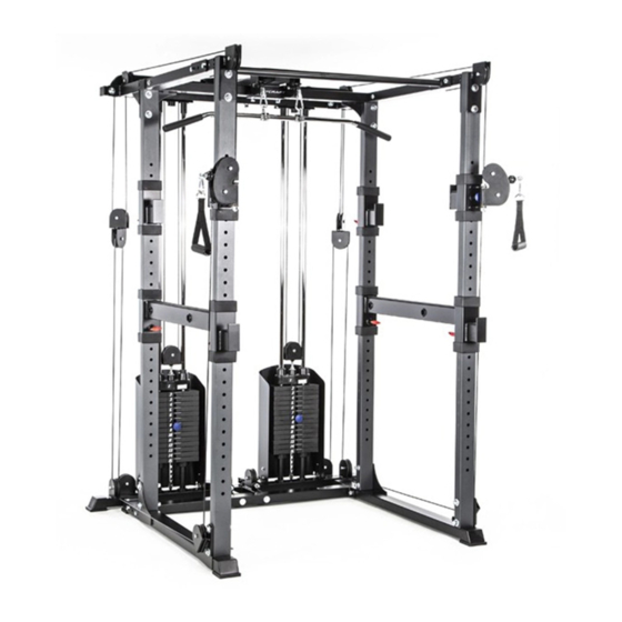
RFT - Rack Functional Trainer
F738 Functional Trainer added to the F730 Power Rack
(base unit)
FULL COLOR
Open your Camera
App and point it at
the QR Code
Base Serial Number: _ _ _ _ _ _ _ _ _ _ _ _ _
Purchased Date: ___ / ___ / ______
Dealer's Name:__________________________
Please register your products at:
https://www.bodycraft.com/product-registration/
Owner's Manual
RFT - F738 v1.2
1
Advertisement
Table of Contents

Related Manuals for BodyCraft RFT


Summary of Contents for BodyCraft RFT
- Page 1 RFT - Rack Functional Trainer F738 Functional Trainer added to the F730 Power Rack (base unit) FULL COLOR Open your Camera App and point it at the QR Code Base Serial Number: _ _ _ _ _ _ _ _ _ _ _ _ _ Purchased Date: ___ / ___ / ______ Dealer’s Name:__________________________...
- Page 2 Congratulations and Welcome to the BODYCRAFT Family Thank you for selecting BODYCRAFT. Your choice reflects a wise investment in you and your facility. We hope you use it for many healthy years! Spending 15 to 30 minutes a day, three times a week, is all you need to start seeing the benefits of a regular exercise program.
-
Page 3: Table Of Contents
Assembly Parts Hardware - F738 ……………………………………………… Assembly Parts List - F730 …………….……………………………………... Assembly Parts Hardware - F730 ……………………………………………… Product Assembly - How to Assemble an RFT - Rack Functional Trainer PreAssembly Tips ……………………………………………………………….. Understanding the Complete RFT Building Process …......Decision Point & STEP 1……………………………………...... - Page 4 Table of Contents. Page Product Assembly - How to Assemble an RFT - Rack Functional Trainer STEP 14 - Accessories - Connections & Adjustments ……….…………… STEP 15 - Weight Stack Stickers Installation ……….. ……….……………...
-
Page 5: Product Safety
It is imperative that you retain these Assembly Instructions and be sure all warning labels are legible and intact. Replacement Assembly Instructions and labels are available from BODYCRAFT. If you are unsure about the proper use of the BODYCRAFT strength machine call your local BODYCRAFT dealer or our Customer Service Department. Contact BODYCRAFT at... -
Page 6: Important Notes, Recommended Tools & Cleaners
Important Notes, Recommended Tools & Cleaners Important Notes and Tips: Before assembly, read all instructions thoroughly and preview diagrams to help make the installation easier. 2. Make sure all parts are accounted for and in proper condition before beginning assembly. See the parts list. -
Page 7: Warning Labels, Maintenance Schedule - Details
Warning Labels, Maintenance Schedule & Serial Number - RFT (F730 & F738) Carefully read ALL warning, caution & maintenance schedule labels... -
Page 8: Warning Labels, Maintenance Schedule - Placements
Warning Labels, Maintenance Schedule Placements - RFT (F730 & F738) Carefully read ALL warning, caution & maintenance schedule labels... -
Page 9: Machine Options (F732, F734, F735, F737, & F739)
Machine Options - RFT F735 - Olympic Plate Rack Option F732 - Dip Bar Attachment F734 F737 - Landmine F734 -Band Pegs Option Attachment F739 -Battle Rope Hook Option... -
Page 10: Machine Dimensions - Rft (F730 & F738) & Options
Machine Dimensions - RFT (F730 & F738) & Options RFT (F730 & F738) V2 Overall Dimensions 59.4” W x 63.1” D x 83.5” H NOTE: ● Serial # ending in V1: Height 84.3” ● Serial # ending in V2: Height 83.5”... -
Page 11: Weight Ratios - Rft (F738)
Weight Stack Ratios - RFT (F738) -
Page 12: Assembly Parts List - F738
Assembly Parts - F738 1 of 3 NOTE: For a complete service parts list, please refer to the detailed parts list & exploded view at the rear of this manual. Part # Assembly Parts List F738-201-ASM Frame, Rear, Bottom w/ Serial # - Assembly F738-202-ASM Frame, Rear, Top w/ Pulleys - Assembly F738-203-ASM Frame, Connector, Top - Assembly F738-204... - Page 13 Assembly Parts - F738 2 of 3 NOTE: For a complete service parts list, please refer to the detailed parts list & exploded view at the rear of this manual. Part # Assembly Parts List F738-222 Link Plate F738-223 Guide Rod, 1" OD x 77-3/4" L - for Weight Stacks F738-224-ASM Rotating Pulley Holder, Front, Rt &...
-
Page 14: Assembly Parts Hardware - F738
Assembly Parts - Hardware - F738 3 of 3 Part # Assembly Hardware F738-245 Washer, Flat 3/8″ - BLACK F738-246 Washer, Flat Large 1/2″ - BLACK F738-247 Washer, Flat 5/16″ - BLACK F738-254 Bolt, Hex Head 1/2″ x 2-3/4″ - BLACK F738-255 Bolt, Hex Head 1/2″... -
Page 15: Assembly Parts List - F730
Assembly Parts - F730 1 of 2 Part # Assembly Parts List F730-001-ASM Frame, Bottom, Rear - Assembly F730-002-L-ASM Frame, Bottom, Left - Assembly F730-003-R-ASM Frame, Bottom, Right w/ Serial # - Assembly F730-004 Upright, Front, 78 1/2" (1,992mm), Longer F730-005 Upright, Rear, 76 3/4"... -
Page 16: Assembly Parts Hardware - F730
Assembly Parts - Hardware - F730 2 of 2 Part # Assembly Hardware F730-017 Washer, Spring 3/8″ - BLACK F730-022 Bolt, Hex 1/2″ x 4-1/4″ - BLACK F730-023 Bolt, Hex 1/2″ x 4″ - BLACK F730-024 Bolt, Hex 1/2″ x 2-1/2″ - BLACK F730-025 Bolt, Hex 3/8″... -
Page 17: Preassembly Tips
Product Assembly - Preassembly Tips PREASSEMBLY TIP #1 – “Stage Right”. During the assembly process we will be stating Right, Left, Front, Back, Top, or Bottom. These all are in the perspective of the user in the machine facing outward with feet on the ground. See below images as examples. -
Page 18: Understanding The Complete Rft Building Process
Product Assembly - Understanding the complete RFT building process What makes an RFT - Rack Functional Trainer F730 - Power Rack (Base) F738 - Functional Trainer RFT - Rack Functional Trainer for the Power Rack Part #s: 001 - 039... -
Page 19: Decision Point & Step
Product Assembly - RFT - Decision Point & STEP 1 DECISION POINT If you currently have an F730 - Power Start on STEP 1 if you are simultaneously Rack assembled and you are adding assembling the RFT - Rack Functional Trainer:... -
Page 20: Step 2A Thru Step 6E - Main Frame Assembly
Product Assembly - RFT - STEP 2a, 2b Please Hand Tighten All Bolts Until STEP 9 Recommended Tools 3/4 SOCKET & 3/4 WRENCH 6” EXTENSION TEP 2: Installation of the Rear Uprights (F730 Parts & Hardware) Attach both Upright, Rear, 76-3/4“, shorter ones (5) to the Frame, Bottom Right - Assembly (3-ASM) and the Frame, Bottom Left - Assembly (2-ASM) using: ●... - Page 21 Product Assembly - RFT - STEP 2c, 2d - Overview NOTE: Shown with the F737 Landmine Option and F739 Battle Rope Hook Option. These options can be mounted to either side.
- Page 22 Product Assembly - RFT - STEP 2c Please Hand Tighten All Bolts Until STEP 9 TEP 2c: Installation of the Front Uprights (F730 & F738 Parts) Attach the Upright, Front, 78-1/2“, taller ones (4) to the Frame, Bottom Right - Assembly (3-ASM) and the Pulley Connector Plate, Bottom, Right (212) using: ●...
- Page 23 Product Assembly - RFT - STEP 2d Please Hand Tighten All Bolts Until STEP 9 TEP 2d: Installation of the Front Uprights (F730 & F738 Parts) Attach the Upright, Front, 78-1/2“, taller ones (4) to the Frame, Bottom Left - Assembly (2-ASM) and the Pulley Connector Plate, Bottom, Left (213) using: ●...
- Page 24 Product Assembly - RFT - STEP 3a, 3b TEP 3a - 3b: Installation of the Safety Arm Assemblies (F730 Parts) Attach the Safety Arm, Right & Left - Assembly (9R-ASM, 9L-ASM) to the Upright, Back (5) and Upright, Front (4). Double confirm the Bar Catch is at the front facing forward.
- Page 25 Product Assembly - RFT - STEP 3c, 3d View from frontside w/ Bar View from backside w/ Catch (240) facing to the front. Pop-Pin Knob (13) TEP 3c - 3d: Installation of the Bar Catch Assembly (F730 Parts) Attach the Bar Catch, Right & Left - Assembly (10R-ASM, 10L-ASM) to the Uprights, Back (5).
- Page 26 Product Assembly - RFT - STEP 3e, 3f TEP 3e - 3f: Installation of the Bar Catch Assemblies (F738 Parts) Attach the Bar Catch, Right & Left - Assembly (205-ASM, 206-ASM) to the Uprights, Front (4). NOTE: Pull outward on the Pop-Pin...
- Page 27 Product Assembly - RFT - STEP 4a, 4b TEP 4a - 4b: Installation of the Top Frame Rt & Lt (F730 & F738 Parts) Attach the Frame, Top (7) and the Pulley, Connector Plate (214) to the Upright, Front (4) on both right &...
- Page 28 Product Assembly - RFT - STEP 4c, 4d Please Hand Tighten All Bolts Until STEP 9 TEP 4c - 4d: Installation of the Top Frame Rear (F730 Parts & Hardware) Attach the Frame, Rear, Top (6) to both the Frame, Top, R & L (7) using: ●...
- Page 29 Product Assembly - RFT w/ F735 Option - STEP 4e Please Hand Tighten All Bolts Until STEP 9 TEP 4e: Installation of F735 Option - Rt Side (F735 Parts) ● Two BOLTS, Hex 1/2" x 3-1/4” (508) Attach the Olympic Plate Rack Option - Right Side (F735 - RT - ASM) to the Upright, Rear, Right Side (5) using: ●...
- Page 30 Product Assembly - RFT w/ F735 Option - STEP 4f Please Hand Tighten All Bolts Until STEP 9 TEP 4f: Installation of F735 Option - Lt Side (F735 Parts) Attach the Olympic Plate Rack Option - Left Side (F735 - LT - ASM) to the Upright, Rear, Right Side (5) using: ●...
- Page 31 Product Assembly - RFT - STEP 5a Please Hand Tighten All Bolts Until STEP 9 TEP 5a: Installation of the Top Frame Connector (F738 Parts) Attach the Frame, Connector, Top - Assembly (203) to the Frame, Rear, Top (6) with the Link Plate (222) using: ●...
- Page 32 Product Assembly - RFT - STEP 5b Please Hand Tighten All Bolts Until STEP 9 TEP 5b: Installation of the Chin Bar (F730 & F738 Parts & Hardware) Attach the Chin Bar (11) to both the Frame, Top, R & L (7) with the Backing Plates (12) using: ●...
- Page 33 Product Assembly - RFT - DECISION POINT & STEP 6 DECISION POINT If you DID NOT install the F735 Olympic If you DID install the F735 Olympic Plate Plate Rack Option during STEP 4, use Rack Option during STEP 4, keep the the following hardware for STEP 6a.
- Page 34 Product Assembly - RFT - STEP 6a Please Hand Tighten All Bolts Until STEP 9 Recommended Tools 3/4 WRENCH 3/4 SOCKET & STEP LADDER or 6” EXTENSION STEP PLATFORM TEP 6a: Installation of the Rear Frame Top Connectors (F738 Parts) Attach the Frame, Rear, Top, Connectors Right &...
- Page 35 Product Assembly - RFT - STEP 6b Please Hand Tighten All Bolts Until STEP 9 TEP 6b: Installation of the Rear Frame w/ Pulleys (F738 Parts) Attach the Frame, Rear, Top w/ Pulleys (202) to both the Frame, Connector, Rear, Top, Right & Left (207, 208) using: ●...
- Page 36 Product Assembly - RFT - STEP 6c Please Hand Tighten All Bolts Until STEP 9 DOUBLE CONFIRM View from inside the machine with the #221-ASM Accessory Hook Plate facing inward to the front. TEP 6c: Installation of the Hook Plate for Accessories (F738 Parts) Attach the Hook Plate for Accessories (211) to both the Frame, Rear, Top w/ Pulleys (202) using: ●...
- Page 37 Product Assembly - RFT - STEP 6d Please Hand Tighten All Bolts Until STEP 9 Recommended Tools 3/4 SOCKET & 3/4 WRENCH 6” EXTENSION TEP 6d: Installation of the Rotating Pulley Holders at the Bottom Frame, Rt & Lt (F738 Parts) Attach the Rotating Pulley Holders, Bottom Frame, Right &...
- Page 38 Product Assembly - RFT - STEP 6e Please Hand Tighten All Bolts Until STEP 9 TEP 6e: Installation of the Rear Bottom Frame w/ Serial # (F738 Parts) Attach the Frame, Rear, Bottom w/ Serial # to the F730 Frame Rear Bottom Assembly (1-ASM) using: ●...
-
Page 39: Step 7A Thru Step 7M - Weight Stack Assembly
Product Assembly - RFT - STEP 7a, 7b TEP 7a: Installation of the Guide Rod Holders (F738 Parts) Attach the Guide Rod Holders, Plastic (238) to the Frame, Rear, Bottom w/ Serial # (201-ASM) on both the right & left sides. - Page 40 Product Assembly - RFT - STEP 7c STEP 7c: Lube all four Guide Rods Lube at this time only the lower half with 100% pure Silicone Lube or Teflon PTFE grease. Top half will be done later. This potentially keeps lube from not getting on the installers clothes during the next few assembly steps.
- Page 41 Product Assembly - RFT - DECISION POINT & STEP 7d DECISION POINT 150 lb OPTIONAL 200 lb Weight Stack Weight Stack If you are installing the 150 lb Weight If you are installing the OPTIONAL Stacks, use the Stack Spacers (230).
- Page 42 Product Assembly - RFT - STEP 7e TEP 7e: Installation of the Stack Spacers & Rubber Cushions (F738 Parts) With the Guide Rods (223) angled slightly, slide on the Stack Spacers (230) & Rubber Cushions (237) to the Guide Rods (223), both the right & left sides.
- Page 43 Product Assembly - RFT - STEP 7f TEP 7f: Installation of the Weight Plates (F738 Parts) With the Guide Rods (223) angled slightly, slide on the Weight Plates (234) one at a time onto the Guide Rods (223), both the right & left sides.
- Page 44 Product Assembly - RFT - STEP 7f - Double Confirm TEP 7f: Double Confirm - Weight Stacks (F738 Parts) This is the BEST TIME to stop and look at what has been assembled at this time on the weight stacks.
- Page 45 Product Assembly - RFT - STEP 7g, 7h, 7i TEP 7g: Preassembly of the Selector Pin (F738 Parts) Attach the Selector Pin w/ Lanyard (225) over the Pulley Block w/ shaft 1/2“- Assembly (211-ASM) using: ● One NUT, Hex 1/2" (269)
- Page 46 Product Assembly - RFT - STEP 7j TEP 7j: Installation of the Top Plate (F738 Parts) Slide on the Top Plate - Assembly (226-ASM) to the Guide Rods (223), both the right & left sides.
- Page 47 Product Assembly - RFT - STEP 7k TEP 7k: Installation of the Top Guide Rod Holder Plate (F738 Parts) Loosen or take out the pre-assembled Inner Hex Screws (261). Then slide on the Top Guide Rod Holder Plate - Assembly (209-ASM) to the Guide Rods (223), both the right & left sides.
- Page 48 Product Assembly - RFT - STEP 7l, 7m, 7n TEP 7l: Securing the Top Guide Rod Holder Plate (F738 Parts) Attach the Top Guide Rod Holder Plate - Assembly (209-ASM) to the Frame, Rear, Top w/ Pulleys (202) using: ●...
-
Page 49: Step 8A Thru Step 8D - Pulley Holders Assembly
Product Assembly - RFT - STEP 8a, 8b TEP 8a - 8b: Installation of the Rotating Pulley Holders on the Front, Rt & Lt (F738 Parts) Attach the Rotating Pulley Holder, Front, Right & Left - Assemblies (224-ASM) to the Bar Catch, Right &... - Page 50 Product Assembly - RFT - STEP 8c, 8d Please Hand Tighten All Bolts Until STEP 9 Recommended Tools 3/4 WRENCH 3/4 SOCKET & STEP LADDER or 6” EXTENSION STEP PLATFORM TEP 8c - 8d: Installation of the Rotating Pulley Holders on the Top Connector Frame, Rt &...
-
Page 51: Step 9 - "Torque Time" W/ Recommended Torque Specs, Frame
Product Assembly - F738 - STEP 9 “Torque Time” STEP 9: “Torque Time” on Main Frame Bolts & Nuts These recommended torque specs should be followed for correct assembly and safe operation of this machine. Example of being overtightened not using the recommended torque specs. -
Page 52: Rft - Cable & Pulley Tips
Product Assembly - RFT - Cable & Pulley TIPS TIP: Using a Step Ladder takes the installer at EYE level for easier assembly of cables & pulleys. Recommended Tools TIP: Confirm the cables are riding on the pulleys and the swivel pulley frame is not too tight ie. -
Page 53: Step 10A Thru Step 12D - Cables Assembly & Adjustments
Product Assembly - RFT - STEP 10 - Pulley & Cable Overview Please Hand Tighten All Bolts Until STEP 13 Round Plastic Ball Spring Clip end at end at Pulley #1 Pulley #11 Finished with Spring Clip end at Pulley #11... - Page 54 Product Assembly - RFT - STEP 10a, 10b TEP 10a - 10b: Assemble the Top Cable (219) with Pulleys P1 - P6 (228). TEP 10b TEP 10a Recommended Tools Hardware assembly for each pulley: ● One BOLT, Hex 3/8” x 2” (260) 9/16 SOCKET &...
- Page 55 Product Assembly - RFT - STEP 10c, 10d TEP 10c - 10d: Assemble the Top Cable (219) with Pulleys P7 - P11 (228). TEP 10d TEP 10c Hardware assembly for each pulley: ● One BOLT, Hex 3/8” x 2” (260) ●...
- Page 56 Product Assembly - RFT - STEP 11 - Pulley & Cable Overview Please Hand Tighten All Bolts Until STEP 13 Round Plastic Ball Bolt w/ nut end at Cable end at Pulley #12 End Bolt Holder Finished with Bolt w/ nut...
- Page 57 Product Assembly - RFT - STEP 11a TEP 11a: Assemble the Bottom Cable (220) starting with Pulley P12 (229). NOTE: These are the only two Pulleys (229) that are larger at 4-½” (114mm). TEP 11a Recommended Tools 9/16 SOCKET &...
- Page 58 Product Assembly - RFT - STEP 11b, 11c TEP 11b - 11c: Assembly of Bottom Cable (220) with Pulleys P13 - P16 (228) to the Cable End Bolt Holder. TEP 11c TEP 11b Hardware assembly for each pulley: ● One BOLT, Hex 3/8” x 2” (260) ●...
- Page 59 Product Assembly - RFT - STEP 12a TEP 12a: Cable Adjustment Adjust cables to correct tension with less than 1/2” of play in cables. Confirm the Cable End Bolt into the Cable Bolt Holder has a MAX 1” of threads showing.
-
Page 60: Step 9 - "Torque Time" W/ Recommended Torque Specs, Pulleys
Product Assembly - RFT - STEP 13 “Torque Time” STEP 13: “Torque Time” on all Pulleys & Cable Adjustment Hardware 17 ft-lbs (+/- 2 lbs) 17 ft-lbs 22 ft-lbs (+/- 2 lbs) (+/- 2 lbs) Tighten all Bolts securing Pulleys (P1-P16 on both right & left sides) to the recommended torque specs of 17 ft-lbs (+/- 2 lbs) on all 3/8”... - Page 61 Product Assembly - RFT - STEP 14 - Cable Accessories TEP 14a: Cable Accessories for the RFT - Rack Functional Trainer to use on the Pulleys and/or stored on the Hook Plate for Accessory (221-ASM) in the back, top of machine:...
- Page 62 Product Assembly - RFT - Accessories Connections & Operations of Adjustments Extension chains (223) add the extra needed length to start any exercise with the given accessories. Just place the Snap Hooks on the desired chain-link location for the exact additional length needed. Then attach another end to the cable pulley end on the machine.
- Page 63 Product Assembly - RFT - STEP 15 - Weight Stack Stickers Installation...
- Page 64 Product Assembly - RFT - Final Assembly Lube, Clean up, & Polish STEP 16a: Lube all Four Guide Rods (223) with 100% pure Silicone Lube or Teflon PTFE Grease ONLY apply a light layer with a clean rag. Then do a set of reps with low weights to spread the lubricant thoroughly on the Guide Rods (223).
- Page 65 Product Assembly - RFT - Final Assembly Clean up, Lube & Polish STEP 16b - 16c: Final Assembly Clean Up & Polish STEP 16b: Remove all Assembly Stickers, i.e. Part Numbers & Right / Left Circles ● Easy to remove with fingernail or plastic scraper ●...
- Page 66 Product Assembly - RFT - Assembly is Complete & Double Confirm Checks Double Confirm Checks at this Time: ● All Bolts, Nuts and Pop-Pins are tightened ● All Safety Arms and Bar Catches move smoothly ● All Pop-Pins fully engage into the upright holes ●...
- Page 67 Product Assembly - RFT - STEP UPGRADE: F730 to an RFT TEP UPGRADE a: Disassembly of the Chin Bar - F730 Parts & Hardware Take off the Chin Bar (11) from both the Frame, Top, Rt & Lt (7) & the Backing Plates (12) removing: ●...
- Page 68 Product Assembly - RFT - STEP UPGRADE: F730 to an RFT TEP UPGRADE c: Disassembly of the Top Frame Rt & Lt - F730 Parts & hardware Take off the Frame, Top, Right & Left Sides (7) from the Upright, Front (4) removing: ●...
- Page 69 Product Assembly - RFT - Routine Schedule...
- Page 70 Product Assembly - RFT - General & Cable Inspection...
- Page 71 Product Assembly - RFT - Lubrication Maintenance...
- Page 72 Product Assembly - RFT - Strength Cable Wear Indicators...
- Page 73 Detailed Parts List - F738 1 of 2 Part # Detailed Parts list F738-201 Frame, Rear, Bottom w/ Serial # F738-202 Frame, Rear, Top w/ Pulleys F738-203 Frame, Connector, Top F738-204 Lat Bar F738-205 Pulley Height Adjuster, Right F738-206 Pulley Height Adjuster, Left F738-207 Frame, Connector, Rear, Top, Right F738-208...
- Page 74 Detailed Parts List - F738 2 of 2 Part # Detailed Parts list F738-240 Bar Catch Cover, Blue Rubber F738-242 Bushing, Brass, φ12.7 * φ16 * φ22, (1/2" ID) F738-243 Foot Pad, Rubber F738-244 Stopper F738-245 Washer 3/8″ - BLACK F738-246 Washer, Large 1/2″...
- Page 75 Detailed Parts Exploded View - F738 1 of 2...
- Page 76 Detailed Parts Exploded View - F738 2 of 2...
- Page 77 Detailed Parts List - F730 1 of 2 Part # Detailed Parts list F730-001 Frame, Bottom, Rear F730-002 Frame, Bottom, Left F730-003 Frame, Bottom, Right w/ Serial # F730-004 Upright, Front, 78 1/2" (1,992mm), Longer F730-005 Upright, Rear, 76 3/4" (1,951mm), Shorter F730-006 Frame, Top, Rear F730-007...
- Page 78 Detailed Parts List - F730 2 of 2 Part # Detailed Parts list F730-019 Bar Catch Cover, Blue Rubber F730-020 UHMW Protective Guard, Short, on Bar Catch Adjuster F730-021 UHMW Protective Guard, Long, on Bar Catch Adjuster F730-022 Bolt, Hex 1/2″ x 4-1/4″ - BLACK F730-023 Bolt, Hex 1/2″...
- Page 79 Detailed Parts - Exploded View - F730 Power Rack View Keys Red dotted (large): Structural parts assembled direction. Red dotted (med): Sub-parts assembled direction. Blue dotted lines (small): Hardware assembled direction.
- Page 80 Service Request Required Information BEFORE Initiating a Service Case The following information is needed to help expedite troubleshooting and to ensure the correct part(s) are sent if needed for a repair:...
- Page 81 If the item exhibits such a defect, BODYCRAFT will, at its option, repair or replace it without cost for parts. Shipping and handling charges may apply. (BODYCRAFT may require return of the part(s) or photographic evidence of the damaged part(s) prior to replacement.) Serial number is required.
- Page 82 The information you provide will never be distributed to any other individuals or agencies for any purpose. If you prefer to mail your warranty card, have the owner of the product complete the information below and return it to BODYCRAFT within 30 days from the date of equipment installation.
- Page 83 This page intentionally left blank...
Need help?
Do you have a question about the RFT and is the answer not in the manual?
Questions and answers