Table of Contents
Advertisement
Quick Links
Advertisement
Table of Contents

Subscribe to Our Youtube Channel
Related Manuals for Kanomax 1580


Summary of Contents for Kanomax 1580
- Page 1 Multi-Channel Anemomaster MODEL 1580 Userʻs Manual...
-
Page 3: List Of Components
List of Components ■ Multi-Channel Anemomaster Item Model Function Multi-Channel Anemomaster Up to 12-probe data integration 1580-0G main unit Communicates with PC software Multi-Channel Anemomaster Measurement start and stop on PC software 1580-40 Measured value display on PC Data management on PC... - Page 4 ■ Probe Item Model Function UNI-directional air velocity 0972-00 Digital output of air velocity values probe (Flat) UNI-directional air velocity 0973-00 Digital output of air velocity values probe (φ9) Omni-directional air velocity 0975-00 Digital output of air velocity values probe (Needle) Omni-directional air velocity 0975-09 Digital output of air velocity values...
- Page 5 ■ Optional Accessories Item Model Function 0.5 m 1580-30 2.0 m 1580-31 5.0 m 1580-32 Standard Connects the Multi-Channel Anemomaster Main cable Unit and probe(s) 10.0 m 1580-33 20.0 m 1580-34 40.0 m 1580-35 AC adapter (90W) 1580-10 Exclusive AC adapter (90W)
-
Page 6: Important Safety Information
Important Safety Information The symbols for the warnings used in this manual are defined below: Description of Symbols Warning Warnings in this classification indicate risks that may result in serious injury or death if not observed. Caution Warnings in this classification indicate risks that may result in injury or damage to the surrounding objects if not observed. - Page 7 Failure to observe the above may cause electric shock, fire, and/or damage. Please contact your local distributor or Kanomax service center for repair. Caution (Proper Handling) Pull out the plug when the instrument is not in use.
- Page 8 (Forbidden) Do not wipe the instrument with volatile solvent. The body may deform and/or deteriorate. Use soft dry cloth to remove stains. If stains persist, soak the cloth in neutral detergent and wipe the instrument with the cloth. (Forbidden)Do not use the instrument in areas where vaper is present. Touching a water droplet to the air flow element can affect the amount of the heat dissipation.
- Page 9 (Proper Handling) When storing the instrument, keep it in a place with an ambient temperature of -10 to 60℃ and no condensation. (Forbidden) Do not dispose of the instrument as household waste. Please note that the disposal of the instrument and batteries should be in line with your local or national legislations.
-
Page 10: Table Of Contents
3. Overall Flow ....................... 25 Measurement ........................ 25 Error ..........................27 4. User Interface ......................28 Multi-Channel Anemomaster Main Unit (Model: 1580-0G) ........... 28 Connection ........................ 28 Power ON/OFF ......................29 LED display ........................ 29 Multi-Channel Anemomaster PC Software (Model: 1580-40) ..........30 Main screen ....................... - Page 11 Multi-Channel Anemomaster PRO Analog Unit (Model: 1592-0G) ......... 36 Connection ........................ 36 Power ON/OFF ......................37 LED display ........................ 38 Probe ........................... 39 Connection ........................ 39 Power ON/OFF ......................39 LED display ........................ 40 Probe Cleaning ......................41 Specifications ........................ 43 6.
-
Page 12: Part Names And Functions
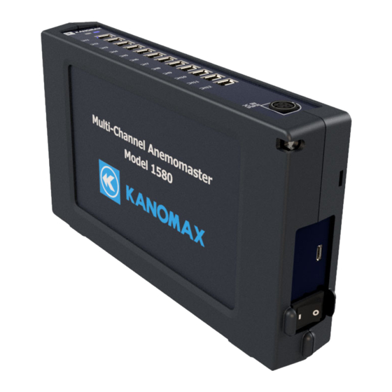
1. Part Names and Functions 1. Multi-Channel Anemomaster Main Unit(Model 1580-0G) ① ② ④ ③ ⑤ ⑥ ⑦ Name Function ① LED (Blue/Red) Displays the status of the main unit ② Probe-to-probe Communicates with the probe in the RS-485 communication terminal... -
Page 13: Multi-Channel Anemomaster Pro Analog Unit (Model 1592-0G)
2. Multi-Channel Anemomaster PRO Analog Unit (Model 1592-0G) ① ② ③ ⑤ ④ ⑥ ⑦ ⑧ Name Function ① LED (Blue/Red) Displays the status of the main unit Output an analog value set up in the Multi- Channel Anemomaster ② Analog output terminal Connects to CH to be used in the dividing (1 to 12 CH) terminal block (accessory), and wire to the... -
Page 14: Getting Ready To Measure
2. Getting Ready to Measure System configuration This system uses multiple units, cables and power supply devices combined as shown below. This chapter explains how to configure them to get ready to measurements. ・Multi-Channel Anemomaster Main Unit The main unit integrates up to 12-probe data and communicates with the PC software and the analog unit (Model: 1592-0G). - Page 15 Wrong connections can cause malfunction and/or damage. Prior to turn the power ON, read this Userʼs Manual carefully, configure each instrument in the following sequence. 1. Connect the probe fixing jig 2. Connect the probe 3. Connect the power cable 4....
-
Page 16: Connecting The Probe Fixing Jig
Connecting the probe fixing jig Only the probes 0976-03 and 0976-04, 0976-13, 0976-14 can be used to anchor the probes with the probe fixing jig. Do not use any other probe. Otherwise, malfunction or damage may occur. How to mount/remove the probe to/from the fixing jig, follow the procedure below. When mounting/removing the probe, do not allow the sensor of the probe to touch the probe fixing jig or surrounding objects. -
Page 17: Connecting The Probe
To mount the probe fixing jig to a setting place, use a sticky tape such an adhesion tape as a double-faced tape. To mount the probe fixing jig to a columnar object, as the figure shows below, attach the supplied base to the probe fixing jig and fix them with such a band as a plastic tie. Columnar object Plastic tie base... -
Page 18: Connecting The Power Source
To disconnect the standard cable (option), as the figure shows below, push and hold the release buttons, and remove the cable from the connector. Connecting the power source Be sure to supply power to the unit with the 90W AC adapter (the accessory of the main ... - Page 19 When connecting the AC adapter to the unit, as the figure shows below, the orientation of the AC adapter should be the same with the solid-lined figure of the DC power supply terminal on the unit. Be sure to insert the AC adapter in the right orientation until you feel a click.
-
Page 20: Connecting The Analog Unit
Connecting the analog unit By connecting the analog unit (Model: 1592-0G) of the Multi-Channel Anemomaster PRO, the analog output of measurement data from a connected probe becomes possible. Up to 3 analog units can be connected. Using the connecting connector, connect the Multi-Channel Anemomaster Main Unit and the analog unit. - Page 21 To disconnect the connected units, put your fingers in the hand well at the bottom face of the units, and pull the units outward. Hand well...
- Page 22 Up to 3 analog units can be connected. Do not connect 4 analog units or more. If 4 analog units or more are connected, analog output is not performed. Connect the analog unit(s) only. If anything other than the analog unit(s) is connected, ...
-
Page 23: Connecting The Analog Output
Connecting the analog output As to connection between the analog unit and the output, connect the dividing terminal block (accessory) to the analog unit, and wire to the output. Be sure to turn off the power to the analog unit during this step. Otherwise, malfunction and/or damage may occur. As to the pin layout of each CH on the analog output terminal, refer to the figure below. -
Page 24: Installing Pc Software
Installing PC Software 1) Prior to the software setup, exit other programs. Open the folder on the CD and select according to your Windows 10 version. Double click the setup file to display the dialog box as shown in Figure 2-1. Figure 2-1 Initial Setup Dialog Box Click the (N) button to display the dialog box as shown in Figure 2-2. - Page 25 3) Click the (N) button to display the dialog box as shown in Figure 2-3. Figure 2-3 Confirmation Installation Dialog Box 4) Click the (N) button to display the dialog box as shown in Figure 2-4. Figure 2-4 Installation progress Dialog Box...
-
Page 26: Connecting The Pc
5) When the installation is completed, the dialog box as shown in Figure 2-5 will appear. Figure 2-5 Installation Complete Dialog Box 6) Click the (C) button to complete the setup. Connecting the PC Using the USB cable as the accessory of the main unit, set up as below. ... -
Page 27: Overall Flow
3. Overall Flow Measurement Connect necessity appliances to measure such as the analog unit(s), the probe(s) and the AC adapter to the Multi-Channel Anamemoster Main Unit, and turn the power on to the main unit. Connect the PC installed the PC software and the Multi-Channel Anemomaster Main Unit ... - Page 28 On the measurement setting of the PC software, set up each parameter necessity to measure and click the Save button to connect. Click the start measurement button to start measurement in accordance with your setting. Measurement is finished when the set number of measurement is completed or the stop ...
-
Page 29: Error
Error The self-diagnostic function can detect the following critical error. If the error occurs, measurement cannot be started. Power voltage supplied to the connected unit is Source voltage lower/higher than the specified value. error For further information, please refer to 2. Getting Ready to Measure >... -
Page 30: User Interface
4. User Interface Multi-Channel Anemomaster Main Unit (Model: 1580-0G) Connection Name How to connect Unit-to-unit Using the standard cable (option), connect to the probe communication exchange BOX of the probe to be connected. terminal The available standard cable (option) can be selected from (1 to 12 CH) 0.5 m, 2.0 m, 5.0 m, 10.0 m, 20.0 m and 40.0 m. -
Page 31: Power On/Off
Power ON/OFF To turn the power ON/OFF, use the power switch on the side of the unit. Prior to using the power switch, make sure that the AC adapter (90W) is connected to the analog unit which is connected using the connecting connector, or to the Multi-Channel Anemomaster Main Unit. -
Page 32: Multi-Channel Anemomaster Pc Software (Model: 1580-40)
Multi-Channel Anemomaster PC Software (Model: 1580-40) Main screen Click the icon on the start-menu to start the software. File Use this menu to clear data, save a data file and close the application. ・ New Click the New on the file menu to delete displayed measurement data. -
Page 33: View
View The display style of measurement data can be selected from the Number, Graph or Statistics views. ・ Number view Click the Number view button to display the figure below. - Page 34 ・ Graph view Click the Graph view button to display the figure below. ・ Statistics view Click the Statistics view button to display the figure below.
-
Page 35: Connection
Connection The connection status of probe connected to the Multi-Channel Anemomaster Main Unit is displayed on this menu. ・ Connection status By clicking the Connection status button on the connection menu, probesʼ connection status can be checked at a first glance on the figure below. Details of connection status Click a probe number on the Connection status to check the detailed connection status of probes as the figure shows below. -
Page 36: Setting
Setting Set the measurement parameters/the main unit connection and the analog output on this menu. ・ Measurement Setting By clicking the Measurement setting button on the setting menu, the connection of the measurement parameter setting/the main unit can be set. ・... - Page 37 Help The name of the software and version information are displayed on this menu. ・ Version information By clicking the About version on the help menu, various information such as the name of the Software and the version information can be checked.
-
Page 38: Multi-Channel Anemomaster Pro Analog Unit (Model: 1592-0G)
Multi-Channel Anemomaster PRO Analog Unit (Model: 1592-0G) Connection Name How to connect Using the dividing terminal block (accessory), connect this terminal to a device to be connected such as a Analog output terminal data logger. (1 to 12 CH) For details, refer to 2. Getting Ready to Measure > Connecting the analog output. -
Page 39: Power On/Off
Using the standard cable (option), connect this terminal (DOWN) to another analog unit (UP). For details, refer to 2. Getting Ready to Measure > Connecting the analog unit. The available standard cable (option) can be selected DOWN from 0.5 m, 2.0 m, 5.0 m, 10.0 m, 20.0 m and 40.0 If the connecting connector (socket) has already been used to connect to another unit, do not use this terminal. -
Page 40: Led Display
LED display LED status Description Solution Proper operation When the LED (red) is ON, power voltage abnormality or Check the connection method. other abnormality (Blue) occurred. When the LED (red) is OFF, the Turn the power ON. power is OFF. Power voltage abnormality or other abnormality... -
Page 41: Probe
Probe Connection Prove converter Name How to connect Using the standard cable (option), connect this terminal to the probe-to-probe terminal of the Multi-Channel Hub unit-to-unit Anemomaster Main Unit communication terminal The available standard cable (option) can be selected from 0.5 m, 2.0 m, 5.0 m, 10.0 m, 20.0 m and 40.0 m. Power ON/OFF Power is supplied from the connected Multi-Channel Anemomaster Main Unit. -
Page 42: Led Display
Error occurred in the built-in If LED (red) is still ON, please CPU. contact your distributor Kanomax service center. Check the AC adapter (90 W) Flashing Power voltage is decreasing. (Red) connection on the main unit. When (green) operation is proper. -
Page 43: Probe Cleaning
Probe Cleaning Dust such as fine/soot particles or machine oil adhered to the air flow element can change the heat dissipation (the amount of heat taken away). This can affect the reading of air velocity. Probes with a wire mesh or a filter cannot read an accurate measurement value when they are clogged with such substances as dust. -
Page 45: Specifications
Specifications ■ Multi-Channel Anemomaster Main Unit Product name Multi-Channel Anemomaster Main Unit Model 1580-0G Connectable unit Multi-Channel Anemomaster PRO Analog Unit (Model 1592-0G) Model 0972-00: UNI-directional air velocity probe (Flat) Model 0973-00: UNI-directional air velocity probe (φ9) Model 0975-00: Omni-directional air velocity probe (Needle) - Page 46 ■ Multi-Channel Anemomaster PRO Analog Unit Product name Multi-Channel Anemomaster PRO Analog Unit Model 1592-0G Connectable unit Multi-Channel Anemomaster Main Unit (Model 1580-0G) Communication Unit-to-unit RS485 communication (Standard cable) function Range 0 to 5 V Voltage Output output 1 kΩ...
- Page 47 ■ Probe Measurement range Measurement accuracy Operational Temperature Model temperature compensation Velocity/Temperature/Humidi Velocity/Temperature/Humid range range/accuracy 0972-00 0.01 to 50.0 [m/s] (Velocity) 0973-00 0 to 100℃ ±2% of reading or 0975-00 0.01to 25.0 [m/s] 0 to 100℃ ±5% of ±0.02 m/s, whichever is reading 0975-09 the greater.
- Page 51 ■ Standard cable Model 1580-30 1580-31 1580-32 1580-33 1580-34 1580-35 0.5 m 2.0 m 5.0 m 10.0 m 20.0 m 40.0 m Length ± tolerances +0.05,-0 +0.1,-0 +0.2,-0 +0.3,-0 +0.5,-0 +1.0,-0 Operating 0 to 60℃, 5 to 95%RH with no condensation...
-
Page 52: Troubleshooting
Main Unit and the probe is faulty. Please contact your P.57 local distributor or KANOMAX service center for repair. The error message “P-ERROR” is displayed. → Power supply to the probe is faulty. Please contact P.57 your local distributor or KANOMAX service center for repair. -
Page 53: Warranty And After-Sales Service
PRODUCT as determined by KUI. Warranty for such replacements shall not extend the original warranty period of the defective PRODUCT. To obtain service under this warranty, you must notify Kanomax USA, Inc. on or before the expiration of the warranty period to obtain directions for returning the defective product. You are responsible for all return shipping charges to the authorized Kanomax service center. -
Page 54: Contact Information
Shenyang Kano Scientific Instrument Co., Ltd. TEL: 86-24-23846440 FAX: 86-24-23898417 URL: http://www.kanomax.com.cn/ E-mail: sales@kanomax.com.cn KANOMAX JAPAN INC. ©2021 Reprinting of part or the whole of the contents of this manual is strictly forbidden. The contents of this manual are subject to change without notice. - Page 55 01001/2109...
Need help?
Do you have a question about the 1580 and is the answer not in the manual?
Questions and answers