Advertisement
Quick Links
Advertisement

Related Manuals for Aeronaut 3033/00


Summary of Contents for Aeronaut 3033/00
- Page 1 Südersand Order-No. 3033/00...
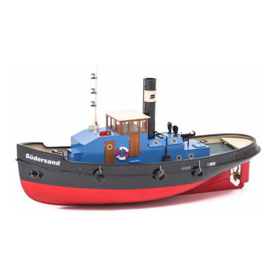
- Page 2 Südersand Thank you for buying an aero-naut kit! Südersand is the model of a small steam tug in 1:20 scale, which was in use in the 20ies and 30ies of the last century. This kit contains precisely laser-cut parts and a sheet of photo-etched brass parts for the fine details which give the model its realistic Recommended drive system (brushed motor) appearance.
- Page 3 Building the Hull Glue together two rear keel parts 6, sand edges smooth, then apply two coats of sanding sealer. Sand lightly with 400-grit sandpaper. Glue together parts 3 to 5 to assemble the boatstand. When glue has dried apply several coats of sanding sealer. Sand lightly with 400-grit sandpaper.
- Page 4 With a sanding block sand contact surface for rear keel parts 6 smooth. Position rear keel parts on contact surface of hull and check distance for rudder installation as indicated. The distance should measure 70 mm. For rear keel installation drill two 1.5 mm holes for tapping screws 9 into hull.
- Page 5 When glue has cured completely sand rudder to a The rudder consists of three layers. Glue parts 11, drop-shaped cross-section and apply two coats of 12, 13 and 14 between outer layers 15. Note that sanding sealer. locating tube 13 must be flush with lower end of rudder.
- Page 6 22.2 Insert rudder in rudder sleeve. Make sure to include 22.1 washer 19 when you do this! Protect hull along keel´s gluing surface then glue keel 6 to hull using Stabilit Express. Secure with tapping screws 9 and washers 10. When glue has cured secure rudder with screw 20.
-
Page 7: Interior Structure
Interior Structure Prepare motor mount 23 for motor installation. It is possible to install 500-type brushed motors or slow outrunners with a diameter of 28 mm. For 500-type brushed motors increase diameter of centre hole to 13 mm using a drill bit or a file (use engraved line on motor mount as a guide). Place side panel 25 flat on the building board. - Page 8 Screw motor to motor mount using socket head screws and washers. Note: It makes sense to install the motor using socket head screws. This will make it easier to remove the motor, once the RC support structure has been installed. Place sub deck 26 flat on the building board, fit support structure in place on sub deck and check for proper fit.
- Page 9 Remove prop shaft from stern tube, insert stern tube in hull so that it protrudes from hull by approximately 3 mm. Insert prop shaft in stern tube, install spacer and secure with M4 nut. Temporarily install prop (diameter 50 mm) on prop shaft. There should be a distance of about 5 mm between rudder and prop hub.
- Page 10 Coaming Glue together coaming parts 30, 31 and 32 upside down on a flat surface or building board. Corner reinforcements 32 make sure that parts are glued at right angles. Note: Arrow symbols on coaming face forward and upward on completed assembly when installed in deck opening.
- Page 11 36.1 To the underside of deck 34 glue support frames 35 and 36.1 for coal hole covers and rudder linkage access hatch cover. Make sure support frames are exactly centred over openings. Immediately remove any excess glue from the inside of openings. Then place suitable weights on frames until glue has dried.
- Page 12 Lightly sand contact surfaces of deck and hull. Position deck as accurately as possible on hull, glue in place and secure with clamps until glue has dried. Note: Use glue that reliably bonds styrene to wood, for example Ruderer L530 or Stabilit Express.
- Page 13 Position template S1 on outside of bulwark so that rear end of wash Cut out second wash port at a distance of 50 mm from first wash port. port corresponds with rear end of the coaming. Draw contour of wash port onto bulwark with a soft pencil, then use Repeat this procedure on opposite side of bulwark.
- Page 14 Glue mooring ports 37 into bulwark. From the inside glue parts 39 onto neck of mooring ports. Remove wash ports 38 from set of photo etched parts and glue to the outside of bulwark. From below drill hawser holes for anchors 40 with 2.5 mm at a steep angle.
- Page 15 Drill three 1.5 mm holes into bulwark for fender ropes. Use thread 42 to tie fenders to bulwark after hull has been painted. Tip: Use a fine soldering tip to produce holes for fender ropes. Piercing the bulwark with a hot soldering tip will produce a small beading around the hole which resembles the reinforcements welded onto the bulwark.
- Page 16 Clean hull with warm water and a mild detergent, then lightly sand with 400 grade wet sanding paper. Südersand´s hull is vacuum formed from polystyrene. It is recommended to treat the hull with a suitable surface primer before painting. Place boat stand with hull on an even surface an mark off the waterline with a soft pencil.
- Page 17 Superstructure Glue together floor, front and rear wall (48, 49 and 50) of wheelhouse in one go, then glue assembly to left side wall 46. Tabs and notches in individual parts make sure that parts are aligned correctly. Remove any excess glue from inside of wheelhouse. Leave to dry for a few minutes. Note: Left side wall 46 is identified by two openings for portholes! Place assembly upside down on building board, glue side panel 47 in place, put suitable weight on wheelhouse floor...
- Page 18 Glue frame 56 onto opening of part 55. Glue frame 57 to underside of part 58. Underside of hatch cover. Glue frames 60, 61, 62 to base plate 59 to make up structure of boiler house roof. Chamfer bottom edge of boiler house side panels 63 so that side panels sit atop tabs of base plate 59.
- Page 19 Glue frames 65 over openings in side panels 63. Glue frames 66 to underside of hatch covers 67. Place hatch covers on boiler house and check for proper fit. Correct, if necessary, so that hatch covers fit properly. Remove excess glue immediately from frames to ensure proper fit of hatch covers on boiler house frames.
- Page 20 Glue part 71 to superstructure. Front and rear edge of part 71 are flush with former 52 and front wall of wheelhouse, respectively. Chamfer top edge of part 72 to fit part 71, then glue in place. When dry, sand over complete assembly. Note: The basic components of the superstrucutre are now complete.
- Page 21 Build up the wheelhouse upside down on the building board. Assemble and glue sub structure from parts 75, 76 and Attention: Make sure you install parts 76 correctly! Tabs on underside of wheelhouse need to point in same direction. Remove any excess glue and carefully sand over contact surfaces of wheelhouse.
- Page 22 Glue part 84 to inside of part The tug´s ventilation system for below deck 83, then glue part 83 into front quarters is located at the front of the of superstructure. superstructure. Glue together parts 81, 82 and glue in place in front panel of super structure.
- Page 23 Glue together mast base from parts 88 and 89. Note: Insert mast base into roof of superstructure for drying to make sure that parts are aligned correctly. About 18 mm from top end file a groove for yard 94 into mast extension 93. Then solder yard in place.
- Page 24 Assemble nav light boards from parts 96, 97, 98. Make sure to assemble a left and a right nav light board! Position nav light boards on superstructure above doors. When position of nav light boards is determined, drill holes through roof of superstructure for nav light leads in case you want to install working lights.
- Page 25 The doors of the Südersand are basically made up of two compo- nents. The innner door panel has rounded corners for a better fit in the door opening. First of all clean door panels with sandpaper and remove any residue of the laser-cutting process.
- Page 26 The doors sit atop in the side panels of the superstructure. They can be simply glued in place or made functional. For each door hinge cut to length 2 pieces 114 (1.5 mm brass tube, 4 mm long) and 1 pin 115 (1 mm brass rod, 8 mm long). Smooth ends of parts with a small flat file.
- Page 27 If desired, paint portholes 111. Then glue in place over openings in superstructure and let dry. From the inside install panes 112 in port- holes and secure with small drops of glue. Attention: Use glue that is suitable for clear plastic parts. Conventional CA glues damage clear plastic parts.
- Page 28 The funnel folding mechanism is located on the boiler house roof. Lightly sand top of folding mechanism base 118. Then position base above holes in boiler house roof and install eyebolts 119. In the centre of brass tube 120 drill brass tube wall with 1 mm and fit tube between eyebolts.
- Page 29 Drill holes in steam pipe mountings 119 with 2.5 mm. Slide funnel rings 127 onto funnel and tack-glue with CA. Screw steam pipe mountings 119 into funnel, but make sure that steam pipe does not touch funnel rings when inserted in eyebolts. Mark positions of funnel rings and holes for steam pipe mountings on funnel 126 as shown in illustration.
- Page 30 Install funnel in folding mechanism on top of boiler house roof. Push funnel onto boiler house roof and make sure, part 130 is in a horizontal position. Glue to funnel with CA. For final installation of funnel (when all parts have been painted) apply a drop of CA through hole in brass tube to Bend photo etched part 130 achieve a strong bond with axle 121.
- Page 31 Make up supprt for funnel in folded position from square brass tube 132 and pads 133 A/133 B. This support also carries the stern light. Glue together pads 133 A/B. Glue together parts 99 to 103 to form the stern light. Detailed view of funnel support.
- Page 32 Tow hook assembly 134 is available seperately from the aero- naut range of accessories (Order.-No.: 5338/11). Assemble and glue together parts as illustrated. Make sure moving parts of tow hook assembly do not come into contact with glue! From below install screws 135 in holes in superstructure and slide spacers 136 onto screws.
- Page 33 Glue photo etched part 138 to opening of ventilation system. Cut to length handholds 141 from 1 mm brass wire (50 mm), bend to shape as illustrated and glue in place on either side of wheelhouse. Template 1:1 Glue handle 142 into hatch cover 57/58. Cut to length handle 142 from 0.8 mm brass wire (15 mm) and bend to shape as illustrated.
- Page 34 Bend photo etched hinges 143 to fit hatch covers. Place hatch covers on boiler house, mark positions of hinge pins and drill with 0.5 mm. Note: Hatch covers can be installed in open or closed positions. A piece of brass wire can be used to prop up hatch cover.
- Page 35 Position template S 3 between doors io superstructure and with 0.5 mm drill holes for life belt brackets. Repeat procedure on opposite side. Remove 6 life belt brackets 147 from set of photo etched parts and bend as illustrated. Use a sharp modeller´s knife to remove thread from both life belts. Carefully install life belt brackets in superstructre as illustrated.
- Page 36 Drill wheel column 149 with 1.5 mm and cut to length Install wheelhouse floor 166 in wheel axe 150 from 1.5 mm brass wire (10 mm). wheelhouse, assemble parts 167 to Carefully round off contours of wheel 151 and stain or 170 to build up the desk and glue paint as desired.
- Page 37 Glue photo etched part 174 onto pedestal, then glue in place supports 175, 176 and photo etched parts 177, 178 into pedestal as illustrated. Make sure, that supports are absolutely vertical on pedestal. Assemble and glue together parts 171, 172, 173 to form the pedestal for the windlass.
- Page 38 Tip: For best results use a vice to bend cover 192. Press cover and suitable dowel against a softer material (e. g. balsa wood) until correct curvature is achieved. snake outer Bend handle of photo etched handwheel 195 of friction brake by 90°. Glue handwheel to shaft 196.
- Page 39 Glue together parts 201 to form handle of coal shovel. Secure with clamps until dry, then carefully sand edges with fine sandpaper. Bend photo etched shovel 202 along etched lines to form the shovel. Glue handle in place. chain stopper Glue completed windlass in place on deck.
- Page 40 Assemble and glue together rudder access frame (parts 203 to 206) upside down on building board. 36.2 Make sure to align parts properly. Make sure, cover 36.2 fits deck opening, then glue to underside of frame. Turn assembly over and install in stern deck.
-
Page 41: Completing The Model
Completing the Model Connect ESC to motor and connect ESC and servo to receiver. Connect a suitable battery to controller and with the help of your radio control equipment check that propeller turns in correct direction. If a brushless motor turns in the wrong direction, interchange connection of two of the three motor cables to correct direction of rotation. - Page 42 Beschreibung Stück Material Laserplatte Form Maße Bestell-Nr. Beschreibung Stück Material Laserplatte Form Maße Bestell-Nr. Polystyrol Tiefziehteil Birke Laserteil 1,5 mm Rumpf Rahmen Lukendeckel Polystyrol Tiefziehteil Birke Laserteil 1,5 mm Schanzkleid Lukendeckel Bootsständer Birke Laserteil 4 mm Anschlag Gleitbahn Birke Laserteil 1,5 mm Bootsständer Birke...
- Page 43 Beschreibung Stück Material Laserplatte Form Maße Bestell-Nr. Beschreibung Stück Material Laserplatte Form Maße Bestell-Nr. 133 A/B je 1 Birke Laserteil 1,5 mm Auflageklötzchen Ankerkette Messing Zuschnitt ca. 20 cm 5627/08 Guss 5338/11 Distanzringe Kohlenluken Birke Laserteil 1 mm Schleppgeschirr, Bausatz Kohlenluken Messing Ätzteil...
- Page 44 Here are some more models from our range ... Harbour Tug JONNY Laser-cut kit with wood and ABS parts, large and finely detailed GRP hull, accessory pack, operational windlasses, winches, fire monitors and light functions. Scale ca. 1:32 Length ca. 990 mm Beam ca.
Need help?
Do you have a question about the 3033/00 and is the answer not in the manual?
Questions and answers